Sames Inogun A projector Manual de utilizare
- Tip
- Manual de utilizare

Instruction manual
DRT7133
D - 2023/01
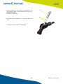
Inogun A
FCC, Standard and Robotic Versions

2Member of Exel group
DRT7133
D - 2023/01
All communication or reproduction of this document, in any form whatsoever and all use or communication of its
contents are forbidden without express written authorisation from Sames.
The descriptions and characteristics mentioned in this document are subject to change without prior notice
© Sames 2020 - translation of the original version
Sames operating manuals are written in French and translated into English, German, Spanish, Italian and Portuguese.
The French version is deemed the official text and Sames will not be liable for the translations into other languages.

3Member of Exel group
DRT7133
D - 2023/01
Services
Certification and referencing
Sames is certified as a training center by the DIRRECTE of the Auvergne Rhône Alpes region under the number 84
38 06768 38.
Our company provides, throughout the year, training courses allowing you to acquire the essential know-how for the
implementation and maintenance of your equipment in order to guarantee its performance in the long term.
A catalog is available on request.
www.sames.com/france/fr/services-training.html
Line audits
As part of a technical assistance program for our customers using Sames equipment, the line audits are intended to
help you optimize and control your production tool.
Our network of experts is continuously trained and qualified to provide our customers with technical expertise on the
liquid or powder installations in which our equipment is integrated. The global environment of the production lines is
taken into account during this technical audit.
A brochure is available for download:
www.sames.com/france/fr/services-service-contract.html
Maintenance program
An annual maintenance program (including or not the consumables to be replaced during each intervention) can be
considered with the partnership of Sames. It is associated with a preventive maintenance plan established during a
first audit visit which details the control points necessary to guarantee the performance of the installed equipment.
www.sames.com/france/fr/services-service-contract.html
Hotline
www.sames.com/france/fr/services-service-contract.html

4Member of Exel group
Inogun A
FCC, Standard and Robotic Versions
1. Health and Safety Instructions - - - - - - - - - - - - - - - - - - - - - - - - - - - - - - - - - - - - 6
1.1. Configuration of the certified equipment . . . . . . . . . . . . . . . . . . . . . . . . . . . . . . . . . . . . . . . . .6
1.1.1. Applicable Standards. . . . . . . . . . . . . . . . . . . . . . . . . . . . . . . . . . . . . . . . . . . . . . . . . . . . . . . . . . . . . . . . 6
1.2. Marking . . . . . . . . . . . . . . . . . . . . . . . . . . . . . . . . . . . . . . . . . . . . . . . . . . . . . . . . . . . . . . . . . . . . . . . . . . 7
1.3. Meaning of pictograms . . . . . . . . . . . . . . . . . . . . . . . . . . . . . . . . . . . . . . . . . . . . . . . . . . . . . . . . . . . 9
1.4. Precautions for Use . . . . . . . . . . . . . . . . . . . . . . . . . . . . . . . . . . . . . . . . . . . . . . . . . . . . . . . . . . . . 10
1.5. Warnings . . . . . . . . . . . . . . . . . . . . . . . . . . . . . . . . . . . . . . . . . . . . . . . . . . . . . . . . . . . . . . . . . . . . . . . 10
1.6. Regulatory tests to be carried out on the equipment according to standard
EN 50177 . . . . . . . . . . . . . . . . . . . . . . . . . . . . . . . . . . . . . . . . . . . . . . . . . . . . . . . . . . . . . . . . . . . . . . . . . . . 12
1.7. Important recommendations . . . . . . . . . . . . . . . . . . . . . . . . . . . . . . . . . . . . . . . . . . . . . . . . . . . 14
1.7.1. Ventilation. . . . . . . . . . . . . . . . . . . . . . . . . . . . . . . . . . . . . . . . . . . . . . . . . . . . . . . . . . . . . . . . . . . . . . . . . 14
1.7.2. O-ring seals . . . . . . . . . . . . . . . . . . . . . . . . . . . . . . . . . . . . . . . . . . . . . . . . . . . . . . . . . . . . . . . . . . . . . . . 14
1.7.3. Safety devices . . . . . . . . . . . . . . . . . . . . . . . . . . . . . . . . . . . . . . . . . . . . . . . . . . . . . . . . . . . . . . . . . . . . 14
1.7.4. Mechanical collision . . . . . . . . . . . . . . . . . . . . . . . . . . . . . . . . . . . . . . . . . . . . . . . . . . . . . . . . . . . . . . . 14
1.7.5. Ambient temperature . . . . . . . . . . . . . . . . . . . . . . . . . . . . . . . . . . . . . . . . . . . . . . . . . . . . . . . . . . . . . 14
1.8. Guarantee . . . . . . . . . . . . . . . . . . . . . . . . . . . . . . . . . . . . . . . . . . . . . . . . . . . . . . . . . . . . . . . . . . . . . . 15
2. Introduction - - - - - - - - - - - - - - - - - - - - - - - - - - - - - - - - - - - - - - - - - - - - - - - 16
3. Characteristics - - - - - - - - - - - - - - - - - - - - - - - - - - - - - - - - - - - - - - - - - - - - - 18
3.1. Dimensions (mm), straight version . . . . . . . . . . . . . . . . . . . . . . . . . . . . . . . . . . . . . . . . . . . . . 18
3.2. Dimensions (mm), gravity center for robotic versions . . . . . . . . . . . . . . . . . . . . . . . . . . 19
3.2.1. Robotic Single 60° Inogun A . . . . . . . . . . . . . . . . . . . . . . . . . . . . . . . . . . . . . . . . . . . . . . . . . . . . . . . 19
3.2.2. Robotic Twin Convergent 60° Inogun A. . . . . . . . . . . . . . . . . . . . . . . . . . . . . . . . . . . . . . . . . . . . 20
3.2.3. Robotic Twin Parallel 60° Inogun A . . . . . . . . . . . . . . . . . . . . . . . . . . . . . . . . . . . . . . . . . . . . . . . . 21
3.3. Dimensions (mm), optional extended nozzles . . . . . . . . . . . . . . . . . . . . . . . . . . . . . . . . . . 22
3.4. Dimensions (mm), 60° and 90° nozzle adapters option . . . . . . . . . . . . . . . . . . . . . . . . . 22
3.5. General characteristics . . . . . . . . . . . . . . . . . . . . . . . . . . . . . . . . . . . . . . . . . . . . . . . . . . . . . . . . . 23
3.6. Air compressed quality . . . . . . . . . . . . . . . . . . . . . . . . . . . . . . . . . . . . . . . . . . . . . . . . . . . . . . . . . 23
3.7. Operation . . . . . . . . . . . . . . . . . . . . . . . . . . . . . . . . . . . . . . . . . . . . . . . . . . . . . . . . . . . . . . . . . . . . . . 23
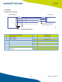
4. Diagrams - - - - - - - - - - - - - - - - - - - - - - - - - - - - - - - - - - - - - - - - - - - - - - - - - 24
4.1. Electrical connections . . . . . . . . . . . . . . . . . . . . . . . . . . . . . . . . . . . . . . . . . . . . . . . . . . . . . . . . . . 24
5. Startup - - - - - - - - - - - - - - - - - - - - - - - - - - - - - - - - - - - - - - - - - - - - - - - - - - 25
5.1. Tools . . . . . . . . . . . . . . . . . . . . . . . . . . . . . . . . . . . . . . . . . . . . . . . . . . . . . . . . . . . . . . . . . . . . . . . . . . . 25
5.2. Installation . . . . . . . . . . . . . . . . . . . . . . . . . . . . . . . . . . . . . . . . . . . . . . . . . . . . . . . . . . . . . . . . . . . . . 26
5.2.1. Inogun A FCC FCC version . . . . . . . . . . . . . . . . . . . . . . . . . . . . . . . . . . . . . . . . . . . . . . . . . . . . . . . . 26
5.2.2. Standard Inogun A version . . . . . . . . . . . . . . . . . . . . . . . . . . . . . . . . . . . . . . . . . . . . . . . . . . . . . . . . 27
5.2.3. Installation of the counter electrode for the standard Inogun A version. . . . . . . . . . . 28
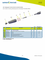
5.2.4. Installation of an extended nozzle (optional). . . . . . . . . . . . . . . . . . . . . . . . . . . . . . . . . . . . . . 29
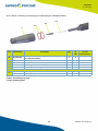
5.2.5. Installation of a 60° or 90° nozzle adapter . . . . . . . . . . . . . . . . . . . . . . . . . . . . . . . . . . . . . . . . 30
5.2.6. Robotic versions. . . . . . . . . . . . . . . . . . . . . . . . . . . . . . . . . . . . . . . . . . . . . . . . . . . . . . . . . . . . . . . . . . . 31
6. Maintenance - - - - - - - - - - - - - - - - - - - - - - - - - - - - - - - - - - - - - - - - - - - - - - 32
6.1. Summary table of maintenance operations . . . . . . . . . . . . . . . . . . . . . . . . . . . . . . . . . . . . 32
6.2. Preventive maintenance plan - PMP 7133 . . . . . . . . . . . . . . . . . . . . . . . . . . . . . . . . . . . . . 33

5Member of Exel group
6.3. Cleaning . . . . . . . . . . . . . . . . . . . . . . . . . . . . . . . . . . . . . . . . . . . . . . . . . . . . . . . . . . . . . . . . . . . . . . . 33
6.3.1. Procedure A1: Projector cleaning . . . . . . . . . . . . . . . . . . . . . . . . . . . . . . . . . . . . . . . . . . . . . . . . . . 33
6.3.2. Procedure A2: Electrode support. . . . . . . . . . . . . . . . . . . . . . . . . . . . . . . . . . . . . . . . . . . . . . . . . . 34
6.4. Replacement . . . . . . . . . . . . . . . . . . . . . . . . . . . . . . . . . . . . . . . . . . . . . . . . . . . . . . . . . . . . . . . . . . . 35
6.4.1. Procedure B1: Replacement of air nipple . . . . . . . . . . . . . . . . . . . . . . . . . . . . . . . . . . . . . . . . . . 35
6.4.2. Procedure B2: Holding flange. . . . . . . . . . . . . . . . . . . . . . . . . . . . . . . . . . . . . . . . . . . . . . . . . . . . . . 35
6.4.3. Procedure C1: Rear body . . . . . . . . . . . . . . . . . . . . . . . . . . . . . . . . . . . . . . . . . . . . . . . . . . . . . . . . . . 36
6.4.4. Procedure D1: Powder tube and penetrant testing version powder tube . . . . . . . . . 37
6.4.5. Procedure D2: Protective cover assembly. . . . . . . . . . . . . . . . . . . . . . . . . . . . . . . . . . . . . . . . . 38
6.4.6. Procedure D3: Replacement of HVU. . . . . . . . . . . . . . . . . . . . . . . . . . . . . . . . . . . . . . . . . . . . . . . 39
6.4.7. Procedure E1: Replacement of o-rings and 60° and 90° elbows. . . . . . . . . . . . . . . . . . . 40
7. Troubleshootings- - - - - - - - - - - - - - - - - - - - - - - - - - - - - - - - - - - - - - - - - - - - 42
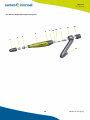
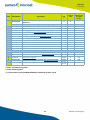
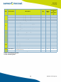
8. Spare parts list - - - - - - - - - - - - - - - - - - - - - - - - - - - - - - - - - - - - - - - - - - - - - 43
8.1. Inogun A FCC . . . . . . . . . . . . . . . . . . . . . . . . . . . . . . . . . . . . . . . . . . . . . . . . . . . . . . . . . . . . . . . . . . . 44
8.1.1. Support tube assembly for Inogun FCC . . . . . . . . . . . . . . . . . . . . . . . . . . . . . . . . . . . . . . . . . . . 45
8.2. Inogun A standard version . . . . . . . . . . . . . . . . . . . . . . . . . . . . . . . . . . . . . . . . . . . . . . . . . . . . . 46
8.3. Robotic Single 60° Inogun A projector . . . . . . . . . . . . . . . . . . . . . . . . . . . . . . . . . . . . . . . . . . 48
8.4. Robotic Twin Convergent Inogun A projector . . . . . . . . . . . . . . . . . . . . . . . . . . . . . . . . . . . 50
8.5. Robotic Twin Parallel Inogun A projector . . . . . . . . . . . . . . . . . . . . . . . . . . . . . . . . . . . . . . . 52
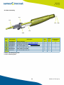
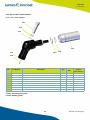
8.6. Barrel assembly . . . . . . . . . . . . . . . . . . . . . . . . . . . . . . . . . . . . . . . . . . . . . . . . . . . . . . . . . . . . . . . . 54
8.6.1. Powder tube assembly . . . . . . . . . . . . . . . . . . . . . . . . . . . . . . . . . . . . . . . . . . . . . . . . . . . . . . . . . . . . 55
8.6.2. Protective cover assembly . . . . . . . . . . . . . . . . . . . . . . . . . . . . . . . . . . . . . . . . . . . . . . . . . . . . . . . . 56
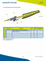
8.7. Barrel assembly, penetrant testing version . . . . . . . . . . . . . . . . . . . . . . . . . . . . . . . . . . . . 57
8.7.1. Powder tube set, penetrant testing version. . . . . . . . . . . . . . . . . . . . . . . . . . . . . . . . . . . . . . . 58
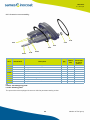
8.8. Holding flange assembly . . . . . . . . . . . . . . . . . . . . . . . . . . . . . . . . . . . . . . . . . . . . . . . . . . . . . . . 59
8.9. Equipped counter electrode . . . . . . . . . . . . . . . . . . . . . . . . . . . . . . . . . . . . . . . . . . . . . . . . . . . . 60
8.10. Electrode supports . . . . . . . . . . . . . . . . . . . . . . . . . . . . . . . . . . . . . . . . . . . . . . . . . . . . . . . . . . . 61
8.10.1. Flat spray . . . . . . . . . . . . . . . . . . . . . . . . . . . . . . . . . . . . . . . . . . . . . . . . . . . . . . . . . . . . . . . . . . . . . . . . 61
8.10.2. Optional: Extended flat spray nozzle . . . . . . . . . . . . . . . . . . . . . . . . . . . . . . . . . . . . . . . . . . . . 62
8.10.3. Round spray . . . . . . . . . . . . . . . . . . . . . . . . . . . . . . . . . . . . . . . . . . . . . . . . . . . . . . . . . . . . . . . . . . . . . 66
8.10.4. Option, Extended round spray nozzles. . . . . . . . . . . . . . . . . . . . . . . . . . . . . . . . . . . . . . . . . . . 67
8.11. Spray type conversion kits for extended nozzles . . . . . . . . . . . . . . . . . . . . . . . . . . . . . 71
8.11.1. Kit for converting a flat spray into a round spray for extended nozzles . . . . . . . . . . 71
8.11.2. Kit for converting a round spray into a flat spray for extended nozzles . . . . . . . . . . 72
8.12. 60° and 90° nozzle adapters . . . . . . . . . . . . . . . . . . . . . . . . . . . . . . . . . . . . . . . . . . . . . . . . . . 73
8.12.1. 60° nozzle adapter. . . . . . . . . . . . . . . . . . . . . . . . . . . . . . . . . . . . . . . . . . . . . . . . . . . . . . . . . . . . . . . 73
8.12.2. 90° nozzle adapter. . . . . . . . . . . . . . . . . . . . . . . . . . . . . . . . . . . . . . . . . . . . . . . . . . . . . . . . . . . . . . . 74
8.13. Additional equipment . . . . . . . . . . . . . . . . . . . . . . . . . . . . . . . . . . . . . . . . . . . . . . . . . . . . . . . . . 75
8.13.1. Fixing nut used with Inogun A FCC. . . . . . . . . . . . . . . . . . . . . . . . . . . . . . . . . . . . . . . . . . . . . . . 75
8.13.2. Fixing nut used with Inogun A. . . . . . . . . . . . . . . . . . . . . . . . . . . . . . . . . . . . . . . . . . . . . . . . . . . . 75
8.13.3. Common parts . . . . . . . . . . . . . . . . . . . . . . . . . . . . . . . . . . . . . . . . . . . . . . . . . . . . . . . . . . . . . . . . . . . 76
8.14. Robotic adapters . . . . . . . . . . . . . . . . . . . . . . . . . . . . . . . . . . . . . . . . . . . . . . . . . . . . . . . . . . . . . 76
9. Revision index History - - - - - - - - - - - - - - - - - - - - - - - - - - - - - - - - - - - - - - - - 77
10. Appendices - - - - - - - - - - - - - - - - - - - - - - - - - - - - - - - - - - - - - - - - - - - - - - 78
10.1. Preventive maintenance plan . . . . . . . . . . . . . . . . . . . . . . . . . . . . . . . . . . . . . . . . . . . . . . . . . 78
10.2. EU and UK declarations of conformity . . . . . . . . . . . . . . . . . . . . . . . . . . . . . . . . . . . . . . . . . 79

6Member of Exel group
DRT7133
D - 2023/01
1. Health and Safety Instructions
This manual contains links to the following user manuals:
•see DRT7145 for the Inobox control module.
•see DRT7134 for the Inocontroller control module.
1.1. Configuration of the certified equipment
The whole of these user manuals defines the configuration of the certified equipment.
1.1.1. Applicable Standards
The Inogun A projector has been designed according to standards indicated below:
Canadian Standards:
• CSA C22.2 No. 61010-1:12
• CSA C22.2 No. 213:19
• CSA C22.2 No. 0:20
• CSA C22.2 No. 60079-31:15 as a guide
• EN 50177:09 / A1:13 as a guide
• EN 50500-2:18 as a guide
US Standards:
• FANSI/ISA-61010-1: 3rd Ed.
• FM3600: 2018
• FM3611: 2018
• FM 7260: 2018 as a guide
• UL60079-31:2nd Ed. as a guide
Installation:
•In Canada, the installation has to be in compliance with the ″Code C22.1 Canadian Electrical part I, standard
safety for electrical installations″.
•In the USA, the installation has to be in compliance with ″NFPA 70: National Electrical Code″.

7
DRT7133
D - 2023/01
Member of Exel group
1.2. Marking
The Inogun A projector is classified as "A-P" according to EN50177.
Projectors marking:
The X sign placed after the EU/UK type examination certificate number indicates that this device is subject to special
operating conditions:
• This equipment is intended for an ambient temperature range of 0°C to 40°C.
• During the installation, the user will take into consideration that the keypad underwent only a shock
corresponding to an energy of a low risk. (see DRT7145)
•The Inobox control module has to be protected from light.
Warning markings:
"For Electrostatic Finishing Applications using Class II, spray material when configured according to 800004734", this
statement may be abbreviated to read : ‘For Electro. Fin. Appl. CL. II, Spray Matl. when configured according to
800004734’.

8Member of Exel group
DRT7133
D - 2023/01
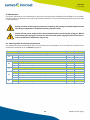
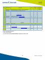
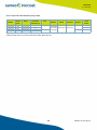
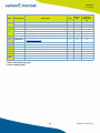
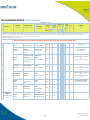
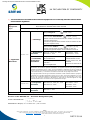
* ATEX / UKCA Inogun A configurations
Robotic versions:
Inogun A projector - P/N 910028713
Equipped barrel - P/N 910028708
Equipped rear body - P/N 910028710
Electrode support - P/N 910027640
Low voltage cable 20 m- P/N 900017990
Inogun A FCC projector - P/N 910028715
Equipped barrel - P/N 910028708
Equipped Rear body - P/N 910028710
Electrode support - P/N 910027640
Low voltage cable 30 m- P/N 900018168
P/N Inogun A
(*)
Inocontroller
P/N 910028596
X 910028713 X
X 910028715 X
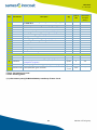
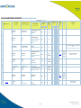
Robotic Single Inogun A projector - P/N 910030100
Equipped barrel - P/N 910028708
Equipped rear body - P/N 910028710
Electrode support - P/N 910027640
Low voltage cable 18 m- P/N 900018168
Robotic support - Réf.: 900018640
Robotic Twin Convergent Inogun A projector - P/N 910030101
Equipped barrel - P/N 910028708
Equipped Rear body - P/N 910028710
Electrode support - P/N 910027640
Low voltage cable 30 m- P/N 900018168
Robotic support - Réf.: 900018581
Robotic Twin Parallel Inogun A projector - P/N 910030102
Equipped barrel - P/N 910028708
Equipped Rear body - P/N 910028710
Electrode support - P/N 910027640
Low voltage cable 30 m- P/N 900018168
Robotic support - Réf.: 900018639
P/N Inogun A
(*)
Inocontroller
P/N 910028596
X 910030100 X
X 910030101 X
X 910030102 X

9
DRT7133
D - 2023/01
Member of Exel group
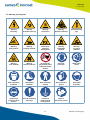
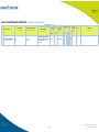
1.3. Meaning of pictograms
Warning
electricity
Warning
Automatic start-up
Warning
Hot surface
Warning
Explosive material
General warning
sign
Warning
High pressure
Warning
Crushing of hands
Warning for
explosive
atmospheres
Warning
Flammable
material
Warning
Corrosive
subtance
Warning
Toxic material
Warning
Harmful products
No access for
people with active
implanted cardiac
devices
Wear ear
protection
Wear a face
shield
Wear respiratory
protection
Wear safety
footwear
Wear protective
clothing
Wear protective
gloves
Wear head
protection
Opaque eye
protection must
be worn
General mandatory
action sign
Connect an
earth terminal
to the ground
Refer to
Instruction manual

10 Member of Exel group
DRT7133
D - 2023/01
1.4. Precautions for Use
This document contains information that all operators should be aware of and understand before using the projector.
This information highlights situations that could result in serious damage and indicates the precautions that should
be taken to avoid them.
Before any use of the Inogun A, check that all operators:
• have previously be trained by the company Sames, or by their distributors registered by them for this
purpose.
• have read and understood the user manual and all rules for installation and operation, as laid out
below.
It is the responsibility of the operators’ workshop manager to ensure these two points and it
is also his responsibility to make sure that all operators have read and understood the user
manuals for any peripheral electrical equipment present in the powdering area.
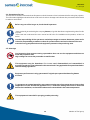
1.5. Warnings
It is imperative that anyone wearing a pacemaker does not use the equipment and does not
enter the projection area.
High voltage can cause the pacemaker to malfunction.
This equipment may be hazardous if it is not used, disassembled and reassembled in
accordance with the rules indicated in this manual and in any applicable European Standard or
national safety regulations.
Equipment performance is only guaranteed if original spare parts distributed by Sames
are used.
To guarantee an optimal assembly, spare parts must be stored in a temperature close to their
temperature of use. Should the opposite occur, a sufficient waiting time must be observed
before the installation, so that all the elements are assembled in the same temperature.
This equipment is intended for spraying powder paint only.

11
DRT7133
D - 2023/01
Member of Exel group
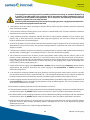
This equipment must only be used in powdering locations according to standard EN 50177 (§
5.4 and 5.7) and EN 16985. The equipment has to be used only within ventilated in order to
reduce risks for the health of the operators, fire or explosion. The efficiency of the extraction
ventilation system has to be daily checked.
Within explosive atmospheres produced by the spraying process, only appropriate explosion-
proof electrical equipment has to be used.
1 The operator must wear shoes according to standard EN ISO 20344 and the insulation resistance measured
must not exceed 100 MΩ.
2 The protective clothes, including gloves, must conform to standard EN 1149-5 and the insulation resistance
measured must not exceed 100 MΩ.
3 Using individual protection equipment will limit the risks of contact and/or inhalation of toxic product, gas,
vapours, fog or dusts that can be produced while using the equipment. The user has to follow the coating
product manufacturer’s recommendations.
4 Contact or inhalation of the products used with this equipment may be dangerous for personnel (see: safety
data sheets for the products used). The pressure coating material or compressed air must not be directed at
people or animals.
5 The parts to be painted must have a resistance to earth less than or equal to 1 MΩ (measurement voltage of
at least 500V or 1000V) (§5.7.3 in standard EN 50177). This must be checked regularly.
6 All conductive structures such as floors, powder spray station walls, ceilings, barriers, barriers, parts to be
painted, powder dispensing tank placed in or near the work area and the ground terminal of the electro-
pneumatic control module must be electrically connected to the grounding system for protecting the power
supply. Finally, and for the same reasons, it will be necessary, in the spraying area, to have an antistatic floor
such as bare concrete, metal grating, etc...
7 Switch off the power supply to the Inocontroller or Inobox before connecting the Inogun A projector. Before
disconnecting the projector, disconnect the power supply to the Inocontroller or Inobox (otherwise, a
malfunction may occur).
8 IIt is essential to properly ventilate the spray booths to avoid any powder output and to ensure a powder
concentration below the lower explosive limit (LEL). The associated equipment must be placed outside the
hazardous areas and its commissioning must be controlled by the operation of the cabin suction fan.
9 Powder spraying must be carried out in front of a ventilated station provided for this purpose. The activation of
the Inocontroller must be controlled by the operation of the ventilation system. The correct operation of the
drive must be checked once a week.
10 The ambient operating temperature must be between 0 and 40°C.
11 The electrostatic powder spraying equipment must be maintained regularly in accordance with the indications
and instructions given by Sames. Repairs must be carried out in strict accordance with these instructions.
12The electrostatic powder spraying equipment must be maintained regularly in accordance with the indications
and instructions given by Sames. Repairs must be carried out in strict accordance with these instructions.
13 Before cleaning the projectors or doing any other work in the spray area, the power supply to the high-voltage
generator must be disconnected, protected against restarting and the HV circuit protected. (projector)
discharged to ground.
Cleaning must be carried out in mechanically ventilated areas.

12 Member of Exel group
DRT7133
D - 2023/01
14 Inside the booth it is forbidden to use naked flames, glowing objects or devices likely to produce sparks.
It is also forbidden to store flammable products, or recipients that have contained them, in the vicinity of the
booth. The surrounding area must be kept clear and clean.
15In the explosive zone, it is forbidden to use non-certified electrical or non-electrical equipment such as
electrical extension cords, multi-sockets, switches, etc.
A warning sign in a language understood by the operator, summarising the safety rules described above, must be
prominently displayed in the vicinity of the powder spray station.
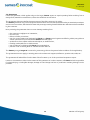
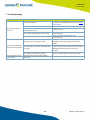
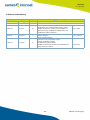
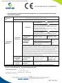
1.6. Regulatory tests to be carried out on the equipment according to standard EN 50177
The tests must be carried out on the spraying equipment. The tests must be carried out by competent personnel
and include the tests described below (see § 6.2 table 3 in standard EN 50177).
Type of test Requirements
The fixed inflammable coating powder
material electrostatic coating must be
tested to ensure it is safe for workers.
In this context, and particularly for the disconnection threshold, the overload
current Iü and the minimum voltage Umin must be defined and documented in
relation to the operational and local conditions (see also § 5.2.2 in standard
EN50177).
Forced ventilation effectiveness
(air extraction systems) See §5.4.4 in standard EN50177
The safe high voltage disconnection
must be tested for operation under
controlled voltage and under constant
voltage.
See 5.2.2 and 5.2.2.1 in standard EN50177.
The disconnection threshold Iü must be defined and documented in relation to the
operational and local conditions.
It must be tested if the high voltage is disconnected and if there is an
unacceptable increase in the operating current Ib and if the disconnection
threshold Iü is reached. In this context, the disconnection threshold Iü defined
during the initial test must be checked.
A disconnection threshold Iü that may increase the possibility of dangerous
discharges or electrical flashovers between the parts under high voltage and the
grounded parts if the safe distance falls below its permitted value is not permitted.
3D category devices See 5.2.2 and 5.2.2.1in standard EN50177
2D category devices See 5.2.2, 5.2.2.1 and 6.3 in standard EN50177

13
DRT7133
D - 2023/01
Member of Exel group
These tests must be carried out periodically The following maximum intervals between tests are recommended
(see § 7.2.3 table 4 in standard EN 50177).
For the operation at constant current,
the safe disconnection of the high
voltage electricity supply must be
tested.
See 5.2.2 and 5.2.2.2 in standard EN50177
The disconnection threshold Iü must be defined and documented in relation to the
operational and local conditions. Checks must be carried out to ensure that the
high voltage is disconnected if the high voltage falls unacceptably below the
disconnection threshold Umin. In this context, the disconnection threshold Umin
defined during the initial test must be checked.
A disconnection threshold Umin that may increase the possibility of dangerous
discharges or electrical flashovers between the parts under high voltage and the
grounded parts if the safe distance falls below its permitted value is not permitted.
3D category devices See 5.2.2 et 5.2.2.2 in standard EN50177
2D category devices See 5.2.2, 5.2.2.2 et 6.3 in standard EN50177
Protection against discharge energy
which is too high See 5.2.3 in standard EN50177
Protection against cleaning product
inflammation See 5.2.4. in standard EN50177
Effectiveness of the protection
measures against direct contact See 5.5.2 in standard EN50177
Effectiveness of the earthing
measures See 5.7 in standard EN50177
Slaving / protection against inputs See 5.5.2 in standard EN50177
Effectiveness of the local fire
extinguishing system
See 5.2.5. in standard EN50177
In addition to the location's protection system, local fire extinguishing systems
(fixed and dedicated to the object)) must provide effective protection for the
dangerous zone located between the output from the coating powder and the
part to be processed. It must be proven for each individual case that the roles of
the local fire extinguishing systems and the location's protection systems may be
satisfied by a single extinguishing system.
Other tests in accordance with standard EN 16985:2018.
Reference Test frequency
Complete installation safety test in relation to workers 12 months
Forced ventilation effectiveness in continuous
Disconnection in the event of an overload current after each start-up
Low voltage disconnection after each start-up
Discharge energy weekly
Protection against cleaning product inflammation before each cleaning
Protection against direct contact weekly
Earthing measures weekly
Protection against inputs weekly
Site's fire extinguishing system 6 months
Other tests in accordance with standard EN 16985:2018
Type of test Requirements

14 Member of Exel group
DRT7133
D - 2023/01
1.7. Important recommendations
1.7.1. Ventilation
Do not start the powder application with the Inogun A projector until the spray booth ventilation system is switched
on. If the ventilation is switched off, toxic substances or dust may remain in the spray booth and cause a risk of fire,
poisoning or irritation.
1.7.2. O-ring seals
Use the seals recommended in this manual.
1.7.3. Safety devices
When installing the projector, safety devices must be provided.
• Detection of control system faults.
• Detection of high voltage surges associated with the Sames HV generator.
• Detection of air pressure drops.
• Detection of ventilation failure.
• Detection of variations in ventilation flow rates.
• Detection of fire.
Failure to install safety devices could result in a risk of fire, expose the personnel to serious injury and
damage the equipment.
The electrostatic projection systems must be equipped with an automatic fire extinguishing
system (according to § 5.2.5 in standard EN 50177).
1.7.4. Mechanical collision
The guarantee does not cover damage resulting from the operating environment (for example: collision with the
robot).
1.7.5. Ambient temperature
The atomizer is designed to normally operate at an ambient temperature comprised between 0°C and + 40°C.
The storage temperature must never exceed +60°C.

15
DRT7133
D - 2023/01
Member of Exel group
1.8. Guarantee
Under the guarantee, which applies only to the buyer, Sames agrees to repair operating faults resulting from a
design fault, materials or manufacture, under the conditions set out below.
The guarantee claim must define the exact nature of the fault concerned, in writing.
The Sames guarantee only covers equipment that has been serviced and cleaned according to standard procedures
and our own instructions, that has been fitted with parts approved by SAMES KREMLIN or that has not been modified
by the customer.
More precisely, the guarantee does not cover damage resulting from:
• the customer's negligence or inattention,
• incorrect use,
• failure to follow procedures,
• use of a control system not designed by Sames or a Sames control system modified by a third party without
written permission from an authorized Sames technical agent,
• accidents such as: collision with external objects, or similar events,
• flooding, earthquake, fire or similar events,
• use of seals not complying with Sames recommendations,
• pollution of air circuits by fluids or substances other than air.
The Sames gun type Inogun A is covered by a warranty (refer to the general sales conditions for its application).
The guarantee does not apply to wearing parts such as electrode supports, deflectors, powder tube, seals, etc...
The guarantee will take effect from the date of the first start-up or of the provisional acceptance report.
Under no circumstances, either in the context of this guarantee or in other contexts, will Sames be held responsible
for physical injury or intangible damage, damage to brand image and loss of production resulting directly from its
products.

16 Member of Exel group
DRT7133
D - 2023/01
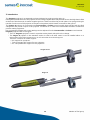
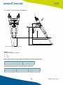
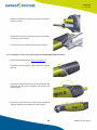
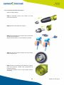
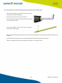
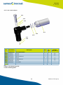
2. Introduction
The Inogun A projector is an automatic projector designed to project powder paint. An
ionizing electrode at the end of the projector is set to a high negative electrical potential. Due to the high electric field
at the end of this electrode, it creates negative gas ions. These ions allow the powder paint to be sprayed during its
transfer from the end of the projector to the part to be painted, which is itself connected to the ground.
The Inogun A projector is connected to an Inocontroller or Inobox control module that controls both the high
voltage and the powder output of the projector connected to it. These two indissociable elements constitute a
powder coating equipment.
Pre-programmed voltage and current settings can be adjusted from the Inocontroller or Inobox control module.
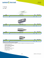
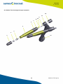
Inogun A projectors are of two types:
• The FCC Inogun A projector is used in a powder coating booth with quick colour change.
•The Inogun A projector in the standard version is used in all other cases. It can be installed either on a
reciprocator robot via its support arm or on a 6-axis robot via a robotic support.
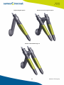
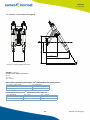
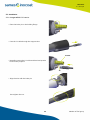
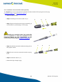
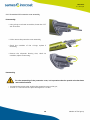
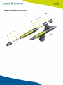
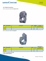
There are 3 versions of robotic support:
• 60° support for a projector.
• Twin convergent 60° support for two projectors
• 60° Twin parallel 60° support for two projectors.
Inogun A FCC
Inogun A

17
DRT7133
D - 2023/01
Member of Exel group
Robotic Twin Convergent Inogun ARobotic Single Inogun A
Robotic Twin Parallel Inogun A

18 Member of Exel group
DRT7133
D - 2023/01
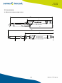
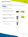
3. Characteristics
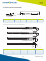
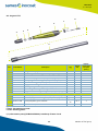
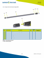
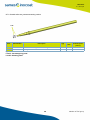
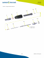
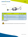
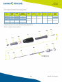
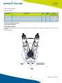
3.1. Dimensions (mm), straight version
1046
410
361
Ø30
DES07279
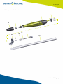
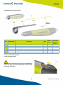
DES07280
1423
467
Ø40
Ø50

19
DRT7133
D - 2023/01
Member of Exel group
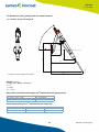
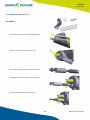
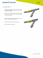
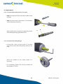
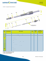
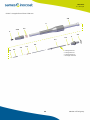
3.2. Dimensions (mm), gravity center for robotic versions
3.2.1. Robotic Single 60° Inogun A
Weight: 1.19 kg
Gravity center (GC) in millimeters:
X = 0
Y = 89.9
Z = - 136.2
Main inertia axis and moments (kg x mm2) measured to the gravity center:
Inertia moments (kg x mm2), measured to the output C.S:
Ix = (0.00, - 0.75, -0.67) Px = 6123.60
Iy = (0.00, - 0.67, - 0.75) Py = 11078.18
Iz = (1.00, 0.00, 0.00) Pz = 16650.18
Ixx = 39039.37 Ixy = -8.31 Ixz = - 49.82
Iyx = 8.31 Iyy = 25686.81 Iyz = - 6875.53
Izx = - 49.82 Izy = - 6875.53 Izz = 13904.36
DES07480
200
429,4
321,8
329,4
148,6
136,2
89,9
60°
X
Y
Z
GC
:Output C.S: Wrist Payload CG location

20 Member of Exel group
DRT7133
D - 2023/01
3.2.2. Robotic Twin Convergent 60° Inogun A
Weight : 2.2 kg
Gravity center (GC) in millimeters:
X = 0
Y = - 90
Z = - 160.4
Main inertia axis and moments (kg x mm2) measured to the gravity center:
Inertia moments (kg x mm2), measured to the output C.S:
Ix = (-0.01, - 0.88, 0.48) Px = 14739.80
Iy = (-0.03, 0.48, 0.88) Py = 29969.01
Iz = (-1.00, -0.01, - 0.03) Pz = 30163.49
Ixx = 89717,61 Ixy = 96.04 Ixz = -92.70
Iyx = 96.04 Iyy = 63587.90 Iyz = 18975.02
Izx = -92.70 Izy = 18975.02 Izz = 40677.
198
200
DES07481
323
421,4
328,5
148,2
160,4
90
vue F1
vue F1
16,4°
198
X
Y
Z
GC
Output C.S: Wrist Payload CG location
Pagina se încarcă...
Pagina se încarcă...
Pagina se încarcă...
Pagina se încarcă...
Pagina se încarcă...
Pagina se încarcă...
Pagina se încarcă...
Pagina se încarcă...
Pagina se încarcă...
Pagina se încarcă...
Pagina se încarcă...
Pagina se încarcă...
Pagina se încarcă...
Pagina se încarcă...
Pagina se încarcă...
Pagina se încarcă...
Pagina se încarcă...
Pagina se încarcă...
Pagina se încarcă...
Pagina se încarcă...
Pagina se încarcă...
Pagina se încarcă...
Pagina se încarcă...
Pagina se încarcă...
Pagina se încarcă...
Pagina se încarcă...
Pagina se încarcă...
Pagina se încarcă...
Pagina se încarcă...
Pagina se încarcă...
Pagina se încarcă...
Pagina se încarcă...
Pagina se încarcă...
Pagina se încarcă...
Pagina se încarcă...
Pagina se încarcă...
Pagina se încarcă...
Pagina se încarcă...
Pagina se încarcă...
Pagina se încarcă...
Pagina se încarcă...
Pagina se încarcă...
Pagina se încarcă...
Pagina se încarcă...
Pagina se încarcă...
Pagina se încarcă...
Pagina se încarcă...
Pagina se încarcă...
Pagina se încarcă...
Pagina se încarcă...
Pagina se încarcă...
Pagina se încarcă...
Pagina se încarcă...
Pagina se încarcă...
Pagina se încarcă...
Pagina se încarcă...
Pagina se încarcă...
Pagina se încarcă...
Pagina se încarcă...
Pagina se încarcă...
Pagina se încarcă...
Pagina se încarcă...
Pagina se încarcă...
Pagina se încarcă...
Pagina se încarcă...
Pagina se încarcă...
Pagina se încarcă...
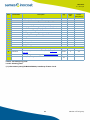
-
 1
1
-
 2
2
-
 3
3
-
 4
4
-
 5
5
-
 6
6
-
 7
7
-
 8
8
-
 9
9
-
 10
10
-
 11
11
-
 12
12
-
 13
13
-
 14
14
-
 15
15
-
 16
16
-
 17
17
-
 18
18
-
 19
19
-
 20
20
-
 21
21
-
 22
22
-
 23
23
-
 24
24
-
 25
25
-
 26
26
-
 27
27
-
 28
28
-
 29
29
-
 30
30
-
 31
31
-
 32
32
-
 33
33
-
 34
34
-
 35
35
-
 36
36
-
 37
37
-
 38
38
-
 39
39
-
 40
40
-
 41
41
-
 42
42
-
 43
43
-
 44
44
-
 45
45
-
 46
46
-
 47
47
-
 48
48
-
 49
49
-
 50
50
-
 51
51
-
 52
52
-
 53
53
-
 54
54
-
 55
55
-
 56
56
-
 57
57
-
 58
58
-
 59
59
-
 60
60
-
 61
61
-
 62
62
-
 63
63
-
 64
64
-
 65
65
-
 66
66
-
 67
67
-
 68
68
-
 69
69
-
 70
70
-
 71
71
-
 72
72
-
 73
73
-
 74
74
-
 75
75
-
 76
76
-
 77
77
-
 78
78
-
 79
79
-
 80
80
-
 81
81
-
 82
82
-
 83
83
-
 84
84
-
 85
85
-
 86
86
-
 87
87


Sames Inogun A projector Manual de utilizare
- Tip
- Manual de utilizare
în alte limbi
- English: Sames Inogun A projector User manual
Lucrări înrudite
-
Sames Inogun M Manual de utilizare
-
-
-
-
-
-
-
-
-
Alte documente
-
Tryton THL2000C Manual de utilizare
-
Vinten Quattro SE Pedestal Operator Guide
-
BenQ GS1 Manual de utilizare
-
BenQ i500 Manual de utilizare
-
Tesla RoboStar iQ300 Manual de utilizare
-
Tesla RoboStar IQ600 Manual de utilizare
-
Rittal SK 3303.470 Assembly And Operating Instructions Manual
-
Yamaha PSR-SX700 Manualul proprietarului
-
Eaton CEAG ZB-S Mounting And Operating Instructions
-
 Rovus NANO ROBOTIC VAC Instrucțiuni de utilizare
