Sames Inocart VT, Inocart H Manual de utilizare
- Categorie
- Pulverizator de vopsea
- Tip
- Manual de utilizare

Instruction manual
DRT7159
B - 2023/03
Inocart VT - Inocart H
Cart for powder gun

2
Member of Exel group DRT7159
B - 2023/03
All communication or reproduction of this document, in any form whatsoever and all use or communication of its
contents are forbidden without express written authorisation from Sames.
The descriptions and characteristics mentioned in this document are subject to change without prior notice
© Sames 2020 - Translation of the original instruction manual

3
Member of Exel group DRT7159
B - 2023/03
Services
Certification and referencing
Sames is certified as a training center by the DIRRECTE of the Auvergne Rhône Alpes region under the number 84
38 06768 38.
Our company provides, throughout the year, training courses allowing you to acquire the essential know-how for the
implementation and maintenance of your equipment in order to guarantee its performance in the long term.
A catalog is available on request.
www.sames.com/france/fr/services-training.html
Line audits
As part of a technical assistance program for our customers using Sames equipment, the line audits are intended to
help you optimize and control your production tool.
Our network of experts is continuously trained and qualified to provide our customers with technical expertise on the
liquid or powder installations in which our equipment is integrated. The global environment of the production lines is
taken into account during this technical audit.
A brochure is available for download:
www.sames.com/france/fr/services-service-contract.html
Maintenance program
An annual maintenance program (including or not the consumables to be replaced during each intervention) can be
considered with the partnership of Sames. It is associated with a preventive maintenance plan established during a
first audit visit which details the control points necessary to guarantee the performance of the installed equipment.
www.sames.com/france/fr/services-service-contract.html
Hotline
www.sames.com/france/fr/services-service-contract.html

4
Member of Exel group
Inocart VT - Inocart H
1. Health and safety instructions - - - - - - - - - - - - - - - - - - - - - - - - - - - - - - - - - - - - 6
1.1. Configuration of the certified equipment . . . . . . . . . . . . . . . . . . . . . . . . . . . . . . . . . . . . . . . . .6
1.2. Marking . . . . . . . . . . . . . . . . . . . . . . . . . . . . . . . . . . . . . . . . . . . . . . . . . . . . . . . . . . . . . . . . . . . . . . . . . . 6
1.3. Meaning of pictograms . . . . . . . . . . . . . . . . . . . . . . . . . . . . . . . . . . . . . . . . . . . . . . . . . . . . . . . . . . . 8
1.4. Simplified analysis of potential ignition sources according to EN 80079-36 . . . . . 9
1.5. Precautions for Use . . . . . . . . . . . . . . . . . . . . . . . . . . . . . . . . . . . . . . . . . . . . . . . . . . . . . . . . . . . . . .9
1.6. Warnings . . . . . . . . . . . . . . . . . . . . . . . . . . . . . . . . . . . . . . . . . . . . . . . . . . . . . . . . . . . . . . . . . . . . . . . . .9
1.7. Important recommendations . . . . . . . . . . . . . . . . . . . . . . . . . . . . . . . . . . . . . . . . . . . . . . . . . . . 12
1.7.1. Ventilation. . . . . . . . . . . . . . . . . . . . . . . . . . . . . . . . . . . . . . . . . . . . . . . . . . . . . . . . . . . . . . . . . . . . . . . . . 12
1.7.2. Valve protection for Inobox or Inocontroller control modules . . . . . . . . . . . . . . . . . . . . . 12
1.7.3. O-ring seals . . . . . . . . . . . . . . . . . . . . . . . . . . . . . . . . . . . . . . . . . . . . . . . . . . . . . . . . . . . . . . . . . . . . . . . 12
1.7.4. Ambient temperature . . . . . . . . . . . . . . . . . . . . . . . . . . . . . . . . . . . . . . . . . . . . . . . . . . . . . . . . . . . . . 12
1.7.5. Sound level. . . . . . . . . . . . . . . . . . . . . . . . . . . . . . . . . . . . . . . . . . . . . . . . . . . . . . . . . . . . . . . . . . . . . . . . 12
1.8. Guarantee . . . . . . . . . . . . . . . . . . . . . . . . . . . . . . . . . . . . . . . . . . . . . . . . . . . . . . . . . . . . . . . . . . . . . . 13
2. Introduction - - - - - - - - - - - - - - - - - - - - - - - - - - - - - - - - - - - - - - - - - - - - - - - 14
2.1. General overview . . . . . . . . . . . . . . . . . . . . . . . . . . . . . . . . . . . . . . . . . . . . . . . . . . . . . . . . . . . . . . 14
3. Characteristics - - - - - - - - - - - - - - - - - - - - - - - - - - - - - - - - - - - - - - - - - - - - - 16
3.1. General characteristics . . . . . . . . . . . . . . . . . . . . . . . . . . . . . . . . . . . . . . . . . . . . . . . . . . . . . . . . . 16
3.2. Air compressed quality . . . . . . . . . . . . . . . . . . . . . . . . . . . . . . . . . . . . . . . . . . . . . . . . . . . . . . . . . 16
4. Operation - - - - - - - - - - - - - - - - - - - - - - - - - - - - - - - - - - - - - - - - - - - - - - - - 17
4.1. With vibrating table . . . . . . . . . . . . . . . . . . . . . . . . . . . . . . . . . . . . . . . . . . . . . . . . . . . . . . . . . . . . 17
4.2. With fluidized tank . . . . . . . . . . . . . . . . . . . . . . . . . . . . . . . . . . . . . . . . . . . . . . . . . . . . . . . . . . . . . 17
5. Specific tool - - - - - - - - - - - - - - - - - - - - - - - - - - - - - - - - - - - - - - - - - - - - - - - 17
6. Installation- - - - - - - - - - - - - - - - - - - - - - - - - - - - - - - - - - - - - - - - - - - - - - - - 18
6.1. Vibrating table version . . . . . . . . . . . . . . . . . . . . . . . . . . . . . . . . . . . . . . . . . . . . . . . . . . . . . . . . . 18
6.1.1. Inocart VT dual version . . . . . . . . . . . . . . . . . . . . . . . . . . . . . . . . . . . . . . . . . . . . . . . . . . . . . . . . . . . . 19
6.2. Hopper version . . . . . . . . . . . . . . . . . . . . . . . . . . . . . . . . . . . . . . . . . . . . . . . . . . . . . . . . . . . . . . . . . 20
6.2.1. Inocart H dual version . . . . . . . . . . . . . . . . . . . . . . . . . . . . . . . . . . . . . . . . . . . . . . . . . . . . . . . . . . . . . 21
7. Use of Inocart VT or H equipment - - - - - - - - - - - - - - - - - - - - - - - - - - - - - - - - - 22
7.1. Powder application . . . . . . . . . . . . . . . . . . . . . . . . . . . . . . . . . . . . . . . . . . . . . . . . . . . . . . . . . . . . . 22
8. Maintenance - - - - - - - - - - - - - - - - - - - - - - - - - - - - - - - - - - - - - - - - - - - - - - 23
8.1. Maintenance summary table . . . . . . . . . . . . . . . . . . . . . . . . . . . . . . . . . . . . . . . . . . . . . . . . . . . 23
8.2. Preventive maintenance plan - See PMP 7159 . . . . . . . . . . . . . . . . . . . . . . . . . . . . . . . . 24
8.3. Cleaning . . . . . . . . . . . . . . . . . . . . . . . . . . . . . . . . . . . . . . . . . . . . . . . . . . . . . . . . . . . . . . . . . . . . . . . . 24
8.3.1. Procedure A: Cleaning the cart . . . . . . . . . . . . . . . . . . . . . . . . . . . . . . . . . . . . . . . . . . . . . . . . . . . . 24
8.3.2. Procedure B: Powder pump / plunger tube cleaning . . . . . . . . . . . . . . . . . . . . . . . . . . . . . . . 25
8.4. Replacement . . . . . . . . . . . . . . . . . . . . . . . . . . . . . . . . . . . . . . . . . . . . . . . . . . . . . . . . . . . . . . . . . . . 27
8.4.1. Procedure C1: Replacement of filter. . . . . . . . . . . . . . . . . . . . . . . . . . . . . . . . . . . . . . . . . . . . . . . 27
8.4.2. Procedure C2: Replacement of vibrator . . . . . . . . . . . . . . . . . . . . . . . . . . . . . . . . . . . . . . . . . . . 28
8.4.3. Procedure C3: Replacement of elastic pads of the vibrating table. . . . . . . . . . . . . . . . . 30
8.4.4. Procedure C4: Fast Clean replacement . . . . . . . . . . . . . . . . . . . . . . . . . . . . . . . . . . . . . . . . . . . . 31

5
Member of Exel group
8.4.5. Procedure C5: Replacement of the equipped porous washer. . . . . . . . . . . . . . . . . . . . . . 31
9. Spare parts list - - - - - - - - - - - - - - - - - - - - - - - - - - - - - - - - - - - - - - - - - - - - - 33
9.1. Equipment Inocart VT . . . . . . . . . . . . . . . . . . . . . . . . . . . . . . . . . . . . . . . . . . . . . . . . . . . . . . . . . . 34
9.1.1. Inocart VT cart, Europe, UK and US versions. . . . . . . . . . . . . . . . . . . . . . . . . . . . . . . . . . . . . . . 37
9.2. Equipment Inocart H . . . . . . . . . . . . . . . . . . . . . . . . . . . . . . . . . . . . . . . . . . . . . . . . . . . . . . . . . . . . 40
9.2.1. Inocart H cart, Europe and US versions . . . . . . . . . . . . . . . . . . . . . . . . . . . . . . . . . . . . . . . . . . . . 43
9.2.2. Inotank plunger tube . . . . . . . . . . . . . . . . . . . . . . . . . . . . . . . . . . . . . . . . . . . . . . . . . . . . . . . . . . . . . . 44
9.2.3. Equipped Inotank hopper . . . . . . . . . . . . . . . . . . . . . . . . . . . . . . . . . . . . . . . . . . . . . . . . . . . . . . . . . . 45
9.3. Equipment Inocart VT Dual . . . . . . . . . . . . . . . . . . . . . . . . . . . . . . . . . . . . . . . . . . . . . . . . . . . . . 46
9.3.1. Inocart VT Dual cart Europe / US . . . . . . . . . . . . . . . . . . . . . . . . . . . . . . . . . . . . . . . . . . . . . . . . . . 48
9.3.2. Inocart dual arm . . . . . . . . . . . . . . . . . . . . . . . . . . . . . . . . . . . . . . . . . . . . . . . . . . . . . . . . . . . . . . . . . . . 50
9.4. Equipment Inocart H Dual version . . . . . . . . . . . . . . . . . . . . . . . . . . . . . . . . . . . . . . . . . . . . . . 51
10. Revision index History - - - - - - - - - - - - - - - - - - - - - - - - - - - - - - - - - - - - - - - 53
11. Appendices - - - - - - - - - - - - - - - - - - - - - - - - - - - - - - - - - - - - - - - - - - - - - - 54
11.1. Maintenance preventive plan . . . . . . . . . . . . . . . . . . . . . . . . . . . . . . . . . . . . . . . . . . . . . . . . . 54
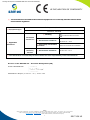
11.2. EU and UK declarations of conformity . . . . . . . . . . . . . . . . . . . . . . . . . . . . . . . . . . . . . . . . . 55

6
Member of Exel group DRT7159
B - 2023/03
1. Health and safety instructions
This manual contains links to the following operating instructions:
•see DRT6426 for the CS 130 powder pump.
•see DRT7132 for the Inogun M/M + spray gun.
•see DRT7145 for the Inobox control module.
1.1. Configuration of the certified equipment
All of these operating manuals define the configuration of the certified equipment.
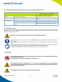
1.2. Marking
The
Inocart
is classified as category 3 according to the ATEX 2014/34/EU and SI 2016 No. 1107 directives and is
designed for use in zone 22.
The mode of protection applied is "safety by design".
DES07643
DES0
7643
DES07868
D
E
S
0
7868

7
Member of Exel group DRT7159
B - 2023/03
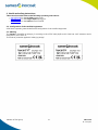
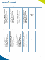
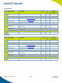
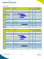
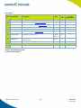
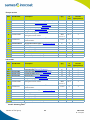
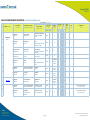
ATEX / UKCA Inocart VT configurations
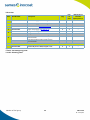
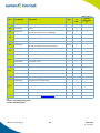
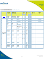
ATEX / UKCA Inocart H configurations
Inocart VT 6m Europe version - P/N 910029950
Inogun M 6m - P/N 910030034
CS 130 powder pump - P/N 910013775
Vibrator - P/N 910030011
Inocart VT 12m Europe version- P/N 910029950-12
Inogun M 12m - P/N 910030034-12
CS 130 powder pump - P/N 910013775
Vibrator - P/N 910030011
Inocart VT 6m US version - P/N 910030904
Inogun M 6m - P/N 910030034
CS 130 powder pump - P/N 910013775
Vibrator - P/N 910030896
Inocart VT 12m US version - P/N 910030904-12
Inogun M 12m - P/N 910030034-12
CS 130 powder pump - P/N 910013775
Vibrator - P/N 910030896
Inocart VT
P/N Inobox
P/N 910029983
X 910029950 X
X 910029950-12 X
X 910030904 X
X 910030904-12 X
Inocart H 6m Europe version - P/N 910030365
Inogun M 6m - P/N 910030034
Tank - P/N 910030902
Plunger tube - P/N 910030912
CS 130 powder pump - P/N 910013775
Inocart H 12m Europe version - P/N 910030365-12
Inogun M 12m - P/N 910030034-12
Tank - P/N 910030902
Plunger tube - P/N 910030912
CS 130 powder pump - P/N 910013775
Inocart H 6m US version - P/N 910030906
Inogun M 6m - P/N 910030034
Tank - P/N 910030902
Plunger tube - P/N 910030912
CS 130 powder pump - P/N 910013775
Inocart H 12m US version - P/N 910030906-12
Inogun M 12m - P/N 910030034-12
Tank - P/N 910030902
Plunger tube - P/N 910030912
CS 130 powder pump - P/N 910013775
Inocart H
P/N
Inobox
P/N 910029984
X 910030365 X
X 910030365-12 X
X 910030906 X
X 910030906-12 X

8
Member of Exel group DRT7159
B - 2023/03
1.3. Meaning of pictograms
Warning
electricity
Warning
Automatic start-up
Warning
Hot surface
Warning
Explosive material
General warning
sign
Warning
High pressure
Warning
Crushing of hands
Warning for
explosive
atmospheres
Warning
Flammable
material
Warning
Corrosive
subtance
Warning
Toxic material
Warning
Harmful products
No access for
people with active
implanted cardiac
devices
Wear ear
protection
Wear a face
shield
Wear respiratory
protection
Wear safety
footwear
Wear protective
clothing
Wear protective
gloves
Wear head
protection
Opaque eye
protection must
be worn
General mandatory
action sign
Connect an
earth terminal
to the ground
Refer to
Instruction manual

9
Member of Exel group DRT7159
B - 2023/03
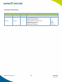
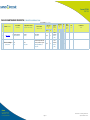
1.4. Simplified analysis of potential ignition sources according to EN 80079-36
1.5. Precautions for Use
This document contains information that all operators should be aware of and understand before using the carts
Inocart. This information highlights situations that could result in serious damage and indicates the precautions that
should be taken to avoid them.
Before any use of the Inobox control module, check that all operators:
• have previously be trained by the compagny Sames, or by their distributors registered by them for
this purpose.
• have read and understood the user manual and all rules for installation and operation, as laid out
below.
It is the responsibility of the operators’ workshop manager to ensure these two points and it is also his
responsibility to make sure that all operators have read and understood the user
manuals for any peripheral electrical equipment present in the powdering area.
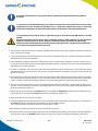
1.6. Warnings
It is imperative that anyone wearing a pacemaker does not use the equipment and does not
enter the projection area.
High voltage can cause the pacemaker to malfunction.
This equipment may be hazardous if it is not used, disassembled and reassembled in
accordance with the rules indicated in this manual and in any applicable European Standard or
national safety regulations.
This equipment is intended for spraying powder paint only.
Risk of ignition Measures applied to prevent the source of
ignition from becoming effective
Potential source of
ignition
Description / Main cause (What are the conditions
causing the risk of ignition) Description of the measure applied
Hot surface Vibrator heating in vibrating table version Maximum vibrator surface temperature of
100°C
Static electricity Internal electrostatic discharge in powder hose Antistatic hose
Electrostatic discharge on the cart Equipotentiality of the metal parts + earthing
Electrostatic discharge on the tank for the tank
version Equipotentiality of the metal parts + earthing

10
Member of Exel group DRT7159
B - 2023/03
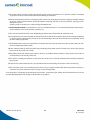
Equipment performance is only guaranteed if original spare parts distributed by Sames
are used.
To guarantee an optimal assembly, spare parts must be stored in a temperature close to their
temperature of use. Should the opposite occur, a sufficient waiting time must be observed
before the installation, so that all the elements are assembled in the same temperature.
This equipment may only be used in projection areas in accordance with EN 50050-2 and EN
16985.
Equipment should only be used in well-ventilated areas to reduce health, fire and explosion
hazards. The effectiveness of the exhaust ventilation system should be checked daily.
Within explosive atmospheres produced by the spraying process, only appropriate explosion-
proof electrical equipment has to be used.
1 The operator must wear shoes according to standard EN ISO 20344 and the insulation resistance measured
must not exceed 100 MΩ.
2 The protective clothes, including gloves, must conform to standard EN 1149-5 and the insulation resistance
measured must not exceed 100 MΩ.
3 Using individual protection equipment will limit the risks of contact and/or inhalation of toxic product, gas, va-
pours, fog or dusts that can be produced while using the equipment. The user has to follow the coating product
manufacturer’s recommendations.
4 Contact or inhalation of the products used with this equipment may be dangerous for personnel (see: safety
data sheets for the products used). The pressure coating material or compressed air must not be directed at
people or animals.
5 All conductive structures such as floors, powder spray station walls, ceilings, barriers, barriers, parts to be paint-
ed, powder dispensing tank placed in or near the work area and the ground terminal of the electro-pneumatic
control module must be electrically connected to the grounding system for protecting the power supply.
6 The floor on which the operator works must be dissipative (bare concrete floor or metal grating). Never cover
the floor with an insulating covering. In potentially explosive locations, floor assemblies must be dissipative in
accordance with EN 61340-4-1.
7 Switch off the power supply to the Inobox before connecting the Inogun M gun.Before disconnecting the gun,
cut off the power supply to the Inobox (otherwise a malfunction may occur).
8 Never point the gun at a person or animal.
9 Powder spraying must be carried out in front of a ventilated station provided for this purpose. The activation of
the Inobox must be controlled by the operation of the ventilation system.
The correct operation of the drive must be checked once a week.
10The ambient operating temperature must be between 0 and 40°C.
11The electrostatic powder spraying equipment must be maintained regularly in accordance with the indications
and instructions given by Sames. Repairs must be carried out in strict accordance with these instructions.

11
Member of Exel group DRT7159
B - 2023/03
12The electrostatic powder spraying equipment should only be operated if it is in perfect condition. Damaged
equipment must be removed from service immediately and repaired.
13Before cleaning the projectors or doing any other work in the spray area, the power supply to the high-voltage
generator must be disconnected, protected against restarting and the HV circuit protected. (spray gun) dis-
charged to ground.
Cleaning must be carried out in mechanically ventilated areas.
14In the explosive zone, it is forbidden to use non-certified electrical or non-electrical equipment such as elec-
trical extension cords, multi-sockets, switches, etc.
15The cart as well as the tanks must obligatorily be placed and used outside the explosive zone.
16It is imperative to connect the earth terminal of the cart to the earth terminal of the powder coating installation
(or of the powder coating booth) in order to ensure the safety of the operators and the correct operation of the
powder coating equipment.
17If a fluidized tank is used, it is imperative to evacuate the fumes into an area where the powder-laden air is fil-
tered (usually the powder booth).
18If the vibrating table is used, the plastic bag containing the powder must be folded down around the plunger
tube so that no powder can escape.
19Any filling of the tank with powder must be done in a ventilated area provided for this purpose and under no
circumstances in the vicinity of the cart.
20The tank is normally used placed on the lower part of the cart. It must be earthed at the terminal provided for
this purpose.
21If the tank is used outside the cart, it is imperative that it is electrically connected to earth via its body.
22The cart must under no circumstances be used to carry or transport loads other than the powder container or
a powder box with a maximum mass of 20 kg on the vibrating table.
A warning sign in a language understood by the operator, summarising the safety rules described above, must be
prominently displayed in the vicinity of the powder spray station.

12
Member of Exel group DRT7159
B - 2023/03
1.7. Important recommendations
1.7.1. Ventilation
Do not start the powder application with the Inogun M spray gun until the spray booth ventilation system is
switched on. If the ventilation is switched off, toxic substances or dust may remain in the spray booth and cause a
risk of fire, poisoning or irritation.
1.7.2. Valve protection for Inobox or Inocontroller control modules
• When using the Fast Clean on the Inocart cart, the control module must be set to cleaning mode to
prevent powder from rising in the control module valves.
• When cleaning the CS 130 powder pump with compressed air, both the injection and dilution quick
connectors must be disconnected to avoid powder backflow.
• With the Inocenter, the injection and dilution controls are activated during the cleaning process.
•When using venturi pumps without a check valve, it is important to ensure that both airs are activated
simultaneously to avoid powder backflow into the valves of the control module.
1.7.3. O-ring seals
Use the seals recommended in this manual.
1.7.4. Ambient temperature
The equipment is designed to normally operate at an ambient temperature comprised between 0°C and + 40°C
(32 °F to 104 °F)
The storage temperature must never exceed +60°C.
1.7.5. Sound level
The sound pressure level generated by Inocart VT is equal to 80.2 dBA and 78.1 dBA for the Inocart H under
the specified operating conditions.
Conditions of measurement:
The equipment was put into operation at maximum characteristics, the measurements were carried out at different
positions at 1 m from the cart without powder in the Powder laboratory at the Sames site in Meylan, France.
Method of measurement:
The accoustic pressure level, continuous, equivalent, weighted (80.2 dBA or 78.1 according to the version of the cart)
is given in LEQ value, measured for observation periods of at least 30 seconds.

13
Member of Exel group DRT7159
B - 2023/03
1.8. Guarantee
Under the guarantee, which applies only to the buyer, Sames agrees to repair operating faults resulting from a de-
sign fault, materials or manufacture, under the conditions set out below.
The guarantee claim must define the exact nature of the fault concerned, in writing.
The Sames guarantee only covers equipment that has been serviced and cleaned according to standard procedures
and our own instructions, that has been fitted with parts approved by Sames or that has not been modified by the
customer.
More precisely, the guarantee does not cover damage resulting from:
• the customer's negligence or inattention,
• incorrect use,
• failure to follow procedures,
• use of a control system not designed by Sames or a Sames control system modified by a third party without
written permission from an authorized Sames technical agent,
• accidents such as: collision with external objects, or similar events,
• flooding, earthquake, fire or similar events,
• use of seals not complying with Sames recommendations,
• pollution of air circuits by fluids or substances other than air.
The Sames carts type Inocart VT and Inocart H are covered by a warranty (refer to the general sales conditions for
its application).
The guarantee does not apply to wearing parts such as electrode supports, deflectors, powder tube, seals, etc...
The guarantee will take effect from the date of the first start-up or of the provisional acceptance report.
Under no circumstances, either in the context of this guarantee or in other contexts, will Sames be held responsible
for physical injury or intangible damage, damage to brand image and loss of production resulting directly from its
products.

14
Member of Exel group DRT7159
B - 2023/03
2. Introduction
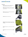
2.1. General overview
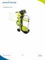
The Inocart is a space-saving and easy-to-handle cart designed for manual powder application.
The Inocart cart is equipped with the Inobox control module at the ideal height and with a inclination that can be
customized by the operator for a perfect reading of the information, as well as the Inogun M gun that is installed at
the right height on either side of the cart.
Equipped with several air quick couplers, its use and maintenance are optimized compared to previous generations.
Available in two versions:
•Inocart VT: Equipped with a vibrating table that can support a 20 kg powder box, it is designed for frequent
and quick color changes. It is also equipped with a removable support arm and an integrated cleaning system:
Fast Clean.
•Inocart H: Equipped with a fluidized tank with a capacity of 50l, it is designed for fewer color changes but for
high production and complex powders that require complete fluidization.

15
Member of Exel group DRT7159
B - 2023/03
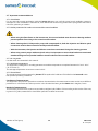
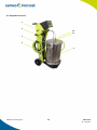
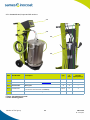
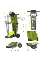
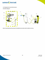
Inocart VT equipment
1 Inobox VT control module
2CS 130 powder pump
3Arm
4Plunger tube
5 Vibrating table
6 Inogun M spray gun
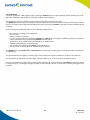
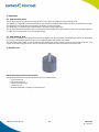
Inocart H equipment
1Inobox H control module
2 CS 130 powder pump
3Tank
4 Inogun M spray gun
1
2
4
5
3
6
2
1
3
4

16
Member of Exel group DRT7159
B - 2023/03
3. Characteristics
3.1. General characteristics
The structure of the cart makes it possible to place:
• on a vibrating table, a box with a maximum mass of 20 kg of powder in an inclined way.
• a tank that can contain about 50 useful liters of fluidized powder, i.e. 20 kg.
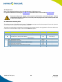
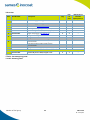
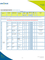
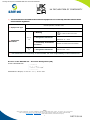
3.2. Air compressed quality
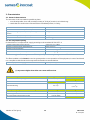
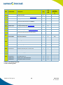
Characteristics of compressed air supply according to the standard NF ISO 8573-1:
*: Values are given for a temperature of 20 °C (68 °F) at an atmospheric pressure of 1 013 mbar
The filter installed on the Inocart is used to guarantee the correct operation of the equipment, in case of accidental
non-compliance with the network compressed air filtration recommendations.
(*) A pressure higher than 8 bar can cause malfunctions.
Dimensions of the Inocart VT (H x W x D) 1230 x 490 x 630 mm
Dimensions of the Inocart H (H x W x D) 1230 x 490 x 670 mm
Approximate weight (without powder), vibrating table
version
42 kg.
Approximate weight (without powder), tank version 37 kg.
Standard flow rate 50 to 450 g/min.
Maximum dew point at 6 bar (87 psi) Class 4 i.e + 3°C (38°F)
Maximum particle-size of solid pollutants Class 3 i.e 5 μm
Maximum oil concentration Class 1 i.e 0,01 mg / m03 *
Maximum concentration of solid pollutants Class 3 i.e 5mg / m03 *
Inocart" equipment air supply pressure 7 bar +/- 1 bar (*)
Max. air consumption of the Inobox control module Vibrating table version Tank version
Fluidization air flow rate plunger tube 0,1 m3/h
Tank fluidization air flow rate 2,1 m3/h
Electrode blowing
0,1 m3/h
0,1 m3/h
Gun + powder pump + fluidization assembly
Powder coating 6,5 m3/h 8,5 m3/h
In cleaning 9,5 m3/h 9,5 m3/h
Air consumption of Fast Clean at 7bar 7 l/s per pulse

17
Member of Exel group DRT7159
B - 2023/03
4. Operation
4.1. With vibrating table
The powder paint is contained in its original box of up to 20kg. It is placed on the vibrating table.
The vibration of the table is obtained thanks to the vibrator and allows the fluidizing head to penetrate the powder.
The operation of the vibrator is triggered by an action on the gun trigger.
The fluidizing rod, supplied with compressed air, "fluidizes" the powder paint.
The powder paint thus fluidized is then suctioned and then delivered by the powder pump to the powder projector,
to which it is connected via a powder transport hose.
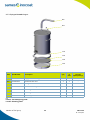
4.2. With fluidized tank
The powder contained in the tank, with a maximum capacity of 50 l of powder, is fluidized by means of an ascending
air current, evenly distributed through a porous plate located at the base of the tank.
The fluidized powder paint is then extracted and discharged by the powder pump to the powder projector. The
fumes are extracted by means of a 40 mm section hose which must be connected to the booth side.
5. Specific tool
Other necessary tools and accessories:
The tools listed below are recommended for product maintenance.
• Torx screwdriver
• Flat wrench 10 mm
• Socket wrench 10 mm
•Torque wrench
• Blue tthreadlocker (normal) P/N: H2CPAL046.

18
Member of Exel group DRT7159
B - 2023/03
6. Installation
The Inocart VT or H carts are delivered assembled.
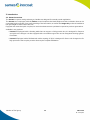
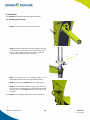
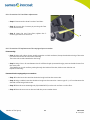
6.1. Vibrating table version
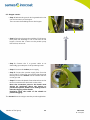
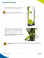
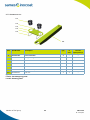
•Step 1: Place the support arm in its housing.
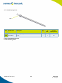
•Step 2: Place the plunger tube (A) equipped with the
CS 130 pump in the support arm and connect the 2
hoses to the powder pump blue to blue, red to red.
Connect the fluidizing hose to the tube.
•Step 3: Connect the 5 m earthing cable to an
electrically earthed part of the application booth.
•Step 4: Connect the Inobox's power supply plug.
•Step 5: Connect the powder supply hose from the
gun to the CS 130 pump and connect the electrode
blowing hose on the Inobox module side and on the
gun side.
The Inocart cart is ready to start the powder application.
A

19
Member of Exel group DRT7159
B - 2023/03
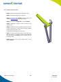
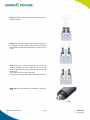
6.1.1. Inocart VT dual version
•Step 1: Place the wall bracket on the cabin wall.
•Step 2: Install the dual plunger wiring set.
•Step 3: Install the 2nd Inobox control module and
connect (see DRT7145) the 2nd wiring set.
•Step 4: Connect the Inogun M 6 m to the Inobox.
•Step 5: Install the support of the 2 tubes on the
support arm.
•Step 6: Install the 2 tubes equipped with the 2 CS130
pumps, connect the 2 tubes to the second powder
pump, blue to blue, red to red.
Connect the fluidizing hose to the tube.
•Step 7: Connect the powder hose of the 2nd gun to
the 2nd pump CS 130 and connect the electrode
blowing hose on the Inobox control module side and
on the gun side.
•Step 8: Connect the power supply cable of the
second Inobox.

20
Member of Exel group DRT7159
B - 2023/03
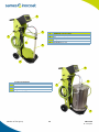
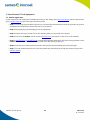
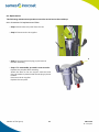
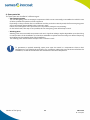
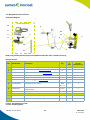
6.2. Hopper version
•Step 1: Release the ground wire lug attached to the
cart and connect it to the hopper.
Then connect the fluidizing hose to the hopper.
•Step 2: Equip the plunger tube with the CS 130 pump,
then place the assembly in one of the holes in the
hopper. Connect the 2 hoses on the powder pump
blue to blue, red to red.
•Step 3: Connect the 5 m ground cable to an
electrically grounded part of the powdering booth.
•Step 4: Connect the Inobox power supply.
•Step 5: Connect the powder supply hose from the
gun to the CS 130 pump and connect the electrode
blowing hose on the Inobox controll module side and
on the gun side.
•Step 6: Connect the plastic fume exhaust hose to the
tank on one side and to the booth on the other.
Note: the connection point on the booth must
always be positioned above the hopper to
prevent the plastic sheath from "sinking" and to
limit the clogging of the sheath.
Regularly check the inside of the sheath to
prevent clogging.
The Inocart H cart is ready to start the powder application.
Pagina se încarcă...
Pagina se încarcă...
Pagina se încarcă...
Pagina se încarcă...
Pagina se încarcă...
Pagina se încarcă...
Pagina se încarcă...
Pagina se încarcă...
Pagina se încarcă...
Pagina se încarcă...
Pagina se încarcă...
Pagina se încarcă...
Pagina se încarcă...
Pagina se încarcă...
Pagina se încarcă...
Pagina se încarcă...
Pagina se încarcă...
Pagina se încarcă...
Pagina se încarcă...
Pagina se încarcă...
Pagina se încarcă...
Pagina se încarcă...
Pagina se încarcă...
Pagina se încarcă...
Pagina se încarcă...
Pagina se încarcă...
Pagina se încarcă...
Pagina se încarcă...
Pagina se încarcă...
Pagina se încarcă...
Pagina se încarcă...
Pagina se încarcă...
Pagina se încarcă...
Pagina se încarcă...
Pagina se încarcă...
Pagina se încarcă...
Pagina se încarcă...
Pagina se încarcă...
Pagina se încarcă...
Pagina se încarcă...
Pagina se încarcă...
Pagina se încarcă...
Pagina se încarcă...
Pagina se încarcă...
Pagina se încarcă...
Pagina se încarcă...
Pagina se încarcă...
-
 1
1
-
 2
2
-
 3
3
-
 4
4
-
 5
5
-
 6
6
-
 7
7
-
 8
8
-
 9
9
-
 10
10
-
 11
11
-
 12
12
-
 13
13
-
 14
14
-
 15
15
-
 16
16
-
 17
17
-
 18
18
-
 19
19
-
 20
20
-
 21
21
-
 22
22
-
 23
23
-
 24
24
-
 25
25
-
 26
26
-
 27
27
-
 28
28
-
 29
29
-
 30
30
-
 31
31
-
 32
32
-
 33
33
-
 34
34
-
 35
35
-
 36
36
-
 37
37
-
 38
38
-
 39
39
-
 40
40
-
 41
41
-
 42
42
-
 43
43
-
 44
44
-
 45
45
-
 46
46
-
 47
47
-
 48
48
-
 49
49
-
 50
50
-
 51
51
-
 52
52
-
 53
53
-
 54
54
-
 55
55
-
 56
56
-
 57
57
-
 58
58
-
 59
59
-
 60
60
-
 61
61
-
 62
62
-
 63
63
-
 64
64
-
 65
65
-
 66
66
-
 67
67


Sames Inocart VT, Inocart H Manual de utilizare
- Categorie
- Pulverizator de vopsea
- Tip
- Manual de utilizare
în alte limbi
Lucrări înrudite
-
Sames HF Pressure Tank Manual de utilizare
-
-
-
-
-
-
-
-
-