Sames HF Pressure Tank Manual de utilizare
- Tip
- Manual de utilizare

Instruction manual
DRT7170
B - 2023/10
HF Pressure Tank

2
Member of Exel group DRT7170
B - 2023/10
All communication or reproduction of this document, in any form whatsoever and all use or communication of its
contents are forbidden without express written authorisation from Sames.
The descriptions and characteristics mentioned in this document are subject to change without prior notice
© Sames 2020 - Translation of the original instruction manual

3
Member of Exel group DRT7170
B - 2023/10
Services
Certification and referencing
Sames is certified as a training center by the DIRRECTE of the Auvergne Rhône Alpes region under the number 84
38 06768 38.
Our company provides, throughout the year, training courses allowing you to acquire the essential know-how for the
implementation and maintenance of your equipment in order to guarantee its performance in the long term.
A catalog is available on request.
www.sames.com/france/en/services-training.html
Line audits
As part of a technical assistance program for our customers using Sames equipment, the line audits are intended to
help you optimize and control your production tool.
Our network of experts is continuously trained and qualified to provide our customers with technical expertise on the
liquid or powder installations in which our equipment is integrated. The global environment of the production lines is
taken into account during this technical audit.
A brochure is available for download:
www.sames.com/france/en/services-service-contract.html
Maintenance program
An annual maintenance program (including or not the consumables to be replaced during each intervention) can be
considered with the partnership of Sames. It is associated with a preventive maintenance plan established during a
first audit visit which details the control points necessary to guarantee the performance of the installed equipment.
www.sames.com/france/en/services-service-contract.html
Hotline
www.sames.com/france/en/services-service-contract.html

4
Member of Exel group
HF Pressure Tank
1. Health and safety instructions - - - - - - - - - - - - - - - - - - - - - - - - - - - - - - - - - - - - 5
1.1. Marking . . . . . . . . . . . . . . . . . . . . . . . . . . . . . . . . . . . . . . . . . . . . . . . . . . . . . . . . . . . . . . . . . . . . . . . . . . 5
1.2. Meaning of pictograms . . . . . . . . . . . . . . . . . . . . . . . . . . . . . . . . . . . . . . . . . . . . . . . . . . . . . . . . . . . 6
1.3. Simplified analysis of potential ignition sources according to EN 80079-36 . . . . . 7
1.4. Precautions for Use . . . . . . . . . . . . . . . . . . . . . . . . . . . . . . . . . . . . . . . . . . . . . . . . . . . . . . . . . . . . . . 7
1.5. Warnings . . . . . . . . . . . . . . . . . . . . . . . . . . . . . . . . . . . . . . . . . . . . . . . . . . . . . . . . . . . . . . . . . . . . . . . . . 7
1.6. Important recommendations . . . . . . . . . . . . . . . . . . . . . . . . . . . . . . . . . . . . . . . . . . . . . . . . . . . . . 9
1.6.1. Ventilation. . . . . . . . . . . . . . . . . . . . . . . . . . . . . . . . . . . . . . . . . . . . . . . . . . . . . . . . . . . . . . . . . . . . . . . . . . . 9
1.6.2. O-ring seals . . . . . . . . . . . . . . . . . . . . . . . . . . . . . . . . . . . . . . . . . . . . . . . . . . . . . . . . . . . . . . . . . . . . . . . . . 9
1.6.3. Ambient temperature . . . . . . . . . . . . . . . . . . . . . . . . . . . . . . . . . . . . . . . . . . . . . . . . . . . . . . . . . . . . . . . 9
1.6.4. Sound level. . . . . . . . . . . . . . . . . . . . . . . . . . . . . . . . . . . . . . . . . . . . . . . . . . . . . . . . . . . . . . . . . . . . . . . . . . 9
2. Description - - - - - - - - - - - - - - - - - - - - - - - - - - - - - - - - - - - - - - - - - - - - - - - 10
3. Characteristics - - - - - - - - - - - - - - - - - - - - - - - - - - - - - - - - - - - - - - - - - - - - - 11
3.1. General characteristics . . . . . . . . . . . . . . . . . . . . . . . . . . . . . . . . . . . . . . . . . . . . . . . . . . . . . . . . . 11
3.2. Air compressed quality . . . . . . . . . . . . . . . . . . . . . . . . . . . . . . . . . . . . . . . . . . . . . . . . . . . . . . . . . 11
4. Operation - - - - - - - - - - - - - - - - - - - - - - - - - - - - - - - - - - - - - - - - - - - - - - - - 12
5. Start up- - - - - - - - - - - - - - - - - - - - - - - - - - - - - - - - - - - - - - - - - - - - - - - - - - 13
5.1. Specific tool . . . . . . . . . . . . . . . . . . . . . . . . . . . . . . . . . . . . . . . . . . . . . . . . . . . . . . . . . . . . . . . . . . . . 13
5.2. Installation for wall version . . . . . . . . . . . . . . . . . . . . . . . . . . . . . . . . . . . . . . . . . . . . . . . . . . . . . 13
5.2.1. Connections . . . . . . . . . . . . . . . . . . . . . . . . . . . . . . . . . . . . . . . . . . . . . . . . . . . . . . . . . . . . . . . . . . . . . . . 13
5.3. Use of the NF pressure tank in wall-mounted version . . . . . . . . . . . . . . . . . . . . . . . . . . 14
6. Maintenance - - - - - - - - - - - - - - - - - - - - - - - - - - - - - - - - - - - - - - - - - - - - - - 15
6.1. Maintenance summary table . . . . . . . . . . . . . . . . . . . . . . . . . . . . . . . . . . . . . . . . . . . . . . . . . . . 15
6.2. Cleaning . . . . . . . . . . . . . . . . . . . . . . . . . . . . . . . . . . . . . . . . . . . . . . . . . . . . . . . . . . . . . . . . . . . . . . . . 15
6.2.1. Procedure A: Cleaning of the equipment . . . . . . . . . . . . . . . . . . . . . . . . . . . . . . . . . . . . . . . . . . 15
6.2.2. Procedure B: Cleaning of the injection air check valve . . . . . . . . . . . . . . . . . . . . . . . . . . . . . 16
6.2.3. Procedure C: Dump of tank . . . . . . . . . . . . . . . . . . . . . . . . . . . . . . . . . . . . . . . . . . . . . . . . . . . . . . . . 16
6.3. Replacement . . . . . . . . . . . . . . . . . . . . . . . . . . . . . . . . . . . . . . . . . . . . . . . . . . . . . . . . . . . . . . . . . . . 17
6.3.1. Procedure D1: Replacement of filter. . . . . . . . . . . . . . . . . . . . . . . . . . . . . . . . . . . . . . . . . . . . . . . 17
6.3.2. Procedure D2: Replacement of vibrator . . . . . . . . . . . . . . . . . . . . . . . . . . . . . . . . . . . . . . . . . . . 18
7. Troubleshootings- - - - - - - - - - - - - - - - - - - - - - - - - - - - - - - - - - - - - - - - - - - - 19
8. Spare parts list - - - - - - - - - - - - - - - - - - - - - - - - - - - - - - - - - - - - - - - - - - - - - 20
8.1. Equipment Minigun HF, Europe and US versions . . . . . . . . . . . . . . . . . . . . . . . . . . . . . . . . 21
8.1.1. HF pressure tank Europe and US versions . . . . . . . . . . . . . . . . . . . . . . . . . . . . . . . . . . . . . . . . . 24
8.1.2. Injector assembly. . . . . . . . . . . . . . . . . . . . . . . . . . . . . . . . . . . . . . . . . . . . . . . . . . . . . . . . . . . . . . . . . . 26
9. Revision index History - - - - - - - - - - - - - - - - - - - - - - - - - - - - - - - - - - - - - - - - 27
10. Appendices - - - - - - - - - - - - - - - - - - - - - - - - - - - - - - - - - - - - - - - - - - - - - - 28
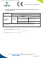
10.1. EU-and UK Declarations of conformity . . . . . . . . . . . . . . . . . . . . . . . . . . . . . . . . . . . . . . . . 28

5
Member of Exel group DRT7170
B - 2023/10
1. Health and safety instructions
This manual contains links to the following operating instructions:
•see DRT7132 for the Inogun M spray gun.
•see DRT7145 for the Inobox control module.
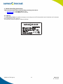
1.1. Marking
The
HF Pressure Tank
is classified as category 3 according to the ATEX 2014/34/EU and SI 2016 No. 1107 directives
and is designed for use in zone 22.
The mode of protection applied is "safety by design".
DES07879

6
Member of Exel group DRT7170
B - 2023/10
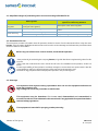
1.2. Meaning of pictograms
Warning
electricity
Warning
Automatic start-up
Warning
Hot surface
Warning
Explosive material
General warning
sign
Warning
High pressure
Warning
Crushing of hands
Warning for
explosive
atmospheres
Warning
Flammable
material
Warning
Corrosive
subtance
Warning
Toxic material
Warning
Harmful products
No access for
people with active
implanted cardiac
devices
Wear ear
protection
Wear a face
shield
Wear respiratory
protection
Wear safety
footwear
Wear protective
clothing
Wear protective
gloves
Wear head
protection
Opaque eye
protection must
be worn
General mandatory
action sign
Connect an
earth terminal
to the ground
Refer to
Instruction manual

7
Member of Exel group DRT7170
B - 2023/10
1.3. Simplified analysis of potential ignition sources according to EN 80079-36
1.4. Precautions for Use
This document contains information that all operators should be aware of and understand before using the carts
Inocart. This information highlights situations that could result in serious damage and indicates the precautions that
should be taken to avoid them.
Before any use of the Inobox control module, check that all operators:
• have previously be trained by the company Sames, or by their distributors registered by them for this
purpose.
• have read and understood the user manual and all rules for installation and operation, as laid out
below.
It is the responsibility of the operators’ workshop manager to ensure these two points and it is also his
responsibility to make sure that all operators have read and understood the user
manuals for any peripheral electrical equipment present in the powdering area.
1.5. Warnings
It is imperative that anyone wearing a pacemaker does not use the equipment and does not
enter the projection area.
High voltage can cause the pacemaker to malfunction.
This equipment may be hazardous if it is not used, disassembled and reassembled in
accordance with the rules indicated in this manual and in any applicable European Standard or
national safety regulations.
This equipment is intended for spraying powder paint only.
Risk of ignition Measures applied to prevent the source of
ignition from becoming effective
Potential source
of ignition
Description / Main cause (What are the conditions
causing the risk of ignition) Description of the measure applied
Hot surface Vibrator heating in vibrating table version Maximum vibrator surface temperature of
100°C
Static electricity Internal electrostatic discharge in powder hose Antistatic hose
Electrostatic discharge on the pressure tank Equipotentiality of the metal parts + earthing

8
Member of Exel group DRT7170
B - 2023/10
Equipment performance is only guaranteed if original spare parts distributed by Sames
are used.
To guarantee an optimal assembly, spare parts must be stored in a temperature close to their
temperature of use. Should the opposite occur, a sufficient waiting time must be observed
before the installation, so that all the elements are assembled in the same temperature.
1 It is imperative to connect the ground terminal of the tank to the ground terminal of the powder coating
installation (or powder booth) in order to ensure the safety of the operators as well as the correct operation of
the powder coating equipment.
2 Using individual protection equipment will limit the risks of contact and/or inhalation of toxic product, gas,
vapors, fog or dusts that can be produced while using the equipment.
The user has to follow the coating product manufacturer’s recommendations.
3 Contact or inhalation of the products used with this equipment may be dangerous for personnel (see: safety
data sheets for the products used). The pressure coating material or compressed air must not be directed at
people or animals.
4 Any filling of the tank with powder must be done in a ventilated area provided for this purpose.
It is imperative to switch off all power supplies during the filling or emptying phases of the tank.
5 The electrostatic powder spraying equipment must be maintained regularly in accordance with the indications
and instructions given by Sames.
Repairs must be carried out in strict accordance with these instructions.

9
Member of Exel group DRT7170
B - 2023/10
1.6. Important recommendations
1.6.1. Ventilation
Do not start the powder application with the Inogun M spray gun until the spray booth ventilation system is
switched on. If the ventilation is switched off, toxic substances or dust may remain in the spray booth and cause a
risk of fire, poisoning or irritation.
1.6.2. O-ring seals
Use the seals recommended in this manual.
1.6.3. Ambient temperature
The equipment is designed to normally operate at an ambient temperature comprised between 0°C and + 40°C
(32 °F to 104 °F)
The storage temperature must never exceed +60°C.
1.6.4. Sound level
The sound pressure level generated by the vibrator is 65.6 dBA under the specified operating conditions.
Conditions of measurement:
The equipment was put into operation at maximum characteristics, the measurements were carried out at different
positions at 1 m from the cart and 1.6 m from the ground without the presence of powder in the Powder laboratory
on the Sames site in Meylan, France.
Method of measurement:
The acoustic pressure level, continuous, equivalent, weighted (65.6 dBA) is given in LEQ value, measured for obser-
vation periods of at least 30 seconds.

10
Member of Exel group DRT7170
B - 2023/10
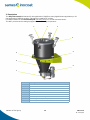
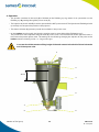
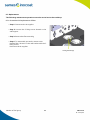
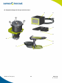
2. Description
The HF pressure tank is intended for the application of high flow rates (high thickness application) or for
the application of difficult powders. The pot has a capacity of 24 liters.
It is either installed on the Inocart NDT/HF (see DRT7161), or in a wall-mounted version.
The NDT pressure tank is mainly equipped with the following components:
Item Description
1Cover
2Quick release valve
3Lever
4Locking clamp
5Support
6Vibrator
7Injector / ejector assembly
8Tank body (contains powder paint)
9Elastic support
4
5
6
7
9
8
1 2 3

11
Member of Exel group DRT7170
B - 2023/10
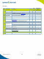
3. Characteristics
3.1. General characteristics
•HF pressure tank capacity: total volume 24 liters, i.e. about 10 to 12 kg of fluidized powder depending on its
density.
• Total weight without powder of pressure tank + support: 18 kg
• The vibrator used on the HF pressure tank is electric.
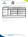
3.2. Air compressed quality
*: Values are given for a temperature of 20 °C (68 °F) at an atmospheric pressure of 1 013 mbar
Failure to comply with these characteristics may cause the Inobox control module to
malfunction.
A filter 5 μm must be installed upstream of the compressed air supply of the Inobox control
module. This filter is dimensioned according to the size of the system.
Sames recommends using a filter of the type indicated (see DRT7161). In case of damage to the
equipment due to the use of polluted air, the warranty may not be applied
(*) A pressure higher than 8 bar can cause malfunctions.
Characteristics of compressed air supply according to the standard NF ISO 8573-1:
Maximum dew point at 6 bar (87 psi) Class 4 i.e + 3°C (37°F)
Maximum particle-size of solid pollutants Class 3 i.e 5 μm
Maximum oil concentration Class 1 i.e 0,01 mg/m03 *
Maximum concentration of solid pollutants Class 3 i.e 5 mg/m03 *
Equipment supply air pressure 7 bar +/- 1 bar (*)
Total air flow rate 85 l/min

12
Member of Exel group DRT7170
B - 2023/10
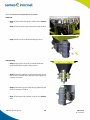
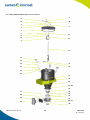
4. Operation
• The powder contained in the tank (3) is fluidized at the fluidizing cup by means of air (connection on the
fluidizing cup 6) passing through the porous cone (7).
• The injection air (check valve 5) is used to pressurize the NDT pressure tank. The injection and fluidizing air add
up and help to transport the powder to the projector.
• The electric vibrator (4) prevents powder accumulation in the porous cone.
•On the Inobox control module, the injection setpoint must be set to 80 and the fluidization to 43.
The powder flow rate is adjusted using the lever (1) on the cover. This actuates the shutter (2) which more or
less closes the powder ejector tube. The setting can be refined by changing the injection air set point on the
Inobox module or directly on the + or - keys on the gun.
In no case should the maximum filling height of the tank exceed a threshold of 10 cm below the
end of the ejector tube.
1
10 cm
2
4
6 5
7
3

13
Member of Exel group DRT7170
B - 2023/10
5. Start up
5.1. Specific tool
None
5.2. Installation for wall version
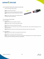
5.2.1. Connections
Item Description
1PLC connection
2Spray gun connection
3Vibration connection
4Power supply 100 / 240 VAC
5Earth connection terminal
6Not connected
7Electrode Blowing air outlet
8Fluidization air outlet
9Injection air outlet
10 Air supply
12345
67
8
910

14
Member of Exel group DRT7170
B - 2023/10
5.3. Use of the NF pressure tank in wall-mounted version
As the equipment has already been installed according to the safety rules (see § 1 page 5) follow the steps
described below:
•Step 1: Connect the ground cable of the tank to a conductive and earthed part of the spray booth; the ground
potential must be identical to that of the part to be powdered.
•Step 2: Electrically and pneumatically power the equipment.
•Step 3: Put powder in the pressure tank and close the lid with the clamps.
Tank under pressure in operation.
•Step 4: Switch on the Inobox control module (see DRT7145) (ON button on the front of the module.
Configure the Inobox NF control module (see DRT7145), for pressure tank operation. The fluidizing outlet at
the rear of the module must be plugged.
•Step 5: Choose the appropriate high-voltage feature or create a custom program.
•Step 6: Point the gun nozzle towards the booth and the part to be powdered and press the trigger.
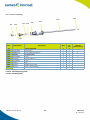
The HF pressure tank is equipped with a 1.7 m injector and a 9/13 inner diameter hose with a fitting on the cover.
Set the injection parameter on the Inobox module to 80 and the fluidization to 43.
Then adjust the powder flow rate by adjusting the position of the shutter on the tank.
As an indication, with 6 m of 9mm hose and with a standard powder
Shutter position 12345
Powder flow rate (kg/h) 6 14447080

15
Member of Exel group DRT7170
B - 2023/10
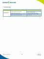
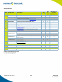
6. Maintenance
6.1. Maintenance summary table
The soiling and wear of the different elements of the HF pressure tanK caused by the passage of the powder
depends on the nature of the powder and the operating conditions.
Therefore, the periodicity of maintenance indicated in the procedures below is only indicative. The user will have to
create his own maintenance range as he uses the Sames equipment.
6.2. Cleaning
6.2.1. Procedure A: Cleaning of the equipment
Before any intervention, refer to the health and safety instructions (see § 1 page 5).
Always wear safety glasses.
When handling powder, wear gloves of a suitable resistant material
Work in a well ventilated area.
All cleaning operations should only be carried out using compressed air at a maximum pressure
of 2.5 bar, a cloth or possibly a brush. Never use water or solvents to clean the equipment.
•Clean the complete Inocart cart with compressed air every 8 hours.
Procedure Detail Duration Frequency
Cleaning
ACleaning of the equipment 2 min 8 hours
BCleaning of the injection air check valve 2 min -
CDump of tank 5 min 8 hours or at each
color change
Replacement
DD1 Replacement of filter 30 min -
F2 Replacement of vibrator 1 Hour -

16
Member of Exel group DRT7170
B - 2023/10
6.2.2. Procedure B: Cleaning of the injection air check valve
• Switch off the high-voltage supply,
•Step 1: Switch off the air supply
•Step 2: Disconnect the hose upstream of the valve by
pressing the green ring, then downstream on the red
ring.
•Step 3: Then clean the valve with compressed air. If
necessary, clean the tank injector.
6.2.3. Procedure C: Dump of tank
6.2.3.1. Procedure 1
•Step 1: Disconnect the air supplies on the tank.
•Step 2: Remove the cover by unscrewing the clamps.
•Step 3: Disconnect the ground wire from the tank.
•Step 4: Unscrew the 3 knobs that secure the tank to the tank holder. Take out the tank, taking care not to
shock the vibrator.
•Step 5: Empty the tank into the booth and clean the remaining powder with compressed air.
6.2.3.2. Procedure 2
•Step 1: Disconnect the injection air supply to the pressure tank.
•Step 2: Place a recovery box under the pressure tank.
•Step 3: Unscrew the threaded ring and pull the injector/ejector assembly upwards. The powder then falls into
the tray. Clean the remaining powder with compressed air.

17
Member of Exel group DRT7170
B - 2023/10
6.3. Replacement
The following maintenance operations are to be carried out in the workshop.
6.3.1. Procedure D1: Replacement of filter
•Step 1: Disconnect the air supplies.
•Step 2: Unscrew the 2 fixing screws located on the
wall support.
•Step 3: Remove the filter assembly.
•Step 4: To reassemble, proceed in reverse order:
Replace filter. Secure it to the wall bracket with the 2
fixing screws.
Reconnect the air supplies.
Fixing screws (2)

18
Member of Exel group DRT7170
B - 2023/10
6.3.2. Procedure D2: Replacement of vibrator
Removal
•Step 1: Disconnect the vibrator cable on the Inobox
side.
•Step 2: Disconnect the ground wire from the vibrator.
•Step 3 Unscrew the 4 vibrator fastening screws.
Reassembly
•Step 4: Apply a few drops of normal threadlocker
(P/N H2CPAL046) on the 4 fixing screws.
•Step 5: Place the vibrator on the pressure tank, screw
the screws crosswise and in approach, then tighten to
a torque of 10 N.m.
•Step 6: Attach the ground cable lug by tightening the
screw to a torque of 7 N.m.
•Step 7: Reconnect the vibrator cable on the Inobox
side.

19
Member of Exel group DRT7170
B - 2023/10
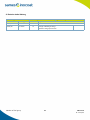
7. Troubleshootings
Symptoms Probable causes Remedies
Powder comes out
in sudden drops
Insufficient fluidization of the powder
Increase fluidization air flow rate
Check the condition of the porous cone,
replace it if it is obstructed.
Insufficient injection air flow rate Increasing the injection air flow rate
Diameter of the powder transport hose unsuitable. Use the hose recommended by Sames.
Absence of the o-ring under the body Put a new o-ring

20
Member of Exel group DRT7170
B - 2023/10
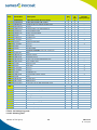
8. Spare parts list
The spare parts are classified in 2 different types:
•1st emergency parts:
The 1st emergency parts are strategic components which are not necessarily consumables but which in case
of failure prohibit the operation of the equipment.
Depending on the production line's commitment and the production rates imposed, the first emergency parts
are not necessarily kept available in the customer's stock.
Indeed, if an interruption of the production flow is possible, storage is not necessary.
On the other hand, if the stop is not possible, the 1st emergency parts will be kept in stock.
•Wearing parts:
Wearing parts are consumable components such as O-rings that undergo regular degradation over time during
normal operation of the installation. It is therefore advisable to replace them according to a defined frequency
and adapted to the operating time of the installation.
The wearing parts must therefore be kept in the customer's stock.
To guarantee an optimal assembly, spare parts must be stored in a temperature close to their
temperature of use. Should the opposite occur, a sufficient waiting time must be observed before the
installation, so that all the elements are assembled in the same temperature.
Pagina se încarcă...
Pagina se încarcă...
Pagina se încarcă...
Pagina se încarcă...
Pagina se încarcă...
Pagina se încarcă...
Pagina se încarcă...
Pagina se încarcă...
Pagina se încarcă...
Pagina se încarcă...
Pagina se încarcă...
Pagina se încarcă...
Pagina se încarcă...
-
 1
1
-
 2
2
-
 3
3
-
 4
4
-
 5
5
-
 6
6
-
 7
7
-
 8
8
-
 9
9
-
 10
10
-
 11
11
-
 12
12
-
 13
13
-
 14
14
-
 15
15
-
 16
16
-
 17
17
-
 18
18
-
 19
19
-
 20
20
-
 21
21
-
 22
22
-
 23
23
-
 24
24
-
 25
25
-
 26
26
-
 27
27
-
 28
28
-
 29
29
-
 30
30
-
 31
31
-
 32
32
-
 33
33


Sames HF Pressure Tank Manual de utilizare
- Tip
- Manual de utilizare
în alte limbi
- English: Sames HF Pressure Tank User manual
Lucrări înrudite
-
Sames Inocart VT, Inocart H Manual de utilizare
-
-
-
-
-
-
-
-
-