
DOC023.98.80249
Polymetron 9610sc/9611sc
07/2016, Edition 3
Maintenance and Troubleshooting
Wartung und Fehlerbehebung
Manutenzione e risoluzione dei problemi
Maintenance et dépannage
Mantenimiento y solución de problemas
Manutenção e resolução de problemas
Údržba a odstraňování problémů
Vedligeholdelse og fejlfinding
Onderhoud en probleemoplossing
Konserwacja i usuwanie usterek
Underhåll och felsökning
Huolto ja vianmääritys
Поддръжка и Oтстраняване на проблеми
Karbantartás és hibaelhárítás
Întreţinerea şi depanarea
Techninė priežiūra ir trikčių šalinimas
Техническое обслуживание и устранение неполадок
Bakım ve Sorun Giderme
Údržba a riešenie problémov
Vzdrževanje in odpravljanje težav
Održavanje i rješavanje problema
Συντήρηση και αντιμετώπιση προβλημάτων
Hooldus ja tõrkeotsing

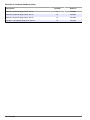
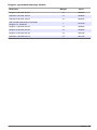
English..............................................................................................................................3
Deutsch.......................................................................................................................... 18
Italiano............................................................................................................................ 35
Français......................................................................................................................... 52
Español.......................................................................................................................... 69
Português...................................................................................................................... 86
Čeština......................................................................................................................... 103
Dansk............................................................................................................................119
Nederlands................................................................................................................. 136
Polski............................................................................................................................ 152
Svenska....................................................................................................................... 168
Suomi............................................................................................................................184
български................................................................................................................... 200
Magyar......................................................................................................................... 217
Română....................................................................................................................... 234
lietuvių kalba...............................................................................................................250
Русский........................................................................................................................266
Türkçe...........................................................................................................................283
Slovenský jazyk......................................................................................................... 299
Slovenski..................................................................................................................... 315
Hrvatski........................................................................................................................ 331
Ελληνικά...................................................................................................................... 347
eesti keel..................................................................................................................... 364
2

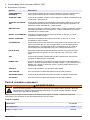
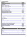
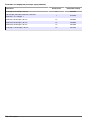
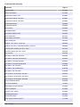
Table of contents
Maintenance schedule on page 3 Replace the analyzer bottles on page 7
Put the analyzer in shutdown mode on page 4 Troubleshooting on page 10
Clean the instrument on page 4 Replacement parts and accessories on page 15
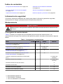
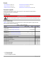
Safety information
Refer to the installation user manual for general safety information, hazard descriptions and
precautionary labels descriptions.
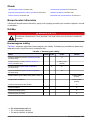
Maintenance
D A N G E R
Multiple hazards. Only qualified personnel must conduct the tasks described in this section of the
document.
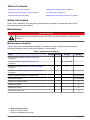
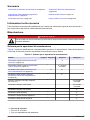
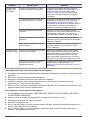
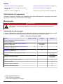
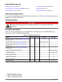
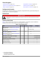
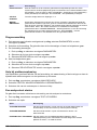
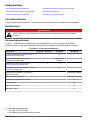
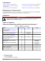
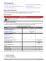
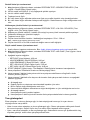
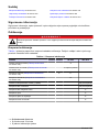
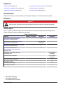
Maintenance schedule
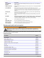
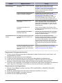
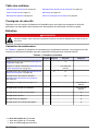
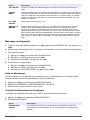
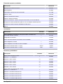
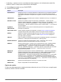
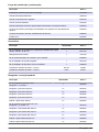
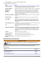
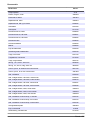
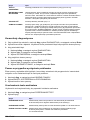
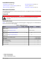
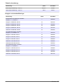
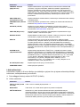
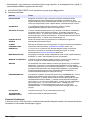
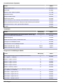
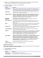
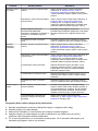
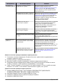
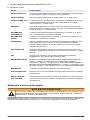
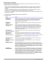
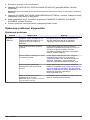
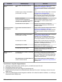
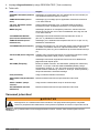
Table 1 shows the recommended schedule of maintenance tasks. Facility requirements and
operating conditions may increase the frequency of some tasks.
Table 1 Maintenance schedule
Task 30 days 60 days 90 days 365 days
Clean external surfaces (Clean the instrument
on page 4).
X
Clean the sample cell (Clean the sample cell
on page 5).
X or as needed
Replace the reagents (Replace the analyzer bottles
on page 7).
X
1
X
2
Replace the standards (Replace the analyzer bottles
on page 7).
X
3
Clean or replace the sample (y-strainer) filter X or as needed
Replace the fan filter X or as needed
Replace the reagent air filter X
Replace the tubing X
Replace the stir bar X
Replace the sample cell X
1
With 10 minute cycles
2
With 15 minute cycles
3
With one calibration per week
English 3

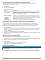
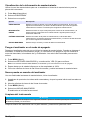
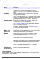
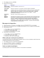
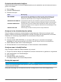
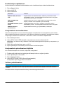
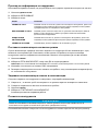
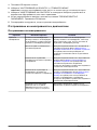
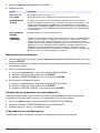
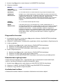
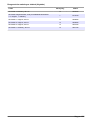
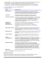
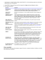
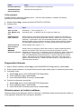
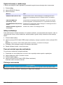
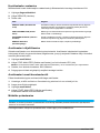
View maintenance information
Use the service menu to view or reset the service history for the instrument parts.
1. Push diag.
2. Select SERVICE.
3. Select an option.
Option Description
SERVICE PART Shows a list of parts and the date of the last service, the date of the next service and
the number of days before the next service is due. Restart the counter for the next
service.
PART INFORMATION Shows the date when each part was put into service and the total time that each part
has been in use. Some parts include additional information.
UPCOMING SERVICE Shows the name of the service part, the date of the last service, the date of the next
service and the number of days before the next service is due.
SERVICE HISTORY Shows the type, date and time of the last service.
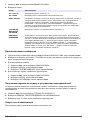
Put the analyzer in shutdown mode
Stop the analyzer before maintenance tasks are started. When the analyzer is stopped, the
colorimeter cell is flushed, then the sample flow, mixer motor, air pump and heater turn off. The
controller menus stay active.
1. Push menu.
2. Select STOP ANALYZER, then YES to confirm.
Note: If START ANALYZER is shown, the analyzer is already in shutdown mode.
3. Wait for the status to show 100% completion.
4. Close the shut-off valves in the sample lines, then complete the maintenance task(s).
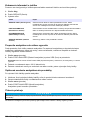
Put the analyzer back into operation
After maintenance tasks are complete, start the analyzer.
1. Make sure that all the tubing is connected and that the lower door is closed and latched.
2. Open the shut-off valves in the sample lines.
3. Push menu.
4. Select START ANALYZER.
The analyzer starts normal operation.
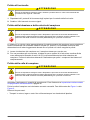
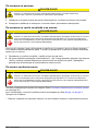
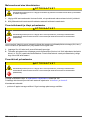
Clean the instrument
N O T I C E
Never use cleaning agents such as turpentine, acetone or similar products to clean the instrument including the
display and accessories.
Clean the exterior of the instrument with a moist cloth and a mild soap solution.
4
English

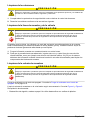
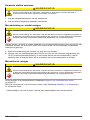
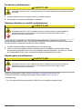
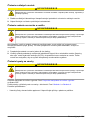
Clean spills
C A U T I O N
Chemical exposure hazard. Dispose of chemicals and wastes in accordance with local, regional and
national regulations.
1. Obey all facility safety protocols for spill control.
2. Discard the waste according to applicable regulations.
Sample line and valve cleanup
C A U T I O N
Chemical exposure hazard. Obey laboratory safety procedures and wear all of the personal protective
equipment appropriate to the chemicals that are handled. Refer to the current safety data sheets
(MSDS/SDS) for safety protocols.
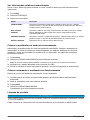
New tubing, valves and other sample conditioning equipment may be contaminated with silicate-
based substances (oils, dust). These may contribute to slightly high readings until they are cleaned.
1. Flush the sample line with sample for one to two hours.
2. For an expedient procedure, inject one to four liters of a dilute caustic solution such as 1N (5%)
sodium hydroxide solution into the front end of the sample line. Force the solution through the
analyzer to clean sample system components.
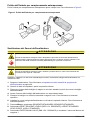
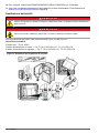
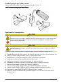
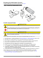
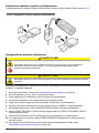
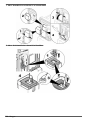
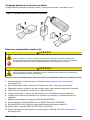
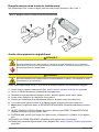
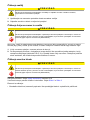
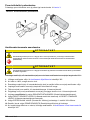
Clean the sample cell
C A U T I O N
Chemical exposure hazard. Obey laboratory safety procedures and wear all of the personal protective
equipment appropriate to the chemicals that are handled. Refer to the current safety data sheets
(MSDS/SDS) for safety protocols.
Put the analyzer in shutdown mode. Refer to Put the analyzer in shutdown mode on page 4.
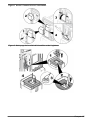
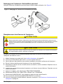
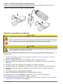
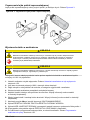
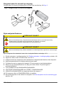
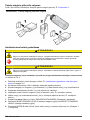
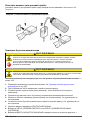
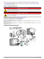
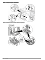
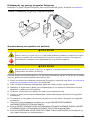
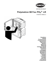
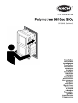
Clean the sample cell in the colorimeter as needed. Refer to Figure 1 and Figure 2.
Items to collect:
• Cotton swabs, wooden or paper. Do not use swabs with plastic sticks.
English
5

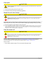
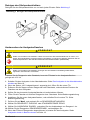
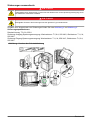
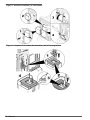
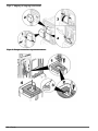
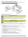
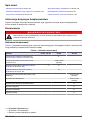
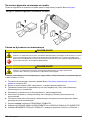
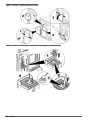
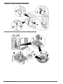
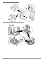
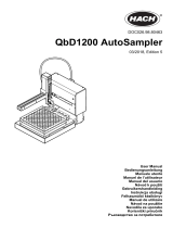
Figure 1 Funnel and colorimeter access
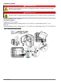
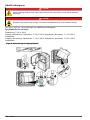
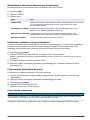
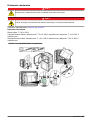
Figure 2 Clean the sample cell and stir bar
6 English

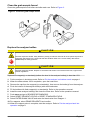
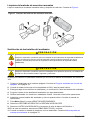
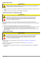
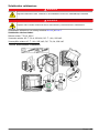
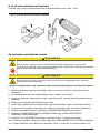
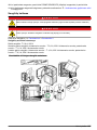
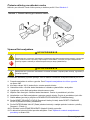
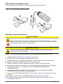
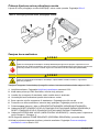
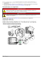
Clean the grab sample funnel
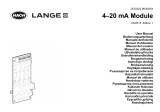
Clean the grab sample funnel before and after each use. Refer to Figure 3.
Figure 3 Clean the grab sample funnel
Replace the analyzer bottles
C A U T I O N
Chemical exposure hazard. Obey laboratory safety procedures and wear all of the personal protective
equipment appropriate to the chemicals that are handled. Refer to the current safety data sheets
(MSDS/SDS) for safety protocols.
C A U T I O N
Chemical exposure hazard. Dispose of chemicals and wastes in accordance with local, regional and
national regulations.
Replace the reagent(s) or standard(s) before the level in the analyzer bottle(s) is less than 10%.
1. Put the analyzer in shutdown mode. Refer to Put the analyzer in shutdown mode on page 4.
2. When the status shows 100% completion, open the lower door.
3. Remove the cap from the reagent(s) or standard(s), then remove the bottle(s) from the analyzer.
4. Flush the interior of the analyzer bottle(s) with deionized water.
5. Fill the bottles with fresh reagent(s) or standard(s). Refer to the operations manual.
6. Install the new analyzer bottle(s) and close the lower door. Refer to the operations manual.
7. Push menu and go to REAGENTS/STANDARDS.
8. Select RESET REAGENT LEVELS or RESET STANDARD LEVELS.
9. Select ENTER BLANK VALUE and enter the blank value from Reagent 1.
10. For reagents, select PRIME REAGENTS and confirm.
11. When the reagent prime is complete, start the analyzer. Refer to Put the analyzer back into
operation on page 4.
English
7

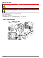
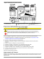
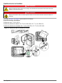
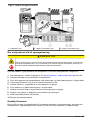
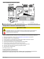
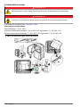
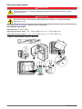
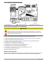
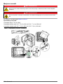
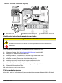
Replace the fuses
D A N G E R
Electrocution hazard. Always remove power to the instrument before making electrical connections.
D A N G E R
Fire hazard. Use the same type and current rating to replace fuses.
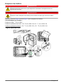
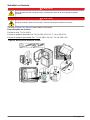
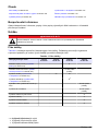
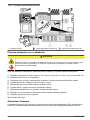
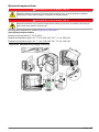
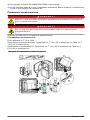
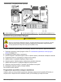
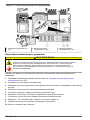
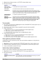
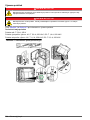
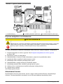
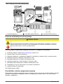
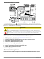
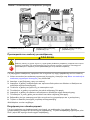
Refer to Figure 4 and Figure 5 to replace the fuses.
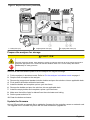
Fuse specifications:
Relay fuse: T 5.0 A, 250 V
Output power fuse: AC: T 5.0 A, 250 VAC; DC: T 1.6 A, 250 VAC
Input power fuse: AC: T 1.6 A, 250 VAC; DC: T 6.3 A, 250 VAC
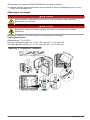
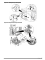
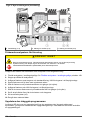
Figure 4 Access cover removal
8 English

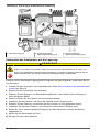
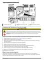
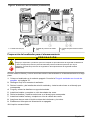
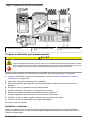
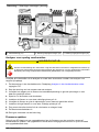
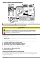
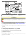
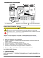
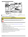
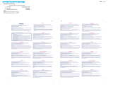
Figure 5 Replace the fuses (continued)
1 Relay fuse (4x) 2 Output power fuse (2x) 3 Input power fuse (2x)
Prepare the analyzer for storage
C A U T I O N
Chemical exposure hazard. Obey laboratory safety procedures and wear all of the personal protective
equipment appropriate to the chemicals that are handled. Refer to the current safety data sheets
(MSDS/SDS) for safety protocols.
Remove all the fluids and the power from the analyzer for long-term storage.
1. Put the analyzer in shutdown mode. Refer to Put the analyzer in shutdown mode on page 4.
2. Stop the flow of sample to the analyzer.
3. Remove the reagent and standard solution bottles and pour the solutions into an applicable drain.
4. Flush and fill the bottles with deionized water.
5. Install the bottles and complete a prime cycle two times.
6. Remove the bottles and pour the solutions into an applicable drain.
7. Install the empty bottles and complete a prime cycle two times.
8. Make sure that all the liquid is drained from the colorimeter and tubing.
9. Set the power switch to off.
10. Clean the bottom enclosure.
Update the firmware
Use an SD card with an upgrade file to update the firmware for the controller, sensor or network card.
The upgrade menu is shown only when the SD card contains an upgrade file.
English
9

1. Install the SD card into the SD card slot.
2. Select SD CARD SETUP from the MAIN MENU.
Note: The SD CARD SETUP option shows only when an SD card is installed.
3. Select UPGRADE SOFTWARE and confirm. Select the device and upgrade version, if applicable.
4. When the upgrade is complete, the display shows TRANSFER COMPLETE. Remove the SD
card.
5. Restart the instrument for the upgrade to take effect.
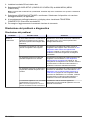
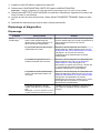
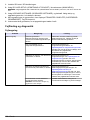
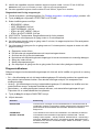
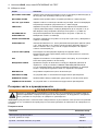
Troubleshooting and diagnostics
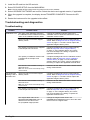
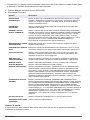
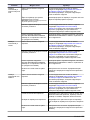
Troubleshooting
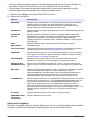
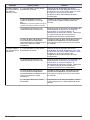
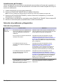
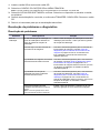
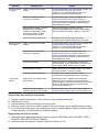
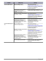
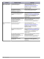
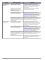
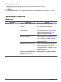
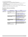
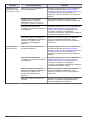
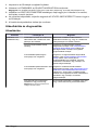
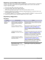
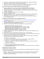
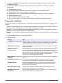
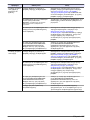
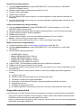
Problem Possible cause Solution
Calibration error The value of the calibration solution in
the calibration menu is different from the
value on the calibration solution bottle.
Change the calibration solution value in the
calibration menu to show the value that is on the
calibration solution bottle.
There is a leak in one of the reagent
delivery valves.
Complete the diagnostic test for reagent delivery
valves. Refer to Diagnostic test for reagent delivery
valves on page 11. If a leak is found, replace the
applicable reagent delivery valve.
The quantity of reagent that is supplied
to the sample cell is incorrect.
Complete the diagnostic test for reagent delivery.
Refer to Diagnostic test for reagent delivery
on page 11. If the reagent delivery is incorrect,
look for a blockage in the tubing or replace the
applicable solenoid valve.
The quantity of calibration solution that
is supplied to the sample cell is
incorrect.
Complete the diagnostic test for calibration solution
delivery. Refer to Diagnostic test for calibration
solution delivery on page 12. If the calibration
solution delivery is incorrect, look for a blockage in
the tubing or replace the applicable solenoid valve.
The stir bar is not installed correctly or
does not move.
Note: The stir bar moves intermittently during
measurements.
Install the stir bar. Make sure that the stir bar moves
during measurements.
The instrument
reading is low or
less than zero.
There is a leak in one of the reagent
delivery valves.
Complete the diagnostic test for reagent delivery
valves. Refer to Diagnostic test for reagent delivery
valves on page 11. If a leak is found, replace the
applicable reagent delivery valve.
The stir bar is not installed correctly or
does not move.
Note: The stir bar moves intermittently during
measurements.
Install the stir bar. Make sure that the stir bar moves
during measurements.
The quantity of reagent that is supplied
to the sample cell is incorrect.
Complete the diagnostic test for reagent delivery.
Refer to Diagnostic test for reagent delivery
on page 11. If the reagent delivery is incorrect,
look for a blockage in the tubing or replace the
applicable solenoid valve.
The reagent blank value in the
REAGENTS/STANDARDS menu is
different from the value on the
R1 (molybdate reagent) bottle.
Change the reagent blank value in the
REAGENTS/STANDARDS menu to show the value
that is on the R1 reagent bottle.
10 English

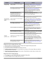
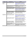
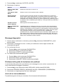
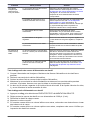
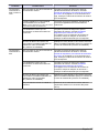
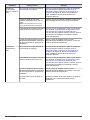
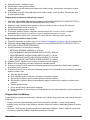
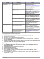
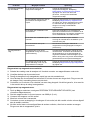
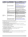
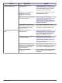
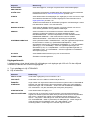
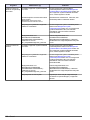
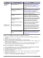
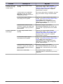
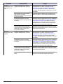
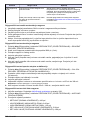
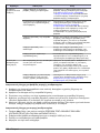
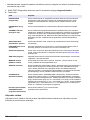
Problem Possible cause Solution
The instrument
reading is high.
There is a leak in one of the reagent
delivery valves.
Complete the diagnostic test for reagent delivery
valves. Refer to Diagnostic test for reagent delivery
valves on page 11. If a leak is found, replace the
applicable reagent delivery valve.
The quantity of reagent that is supplied
to the sample cell is incorrect.
Complete the diagnostic test for reagent delivery.
Refer to Diagnostic test for reagent delivery
on page 11. If the reagent delivery is incorrect,
look for a blockage in the tubing or replace the
applicable solenoid valve.
The reagent blank value in the
REAGENTS/STANDARDS menu is
different from the value on the
R1 (molybdate reagent) bottle.
Change the reagent blank value in the
REAGENTS/STANDARDS menu to show the value
that is on the R1 reagent bottle.
There is a blue stain on the sample cell. Replace the sample cell. Use the reagent set with
the modified R2 (citric acid) reagent.
The instrument
readings are not
stable.
There is a leak in one of the reagent
delivery valves.
Complete the diagnostic test for reagent delivery
valves. Refer to Diagnostic test for reagent delivery
valves on page 11. If a leak is found, replace the
applicable reagent delivery valve.
The quantity of reagent that is supplied
to the sample cell is incorrect.
Complete the diagnostic test for reagent delivery.
Refer to Diagnostic test for reagent delivery
on page 11. If the reagent delivery is incorrect,
look for a blockage in the tubing or replace the
applicable solenoid valve.
There are bubbles in the sample cell. Look for bubbles in the sample cell. If there are
bubbles in the sample cell, rinse the sample cell. If
the readings do not become stable, replace the
sample cell.
There are bubbles on the stir bar. Look for bubbles on the stir bar. If there are bubbles
on the stir bar, replace the stir bar.
There is a blue stain on the sample cell. Replace the sample cell. Use the reagent set with
the modified R2 (citric acid) reagent.
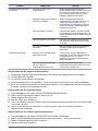
Reagent
pressure is low.
A bottle cap is not on tightly or does not
make a good seal.
Remove the bottle caps. Clean the rim of the
bottles. Examine the inner surfaces of the bottle
caps for unwanted material. Fully tighten the bottle
caps on the bottles. Make sure the fittings are tight
on top of the bottle caps.
There is a leak or a bad seal in one of
the reagent bottles or tubes.
Complete the diagnostic test for low reagent
pressure. Refer to Diagnostic test for low reagent
pressure on page 12.
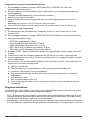
Diagnostic test for reagent delivery valves
1. Remove power to the analyzer. Keep the sample and reagent bottles pressurized.
2. Remove the cover from the sample cell.
3. Dry the tubes that are attached to the sample cell cover.
4. Hold the sample cell cover above a dry towel for a minimum of 10 minutes. Make sure that the
tubes do not touch the towel.
5. After 10 minutes, look for fluid to fall from a tube. If fluid falls from a tube, there is a leak in the
valve that is plumbed to the tube.
Diagnostic test for reagent delivery
1. Push diag, then select PERFORM TEST>REAGENT DELIVERY.
2. Set each reagent valve to supply 2000 µL (2 mL).
English
11

3. Collect the reagent from each valve.
4. Measure the volume that was collected.
5. If one valve dispenses less volume than the other valves, look for a blockage in the tubing or
valve.
6. If one valve dispenses more volume than the other valves, replace the valve. Make sure that the
reagent pressure is correct.
Diagnostic test for calibration solution delivery
1. Push diag, then select PERFORM TEST>CAL SOL. DELIVERY.
2. Set the calibration solution valve(s) to supply solution for 1 minute (60 seconds).
3. Collect the calibration solution from the valve(s).
4. Measure the volume that was collected.
5. Compare the measured volume to the specified volume for 1 minute: 55 mL to 300 mL.
Note: The volume collected in 1 minute is the flow rate.
6. If the measured volume is not between 55 mL and 300 mL, replace the applicable valve.
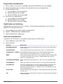
Diagnostic test for low reagent pressure
1. Put the analyzer in shutdown mode. Refer to Put the analyzer in shutdown mode on page 4.
2. Push diag, then select PERFORM TEST>AIR PUMP.
3. Change the settings that follow.
• SETPOINT: 4.00 psi
• LOW DEADBAND: 0.00 psi
• HIGH DEADBAND: 1.00 psi
• SET LOW VALUE: 5.00 psi
• SET HIGH VALUE: 6.00 psi
4. Select START. The test starts. The reagent bottles become fully pressurized.
5. Monitor how frequently the air pump operates during a 5-minute period.
6. If the air pump operates only one time in 5 minutes, the reagent pressure is good. Put the
analyzer back into operation.
7. If the air pump operates more than one time during a 5-minute period, stop the test and complete
the steps that follow.
a. Open the lower door.
b. Fully tighten the caps on the reagent bottles and compression nuts.
c. Make sure that all of the tubes are installed correctly.
d. Make sure that the air manifold fittings are installed correctly and are fully tightened.
e. Close the lower door.
f. Start the air pump test again.
g. If the air pump operates more than one time in 5 minutes, more inspection is necessary.
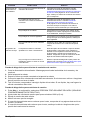
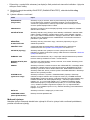
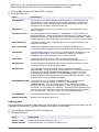
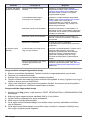
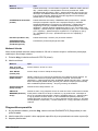
Diagnostic indicators
The display background and the status indicator light will change to red when an error occurs and to
yellow when a warning occurs.
• Error—red display background and status indicator light. A significant problem occurred that
affects the instrument operation. The current measurement stops and the analyzer goes into
shutdown mode.
• Warning—yellow display background and status indicator light. An event occurred that can cause
a future problem. The analyzer continues to operate.
12
English

• Reminders—wrench symbol shows on the display and yellow status indicator light. The time for a
maintenance task has passed.
1. Push diag to access the DIAG/TEST menu.
2. Select an option.
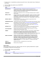
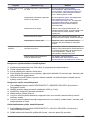
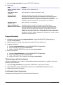
Option Description
DIAGNOSTICS Shows the errors and warnings that currently are on the instrument or on the installed
modules. The analyzer is in operation with the active warnings or reminders until they
are acknowledged or reset. Then, the display background will return to white.
PROGNOSYS Shows the variables which trigger the service indicator and the measurement health
indicator on the display.
CURRENT STATUS Shows the current instrument statuses that follow: OPERATION—Current
measurement mode. SAMPLE CHANNEL—Current sample channel. STEP STATUS
—Current step in the measurement cycle. STEP TIME—Step time remaining.
MINUTES LEFT—Minutes left in current step. COMPLETION—% completed of the
measurement cycle.
ANALYZER HELP Shows all possible errors, warnings and reminders with troubleshooting hints.
PERFORM TEST Examines individual parts of the analyzer. Refer to Start an analyzer test on page 14
for more details about the individual test options.
OUTPUTS Shows the current status of the 4–20 mA and relay outputs with the options to
examine, hold and simulate the outputs. Refer to Output options on page 13 for more
information.
VIEW LED Illuminates the colorimeter cell for improved viewing during troubleshooting. The cell
can be illuminated from 1 to 999 seconds.
MODBUS STATS Shows the status of the Modbus ports: sensor, controller, network and service. Shows
the number of good and bad transmissions.
SERVICE Shows the service parts information and the history. SERVICE PART—shows the last
and the next service date and the remaining days. PART INFORMATION—Shows the
replaced part and the current run time. UPCOMING SERVICE—Shows the next part
which needs to be replaced. SERVICE HISTORY—Shows the date and time of the
replaced parts.
SYSTEM DATA Shows the system information. TEMPERATURE—Shows the measured temperature
of the A/D device in Celsius (C). POWER SOURCE FREQUENCY—Shows the line
power frequency (Hz). POWER SOURCE VOLTAGE—Shows the line power voltage
(V). 12 V VOLTAGE—Shows the measured power supply voltage (V DC). 3.3 V
VOLTAGE—Shows the measured regulated 3.3 V supply (V DC). 12 V CURRENT—
Shows the measured 12 V power supply current (Amps).
I2C DATA Shows the display information (I
2
C) and the version number.
OVERFEED RESET Resets the overfeed timer.
Output options
The output menu shows the current status of the 4–20 mA and relay outputs with the options to
examine, hold and simulate the outputs.
1. Push diag and select OUTPUTS.
2. Select an option.
Option Description
TEST 4–20 mA Examines the 4–20 mA outputs from 1–4.
TEST RELAY Examines the relays A–D. Sets the relays to on or off.
English 13

Option Description
HOLD OUTPUTS Sets the value that the controller sends to an external system for a defined period of
time. After this time period, the instrument reports again real time values. ACTIVATION
—Launches or releases. SET OUTMODE—Hold Outputs (default) or Transfer Outputs.
SET CHANNELS—All (default) or analyzer.
OUTPUT
STATUS
Shows the current status outputs 1–4.
SIMULATE
MEASURE
Shows only when a sensor or module is connected. After the sim value is entered, the
controller outputs this value as if it was the value sent from the sensor. The simulation
stops after the user exits the screen. SELECT SOURCE—Select the module. The footer
shows the current selected source. SET PARAMETER—Sets the parameter for the
source measurement. The footer shows the current selected source. SET SIM VALUE—
Enter the sim value. The footer shows the entered value.
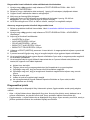
Diagnostic messages
1. When an indicator is shown, push diag, select DIAGNOSTICS, then push enter.
2. Select the error message. The user can acknowledge the error or go to the help screen.
3. To acknowledge the error:
1. Push diag, then select DIAGNOSTICS.
2. Select the error, then push enter.
3. Select ACKNOWLEDGE, then push enter.
4. To go to the help screen:
1. Push diag, then select DIAGNOSTICS.
2. Select the error, then push enter.
3. Select VIEW HELP, then push enter.
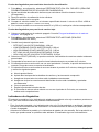
Get troubleshooting help
The help screen gives a definition of error, warning or reminder messages and can give associated
tasks to correct the problem.
1. Push diag, then select ANALYZER HELP.
2. Select ERRORS, WARNINGS or REMINDERS.
3. Select one of the topics from the help menu.
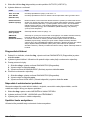
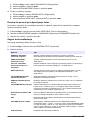
Start an analyzer test
The user can complete tests to check the analyzer operation.
1. Push diag, then select PERFORM TEST.
2. Select an option.
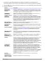
Option Description
REAGENT DELIVERY Set each reagent valve to on for a time delivery (50 milliseconds to 65 seconds)
or for a volume delivery (20 to 9,999 µL).
SAMPLE DELIVERY Set each sample valve to on for a sample delivery of 1 to 9999 seconds.
CAL SOL. DELIVERY Set the cal std valve to on for a calibration solution delivery into the colorimeter
cell. Set the duration on from 1 to 9999 seconds.
MIXER Set to on for a clockwise or counterclockwise (CCW/CW) rotation. The revolution
per minute (RPM) can be set from 10 to 500 rpm. On time can be set from 1 to
9999 seconds.
14 English

Option Description
COLORIMETER
HEATER
Set the colorimeter heater settings from 20–60 °C (68–140 °F). The measured
value is shown.
SAMPLE HEATER Set the sample heater settings from 20–60 °C (68–140 °F). The measured value
is shown.
COLORIMETER Start an automatic test which increases the optical LED duty cycle in 5%
increments. This starts from 0% until the output reaches the saturation. The A2D
counts are shown for 0%, then % before the saturation and the first saturation
value (%).
STATUS LED Examine the front panel status LED indicator. The test cycles continuously until
interrupted: off, red, green, yellow.
A2D Set the colorimeter LED intensity to examine the cell transmittance for the A2D
output.
AIR PUMP Change and control the air pressure. SET SETPOINT—Range: 1–9.99 psi. LOW
and HIGH DEADBAND—Range: 0–1 psi. SET LOW and HIGH VALUE—Range:
5–99.99 psi. START—Start the air pump with the entered settings.
FAN Set to adjust the fan duty cycle.
ANALYZER TYPE For use by manufacturer technical support only.
SELECT SCRIPT Toggle between normal instrument script and test script.
SET CHANNELS For use by manufacturer technical support only.
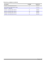
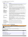
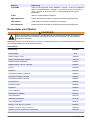
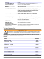
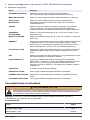
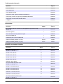
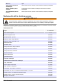
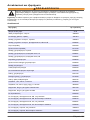
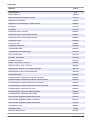
Replacement parts and accessories
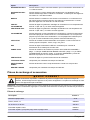
W A R N I N G
Personal injury hazard. Use of non-approved parts may cause personal injury, damage to the
instrument or equipment malfunction. The replacement parts in this section are approved by the
manufacturer.
Note: Product and Article numbers may vary for some selling regions. Contact the appropriate distributor or refer to
the company website for contact information.
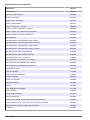
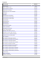
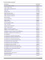
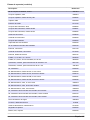
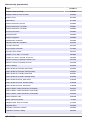
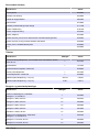
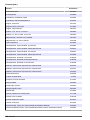
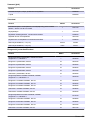
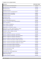
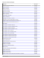
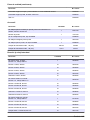
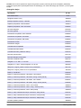
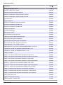
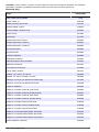
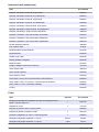
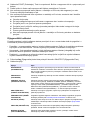
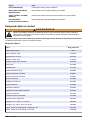
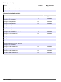
Replacement parts
Description Item no.
Air pump filter 2718
Bottle, reagent, 2 liter 9395000
Bottle assembly kit, 5 bottles 2037601
Capillary assembly, silica 6786901
Capillary assembly, HR and LR phosphate 6786902
Cell cap 6767800
Cell shroud 6773100
Colorimeter assembly, silica 6786800
Colorimeter assembly, LR phosphate 6786801
Colorimeter assembly, HR phosphate 6786802
Colorimeter cell 6768000
Colorimeter cover 6766900
Fan assembly 6789800
English 15

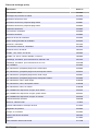
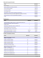
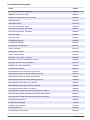
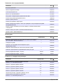
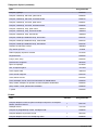
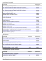
Replacement parts (continued)
Description Item no.
Fan filter plug 6789300
Fan filter replacement kit 6789100
Funnel, colorimeter 6767100
Funnel cover, colorimeter 6773500
Funnel, reagent bottle 2264472
Fuse, 1.6 A, 250 V, 5 x 20 mm 5208300
Fuse, 5 A, 250 V, slow-blow, 5 x 20 mm 4693800
Heater, sample, for 120/240 VAC instruments 9391700
Heater, sample, for 24 VDC instruments 9391800
Kit, Installation 6783500
Kit, Maintenance, HR phosphate, single channel 6788309
Kit, Maintenance, HR phosphate, two/four channel 6788310
Kit, Maintenance, LR phosphate, single channel 6788307
Kit, Maintenance, LR phosphate, two/four channel 6788308
Kit, Maintenance, silica, single channel 6788304
Kit, Maintenance, silica, two/four channel 6788305
Kit, Maintenance, silica, six channel 6788306
Kit, Sequencer line installation, two channel 6785102
Kit, Sequencer line installation, four channel 6785104
Kit, Sequencer line installation, six channel 6785106
Leak detector board 6562800
Plug, air manifold 014659
Power cord, North American 9179700
Pressure regulator 6782900
Pump, air, assembly 6784500
Reagent bottle tray 9640400
Stir bar 6772600
Tool, flangeless nut extender 5117400
Valve, air relief 6783700
Valve, reagent delivery 6783700
Valve, grab sample 6794300
Valve, pinch, sample, only for instruments with sequencers 6786400
Valve assembly, pinch, for use with any of chemistry standards 6786300
Valve assembly, sample, single channel analyzer 6786500
Y strainer 6784800
16 English

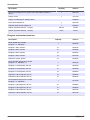
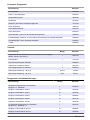
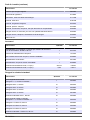
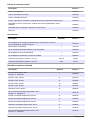
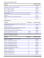
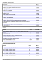
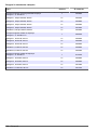
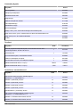
Accessories
Description Quantity Item no.
Panel mount adaptor kit to replace 921x with 5500sc, 9610sc or
9611sc
1 6787100
Sample cooler 1 1757700
Sample conditioning kit, stainless steel 6786600
Smart probe adaptor kit 1 9321000
Stainless steel sample adapter kit 1 6786600
Sodium hydroxide solution, 1 N (5%) 900 mL 104553
Sodium hydroxide solution, 1 N (5%) 3.60 L 104517
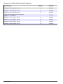
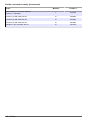
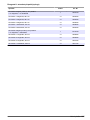
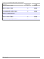
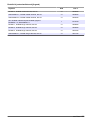
Reagents and standard solutions
Description Quantity Item no.
Silica reagent kit, includes:
Reagent 1–4, Standard 1
1 2035600
Reagent 1 Silica, 9610sc 2 L 2035702
Reagent 2 Silica, 9610sc 2 L 2035802
Reagent 3 Silica, 9610sc 2 L 2036002
Reagent 4 Silica, 9610sc 2 L 2037502
Standard 1 Silica, 9610sc 2 L 2035902
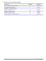
LR Phosphate reagent kit, includes:
Reagent 1–3, Standard 1-2
1 2036100
Reagent 1 LR Phosphate, 9611sc 2 L 2036202
Reagent 2 LR Phosphate, 9611sc 2 L 2036302
Reagent 3 LR Phosphate, 9611sc 2 L 2036502
Standard 1 LR Phosphate, 9611sc 2 L 2036602
Standard 2 LR Phosphate, 9611sc 2 L 2036402
HR Phosphate reagent kit, includes:
Reagent 1–3, Standard 1
1 6776100
Reagent 1 HR Phosphate, 9611sc 2 L 2036802
Reagent 2 HR Phosphate, 9611sc 2 L 2036902
Reagent 3 HR Phosphate, 9611sc 2 L 2037002
Standard 1 HR Phosphate, 9611sc 2 L 2037102
English 17

Inhaltsverzeichnis
Wartungsplan auf Seite 18 Austauschen der Analysatorflaschen auf Seite 22
Den Analysator in den Abschaltmodus schalten
auf Seite 19
Fehlerbehebung auf Seite 25
Reinigen des Geräts auf Seite 19 Ersatzteile und Zubehör auf Seite 31
Sicherheitshinweise
Allgemeine Sicherheitshinweise, Gefahren- und Warnetikettenbeschreibungen finden Sie im
Installationshandbuch.
Wartung
G E F A H R
Mehrere Gefahren. Nur qualifiziertes Personal sollte die in diesem Kapitel des Dokuments
beschriebenen Aufgaben durchführen.
Wartungsplan
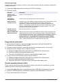
Tabelle 1 zeigt den empfohlenen Wartungsplan. Je nach Anforderungen der Anlage und den
Betriebsbedingungen kann es erforderlich sein, einige Aufgaben häufiger auszuführen.
Tabelle 1 Wartungsplan
Maßnahme 30 Tage 60 Tage 90 Tage 365 Tage
Reinigen der externen Oberflächen (Reinigen des
Geräts auf Seite 19).
X
Reinigen der Probenküvette (Reinigen der
Probenzelle auf Seite 20).
X oder nach
Bedarf
Ersetzen der Reagenzien (Austauschen der
Analysatorflaschen auf Seite 22).
X
1
X
2
Ersetzen der Standards (Austauschen der
Analysatorflaschen auf Seite 22).
X
3
Reinigen oder Ersetzen des Probenfilters (Y-Sieb) X oder nach Bedarf
Austausch der Luftfilter X oder nach Bedarf
Ersetzen des Reagenzluftfilters X
Ersetzen der Schläuche X
Ersetzen des Rührbolzens X
Ersetzen der Probenzelle X
1
Bei 10-Minuten-Zyklen
2
Bei 15-Minuten-Zyklen
3
Bei einer Kalibrierung pro Woche
18 Deutsch

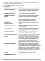
Wartungsinformationen anzeigen
Verwenden Sie das Menü WARTUNG, um den Wartungsverlauf für die Geräteteile anzuzeigen oder
zurückzusetzen.
1. Drücken Sie auf Diag.
2. Wählen Sie WARTUNG.
3. Wählen Sie eine Option.
Optionen Beschreibung
TEIL WARTEN Zeigt eine Liste mit Teilen und das Datum der zuletzt durchgeführten Wartung, das
Datum der nächsten Wartung und die Anzahl von Tagen bis zur nächsten fälligen
Wartung an. Starten Sie den Zähler für die nächste Wartung neu.
TEILEINFORMATION Zeigt das Datum an, an dem die einzelnen Teile in Betrieb genommen wurden, und
die Gesamtdauer, während der die einzelnen Teile betrieben wurden. Bei einigen
Teilen werden zusätzliche Informationen angezeigt.
NÄCHSTE WARTUNG Zeigt den Namen des Wartungsteils, das Datum der zuletzt durchgeführten
Wartung, das Datum der nächsten Wartung und die Anzahl von Tagen bis zur
nächsten fälligen Wartung an.
WARTUNGSVERL. Zeigt den Typ, das Datum und die Uhrzeit der letzten Wartung an.
Den Analysator in den Abschaltmodus schalten
Stoppen Sie den Analysator vor Beginn von Wartungsaufgaben. Wenn der Analysator gestoppt ist,
wird die Kolorimeterzelle gespült, danach werden der Probendurchfluss, der Mischermotor, die
Druckluftpumpe und die Heizung ausgeschaltet. Die Controller-Menüs bleiben aktiv.
1. Drücken Sie auf Menü.
2. Wählen Sie ANALYSATOR STOPPEN und dann JA, um den Vorgang zu bestätigen.
Hinweis: Wenn ANALYSATOR STARTEN angezeigt wird, befindet sich der Analysator bereits im
Abschaltmodus.
3. Warten Sie, bis der Status „100 % abgeschlossen“ anzeigt.
4. Schließen Sie die Absperrventile in den Probenleitungen, und schließen Sie dann die
Wartungsarbeiten ab.
Analysator wieder in Betrieb nehmen
Starten Sie nach Abschluss der Wartungsaufgaben den Analysator.
1. Stellen Sie sicher, dass alle Schläuche angeschlossen sind und dass die untere Tür geschlossen
und verriegelt ist.
2. Öffnen Sie die Absperrventile in den Probenleitungen.
3. Drücken Sie auf Menü.
4. Wählen Sie ANALYSATOR STARTEN.
Der Analysator startet den Normalbetrieb.
Reinigen des Geräts
H I N W E I S
Verwenden Sie zum Reinigen des Geräts, einschließlich von Display und Zubehör, keine Reinigungsmittel wie
Terpentin, Azeton oder ähnliche Produkte.
Reinigen Sie das Gerät mit einer milden Seifenlösung und einem feuchten Tuch.
Deutsch
19

Reinigen von Spritzern
V O R S I C H T
Gefahr von Kontakt mit Chemikalien. Entsorgen Sie Chemikalien und Abfälle gemäß lokalen,
regionalen und nationalen Vorschriften.
1. Befolgen Sie alle örtlichen Sicherheitsprotokolle zur Verschüttungskontrolle
2. Entsorgen Sie die Abfälle gemäß den zutreffenden Vorschriften.
Reinigung der Probenleitungen und Ventile
V O R S I C H T
Gefahr von Kontakt mit Chemikalien. Halten Sie sich an die Sicherheitsmaßnahmen im Labor, und
tragen Sie Schutzkleidung entsprechend den Chemikalien, mit denen Sie arbeiten. Beachten Sie die
Sicherheitsprotokolle in den aktuellen Materialsicherheitsdatenblättern (MSDS/SDB).
Neue Schläuche, Ventile und andere Probenaufbereitungsgeräte können mit Substanzen auf
Kieselsäurebasis (Öle, Staub) verschmutzt sein. Diese können zu etwas erhöhten Messwerten
führen, bis sie gereinigt wurden.
1. Spülen Sie ein bis zwei Stunden lang die Probenleitung mit der Probe.
2. Hierfür wird empfohlen, ein bis vier Liter einer verdünnten Lauge, beispielsweis eine 1N-
Natriumhydroxidlösung (5 %), in das vordere Ende der Probenleitung zu injizieren. Forcieren Sie
die Lösung durch den Analysator, um die Bauteile des Probensystems zu reinigen.
Reinigen der Probenzelle
V O R S I C H T
Gefahr von Kontakt mit Chemikalien. Halten Sie sich an die Sicherheitsmaßnahmen im Labor, und
tragen Sie Schutzkleidung entsprechend den Chemikalien, mit denen Sie arbeiten. Beachten Sie die
Sicherheitsprotokolle in den aktuellen Materialsicherheitsdatenblättern (MSDS/SDB).
Schalten Sie den Analysator in den Abschaltmodus. Siehe Den Analysator in den Abschaltmodus
schalten auf Seite 19.
Reinigen Sie nach Bedarf die Probenküvette im Kolorimeter. Siehe Abbildung 1 und Abbildung 2.
Zusätzlich erforderliche Artikel:
• Wattestäbchen mit Holz- oder Papierstab. Verwenden Sie keine Wattestäbchen mit
Kunststoffröhrchen.
20
Deutsch
Pagina se încarcă...
Pagina se încarcă...
Pagina se încarcă...
Pagina se încarcă...
Pagina se încarcă...
Pagina se încarcă...
Pagina se încarcă...
Pagina se încarcă...
Pagina se încarcă...
Pagina se încarcă...
Pagina se încarcă...
Pagina se încarcă...
Pagina se încarcă...
Pagina se încarcă...
Pagina se încarcă...
Pagina se încarcă...
Pagina se încarcă...
Pagina se încarcă...
Pagina se încarcă...
Pagina se încarcă...
Pagina se încarcă...
Pagina se încarcă...
Pagina se încarcă...
Pagina se încarcă...
Pagina se încarcă...
Pagina se încarcă...
Pagina se încarcă...
Pagina se încarcă...
Pagina se încarcă...
Pagina se încarcă...
Pagina se încarcă...
Pagina se încarcă...
Pagina se încarcă...
Pagina se încarcă...
Pagina se încarcă...
Pagina se încarcă...
Pagina se încarcă...
Pagina se încarcă...
Pagina se încarcă...
Pagina se încarcă...
Pagina se încarcă...
Pagina se încarcă...
Pagina se încarcă...
Pagina se încarcă...
Pagina se încarcă...
Pagina se încarcă...
Pagina se încarcă...
Pagina se încarcă...
Pagina se încarcă...
Pagina se încarcă...
Pagina se încarcă...
Pagina se încarcă...
Pagina se încarcă...
Pagina se încarcă...
Pagina se încarcă...
Pagina se încarcă...
Pagina se încarcă...
Pagina se încarcă...
Pagina se încarcă...
Pagina se încarcă...
Pagina se încarcă...
Pagina se încarcă...
Pagina se încarcă...
Pagina se încarcă...
Pagina se încarcă...
Pagina se încarcă...
Pagina se încarcă...
Pagina se încarcă...
Pagina se încarcă...
Pagina se încarcă...
Pagina se încarcă...
Pagina se încarcă...
Pagina se încarcă...
Pagina se încarcă...
Pagina se încarcă...
Pagina se încarcă...
Pagina se încarcă...
Pagina se încarcă...
Pagina se încarcă...
Pagina se încarcă...
Pagina se încarcă...
Pagina se încarcă...
Pagina se încarcă...
Pagina se încarcă...
Pagina se încarcă...
Pagina se încarcă...
Pagina se încarcă...
Pagina se încarcă...
Pagina se încarcă...
Pagina se încarcă...
Pagina se încarcă...
Pagina se încarcă...
Pagina se încarcă...
Pagina se încarcă...
Pagina se încarcă...
Pagina se încarcă...
Pagina se încarcă...
Pagina se încarcă...
Pagina se încarcă...
Pagina se încarcă...
Pagina se încarcă...
Pagina se încarcă...
Pagina se încarcă...
Pagina se încarcă...
Pagina se încarcă...
Pagina se încarcă...
Pagina se încarcă...
Pagina se încarcă...
Pagina se încarcă...
Pagina se încarcă...
Pagina se încarcă...
Pagina se încarcă...
Pagina se încarcă...
Pagina se încarcă...
Pagina se încarcă...
Pagina se încarcă...
Pagina se încarcă...
Pagina se încarcă...
Pagina se încarcă...
Pagina se încarcă...
Pagina se încarcă...
Pagina se încarcă...
Pagina se încarcă...
Pagina se încarcă...
Pagina se încarcă...
Pagina se încarcă...
Pagina se încarcă...
Pagina se încarcă...
Pagina se încarcă...
Pagina se încarcă...
Pagina se încarcă...
Pagina se încarcă...
Pagina se încarcă...
Pagina se încarcă...
Pagina se încarcă...
Pagina se încarcă...
Pagina se încarcă...
Pagina se încarcă...
Pagina se încarcă...
Pagina se încarcă...
Pagina se încarcă...
Pagina se încarcă...
Pagina se încarcă...
Pagina se încarcă...
Pagina se încarcă...
Pagina se încarcă...
Pagina se încarcă...
Pagina se încarcă...
Pagina se încarcă...
Pagina se încarcă...
Pagina se încarcă...
Pagina se încarcă...
Pagina se încarcă...
Pagina se încarcă...
Pagina se încarcă...
Pagina se încarcă...
Pagina se încarcă...
Pagina se încarcă...
Pagina se încarcă...
Pagina se încarcă...
Pagina se încarcă...
Pagina se încarcă...
Pagina se încarcă...
Pagina se încarcă...
Pagina se încarcă...
Pagina se încarcă...
Pagina se încarcă...
Pagina se încarcă...
Pagina se încarcă...
Pagina se încarcă...
Pagina se încarcă...
Pagina se încarcă...
Pagina se încarcă...
Pagina se încarcă...
Pagina se încarcă...
Pagina se încarcă...
Pagina se încarcă...
Pagina se încarcă...
Pagina se încarcă...
Pagina se încarcă...
Pagina se încarcă...
Pagina se încarcă...
Pagina se încarcă...
Pagina se încarcă...
Pagina se încarcă...
Pagina se încarcă...
Pagina se încarcă...
Pagina se încarcă...
Pagina se încarcă...
Pagina se încarcă...
Pagina se încarcă...
Pagina se încarcă...
Pagina se încarcă...
Pagina se încarcă...
Pagina se încarcă...
Pagina se încarcă...
Pagina se încarcă...
Pagina se încarcă...
Pagina se încarcă...
Pagina se încarcă...
Pagina se încarcă...
Pagina se încarcă...
Pagina se încarcă...
Pagina se încarcă...
Pagina se încarcă...
Pagina se încarcă...
Pagina se încarcă...
Pagina se încarcă...
Pagina se încarcă...
Pagina se încarcă...
Pagina se încarcă...
Pagina se încarcă...
Pagina se încarcă...
Pagina se încarcă...
Pagina se încarcă...
Pagina se încarcă...
Pagina se încarcă...
Pagina se încarcă...
Pagina se încarcă...
Pagina se încarcă...
Pagina se încarcă...
Pagina se încarcă...
Pagina se încarcă...
Pagina se încarcă...
Pagina se încarcă...
Pagina se încarcă...
Pagina se încarcă...
Pagina se încarcă...
Pagina se încarcă...
Pagina se încarcă...
Pagina se încarcă...
Pagina se încarcă...
Pagina se încarcă...
Pagina se încarcă...
Pagina se încarcă...
Pagina se încarcă...
Pagina se încarcă...
Pagina se încarcă...
Pagina se încarcă...
Pagina se încarcă...
Pagina se încarcă...
Pagina se încarcă...
Pagina se încarcă...
Pagina se încarcă...
Pagina se încarcă...
Pagina se încarcă...
Pagina se încarcă...
Pagina se încarcă...
Pagina se încarcă...
Pagina se încarcă...
Pagina se încarcă...
Pagina se încarcă...
Pagina se încarcă...
Pagina se încarcă...
Pagina se încarcă...
Pagina se încarcă...
Pagina se încarcă...
Pagina se încarcă...
Pagina se încarcă...
Pagina se încarcă...
Pagina se încarcă...
Pagina se încarcă...
Pagina se încarcă...
Pagina se încarcă...
Pagina se încarcă...
Pagina se încarcă...
Pagina se încarcă...
Pagina se încarcă...
Pagina se încarcă...
Pagina se încarcă...
Pagina se încarcă...
Pagina se încarcă...
Pagina se încarcă...
Pagina se încarcă...
Pagina se încarcă...
Pagina se încarcă...
Pagina se încarcă...
Pagina se încarcă...
Pagina se încarcă...
Pagina se încarcă...
Pagina se încarcă...
Pagina se încarcă...
Pagina se încarcă...
Pagina se încarcă...
Pagina se încarcă...
Pagina se încarcă...
Pagina se încarcă...
Pagina se încarcă...
Pagina se încarcă...
Pagina se încarcă...
Pagina se încarcă...
Pagina se încarcă...
Pagina se încarcă...
Pagina se încarcă...
Pagina se încarcă...
Pagina se încarcă...
Pagina se încarcă...
Pagina se încarcă...
Pagina se încarcă...
Pagina se încarcă...
Pagina se încarcă...
Pagina se încarcă...
Pagina se încarcă...
Pagina se încarcă...
Pagina se încarcă...
Pagina se încarcă...
Pagina se încarcă...
Pagina se încarcă...
Pagina se încarcă...
Pagina se încarcă...
Pagina se încarcă...
Pagina se încarcă...
Pagina se încarcă...
Pagina se încarcă...
Pagina se încarcă...
Pagina se încarcă...
Pagina se încarcă...
Pagina se încarcă...
Pagina se încarcă...
Pagina se încarcă...
Pagina se încarcă...
Pagina se încarcă...
Pagina se încarcă...
Pagina se încarcă...
Pagina se încarcă...
Pagina se încarcă...
Pagina se încarcă...
Pagina se încarcă...
Pagina se încarcă...
Pagina se încarcă...
Pagina se încarcă...
Pagina se încarcă...
Pagina se încarcă...
Pagina se încarcă...
Pagina se încarcă...
Pagina se încarcă...
Pagina se încarcă...
Pagina se încarcă...
Pagina se încarcă...
Pagina se încarcă...
Pagina se încarcă...
Pagina se încarcă...
Pagina se încarcă...
Pagina se încarcă...
Pagina se încarcă...
Pagina se încarcă...
Pagina se încarcă...
Pagina se încarcă...
Pagina se încarcă...
Pagina se încarcă...
Pagina se încarcă...
Pagina se încarcă...
Pagina se încarcă...
Pagina se încarcă...
Pagina se încarcă...
Pagina se încarcă...
Pagina se încarcă...
Pagina se încarcă...
Pagina se încarcă...
Pagina se încarcă...
Pagina se încarcă...
Pagina se încarcă...
-
 1
1
-
 2
2
-
 3
3
-
 4
4
-
 5
5
-
 6
6
-
 7
7
-
 8
8
-
 9
9
-
 10
10
-
 11
11
-
 12
12
-
 13
13
-
 14
14
-
 15
15
-
 16
16
-
 17
17
-
 18
18
-
 19
19
-
 20
20
-
 21
21
-
 22
22
-
 23
23
-
 24
24
-
 25
25
-
 26
26
-
 27
27
-
 28
28
-
 29
29
-
 30
30
-
 31
31
-
 32
32
-
 33
33
-
 34
34
-
 35
35
-
 36
36
-
 37
37
-
 38
38
-
 39
39
-
 40
40
-
 41
41
-
 42
42
-
 43
43
-
 44
44
-
 45
45
-
 46
46
-
 47
47
-
 48
48
-
 49
49
-
 50
50
-
 51
51
-
 52
52
-
 53
53
-
 54
54
-
 55
55
-
 56
56
-
 57
57
-
 58
58
-
 59
59
-
 60
60
-
 61
61
-
 62
62
-
 63
63
-
 64
64
-
 65
65
-
 66
66
-
 67
67
-
 68
68
-
 69
69
-
 70
70
-
 71
71
-
 72
72
-
 73
73
-
 74
74
-
 75
75
-
 76
76
-
 77
77
-
 78
78
-
 79
79
-
 80
80
-
 81
81
-
 82
82
-
 83
83
-
 84
84
-
 85
85
-
 86
86
-
 87
87
-
 88
88
-
 89
89
-
 90
90
-
 91
91
-
 92
92
-
 93
93
-
 94
94
-
 95
95
-
 96
96
-
 97
97
-
 98
98
-
 99
99
-
 100
100
-
 101
101
-
 102
102
-
 103
103
-
 104
104
-
 105
105
-
 106
106
-
 107
107
-
 108
108
-
 109
109
-
 110
110
-
 111
111
-
 112
112
-
 113
113
-
 114
114
-
 115
115
-
 116
116
-
 117
117
-
 118
118
-
 119
119
-
 120
120
-
 121
121
-
 122
122
-
 123
123
-
 124
124
-
 125
125
-
 126
126
-
 127
127
-
 128
128
-
 129
129
-
 130
130
-
 131
131
-
 132
132
-
 133
133
-
 134
134
-
 135
135
-
 136
136
-
 137
137
-
 138
138
-
 139
139
-
 140
140
-
 141
141
-
 142
142
-
 143
143
-
 144
144
-
 145
145
-
 146
146
-
 147
147
-
 148
148
-
 149
149
-
 150
150
-
 151
151
-
 152
152
-
 153
153
-
 154
154
-
 155
155
-
 156
156
-
 157
157
-
 158
158
-
 159
159
-
 160
160
-
 161
161
-
 162
162
-
 163
163
-
 164
164
-
 165
165
-
 166
166
-
 167
167
-
 168
168
-
 169
169
-
 170
170
-
 171
171
-
 172
172
-
 173
173
-
 174
174
-
 175
175
-
 176
176
-
 177
177
-
 178
178
-
 179
179
-
 180
180
-
 181
181
-
 182
182
-
 183
183
-
 184
184
-
 185
185
-
 186
186
-
 187
187
-
 188
188
-
 189
189
-
 190
190
-
 191
191
-
 192
192
-
 193
193
-
 194
194
-
 195
195
-
 196
196
-
 197
197
-
 198
198
-
 199
199
-
 200
200
-
 201
201
-
 202
202
-
 203
203
-
 204
204
-
 205
205
-
 206
206
-
 207
207
-
 208
208
-
 209
209
-
 210
210
-
 211
211
-
 212
212
-
 213
213
-
 214
214
-
 215
215
-
 216
216
-
 217
217
-
 218
218
-
 219
219
-
 220
220
-
 221
221
-
 222
222
-
 223
223
-
 224
224
-
 225
225
-
 226
226
-
 227
227
-
 228
228
-
 229
229
-
 230
230
-
 231
231
-
 232
232
-
 233
233
-
 234
234
-
 235
235
-
 236
236
-
 237
237
-
 238
238
-
 239
239
-
 240
240
-
 241
241
-
 242
242
-
 243
243
-
 244
244
-
 245
245
-
 246
246
-
 247
247
-
 248
248
-
 249
249
-
 250
250
-
 251
251
-
 252
252
-
 253
253
-
 254
254
-
 255
255
-
 256
256
-
 257
257
-
 258
258
-
 259
259
-
 260
260
-
 261
261
-
 262
262
-
 263
263
-
 264
264
-
 265
265
-
 266
266
-
 267
267
-
 268
268
-
 269
269
-
 270
270
-
 271
271
-
 272
272
-
 273
273
-
 274
274
-
 275
275
-
 276
276
-
 277
277
-
 278
278
-
 279
279
-
 280
280
-
 281
281
-
 282
282
-
 283
283
-
 284
284
-
 285
285
-
 286
286
-
 287
287
-
 288
288
-
 289
289
-
 290
290
-
 291
291
-
 292
292
-
 293
293
-
 294
294
-
 295
295
-
 296
296
-
 297
297
-
 298
298
-
 299
299
-
 300
300
-
 301
301
-
 302
302
-
 303
303
-
 304
304
-
 305
305
-
 306
306
-
 307
307
-
 308
308
-
 309
309
-
 310
310
-
 311
311
-
 312
312
-
 313
313
-
 314
314
-
 315
315
-
 316
316
-
 317
317
-
 318
318
-
 319
319
-
 320
320
-
 321
321
-
 322
322
-
 323
323
-
 324
324
-
 325
325
-
 326
326
-
 327
327
-
 328
328
-
 329
329
-
 330
330
-
 331
331
-
 332
332
-
 333
333
-
 334
334
-
 335
335
-
 336
336
-
 337
337
-
 338
338
-
 339
339
-
 340
340
-
 341
341
-
 342
342
-
 343
343
-
 344
344
-
 345
345
-
 346
346
-
 347
347
-
 348
348
-
 349
349
-
 350
350
-
 351
351
-
 352
352
-
 353
353
-
 354
354
-
 355
355
-
 356
356
-
 357
357
-
 358
358
-
 359
359
-
 360
360
-
 361
361
-
 362
362
-
 363
363
-
 364
364
-
 365
365
-
 366
366
-
 367
367
-
 368
368
-
 369
369
-
 370
370
-
 371
371
-
 372
372
-
 373
373
-
 374
374
-
 375
375
-
 376
376
-
 377
377
-
 378
378
-
 379
379
-
 380
380
-
 381
381
-
 382
382


Hach Polymetron 9610sc Maintenance And Troubleshooting Manual
- Tip
- Maintenance And Troubleshooting Manual
- Acest manual este potrivit și pentru
în alte limbi
- slovenčina: Hach Polymetron 9610sc
- português: Hach Polymetron 9610sc
Lucrări înrudite
-
 Hach Polymetron 9611sc PO43-LR Instrucțiuni de utilizare
-
 Hach Polymetron 9610sc SiO2 Ghid de instalare
-
 Hach POLYMETRON 8810 ISE Basic User Manual
-
 Hach POLYMETRON 8810 ISE Basic User Manual
-
 Hach POLYMETRON 8810 ORP Basic User Manual
-
 Hach LANGE Pocket Colorimeter II Manual de utilizare
-
 Hach QbD1200 AutoSampler Manual de utilizare
-
 Hach 9586sc Basic User Manual
-
 Hach QbD1200 AutoSampler Manual de utilizare
-
 Hach Lange 4-20 mA Module Manual de utilizare


Alte documente
-
DAB Esybox Max Instrucțiuni de utilizare
-
3M Microbial Luminescence System Ultra High Temperature (UHT) Dairy Screen Kit DPQCOG3000, 3000 per case Instrucțiuni de utilizare
-
Roche cobas 6800 Manualul utilizatorului
-
Fiamma Compact F80S Manual de utilizare
-
STIHL ADG 2 Manual de utilizare
-
Bosch STI Test Manual de utilizare
-
Overmax OV-AD-02 Manual de utilizare
-
LEAD HORIZON COVID-19 Patented Test Kit Instrucțiuni de utilizare
-
 Hologic Aptima SARS-CoV-2 Flu Assay Informații despre produs
