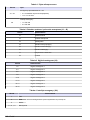
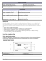
Hach POLYMETRON 8810 ISE Basic User Manual
- Tip
- Basic User Manual

DOC024.98.93054
POLYMETRON Model 8810 pH
Analyzer
09/2016, Edition 9
Basic User Manual
Allgemeines Benutzerhandbuch
Manuale di base per l'utente
Manuel d'utilisation de base
Manual básico del usuario
Podstawowa instrukcja obsługi
Manual de utilizare de bază

English..............................................................................................................................3
Deutsch.......................................................................................................................... 27
Italiano............................................................................................................................ 53
Français......................................................................................................................... 79
Español........................................................................................................................ 104
Polski............................................................................................................................ 130
Română....................................................................................................................... 156
2

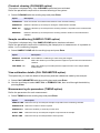
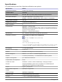
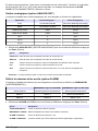
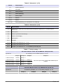
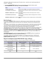
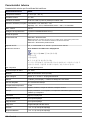
Specifications
Specifications are subject to change without notice.
Specification Details
Ambient temperature 5 - 40 °C (41 - 104 °F)
Relative humidity 10 to 80%
Operating altitude From 0 to 2,000 m. (6,550 ft.) above sea level
Mains power supply 110/220/240 VAC, 50/60 Hz, ± 10%
Fuses: 110 to 120V, T630mAL250V; 220V to 240V, T1.25AL250V
Max. consumption 110 VA
Overvoltage category 2 (according to standard EN 61010-1)
Pollution degree 2
CE compliance EN61326-1: EMC Directive
Note: This is a Class A product. In a domestic environment this product may cause radio
interference in which case the user may be required to take adequate measures.
EN61010-1: LVD Directive
ETL approved ETL, conforming to UL 61010-1 and CSA 22.2 No. 61010-1
Korean certification
User Guidance for EMC Class A Equipment
업무용을 위한 EMC 등급 A 장치에 대한
사용자 지침
사용자안내문
A 급 기기 ( 업무용 방송통신기자재 )
이 기기는 업무용 (A 급 ) 전자파적합기기로서 판매자 또는 사용자는 이 점을 주의
하시기 바라며 , 가정외의 지역에서 사용하는 것을 목적으로 합니다.
Compressed air 4 - 7 bar, filtered and dried
Rinse water pressure 0.5 - 6 bar
Reagents 10 liter storage canister (supplied)
Analog outputs Number: 2; 0 - 20 or 4 - 20 linear programmable
Alarms 2 x Relay (concentration); 1 x Warning or System alarm
Exchangeable sensors pH + reference electrode
Temperature compensation Pt100
Level control Sample; Reagents; Calibration solution; Chemical cleaning
Pumps Peristaltic, micro piston, pulse or volumetric pumps for calibration and conditioning
reagents
Tubing Tygon
®
; Polyethylene
Reagent consumption Application specific
Titration time Application specific
Cycle time Programmable up to 999 minutes
Accuracy < ± 2 to 4% (application specific)
Reproducibility < ± 2 to 4% (application specific)
English 3

Specification Details
Sample lines 1
Sample temperature 0 - 50 °C (32 - 122 °F)
Sample pressure 0.5 - 6 bar
Sample flow rate 40 - 300 liters/hour
Sample volume/cycle 200 - 1000 mL (adjustable)
Panel mount 743 x 482 x 122 mm (H x W x D); < 20 kg
Cabinet (IP 54) 1900 x 600 x 400 mm (H x W x D); < 100 kg
Maximum sound power level ≤ 80 dBA
General information
In no event will the manufacturer be liable for direct, indirect, special, incidental or consequential
damages resulting from any defect or omission in this manual. The manufacturer reserves the right to
make changes in this manual and the products it describes at any time, without notice or obligation.
Revised editions are found on the manufacturer’s website.
Safety information
N O T I C E
The manufacturer is not responsible for any damages due to misapplication or misuse of this product including,
without limitation, direct, incidental and consequential damages, and disclaims such damages to the full extent
permitted under applicable law. The user is solely responsible to identify critical application risks and install
appropriate mechanisms to protect processes during a possible equipment malfunction.
Please read this entire manual before unpacking, setting up or operating this equipment. Pay
attention to all danger and caution statements. Failure to do so could result in serious injury to the
operator or damage to the equipment.
Make sure that the protection provided by this equipment is not impaired. Do not use or install this
equipment in any manner other than that specified in this manual.
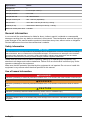
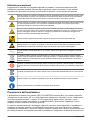
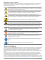
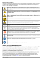
Use of hazard information
D A N G E R
Indicates a potentially or imminently hazardous situation which, if not avoided, will result in death or serious injury.
W A R N I N G
Indicates a potentially or imminently hazardous situation which, if not avoided, could result in death or serious
injury.
C A U T I O N
Indicates a potentially hazardous situation that may result in minor or moderate injury.
N O T I C E
Indicates a situation which, if not avoided, may cause damage to the instrument. Information that requires special
emphasis.
4 English

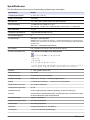
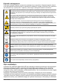
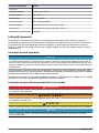
Precautionary labels
Read all labels and tags attached to the product. Personal injury or damage to the product could
occur if not observed. A symbol on the instrument is referenced in the manual with a precautionary
statement.
This symbol, when noted on a product, indicates a potential hazard which could cause serious
personal injury and/or death. The user should reference this instruction manual for operation and/or
safety information.
This symbol, when noted on a product enclosure or barrier, indicates that a risk of electrical shock
and/or electrocution exists and indicates that only individuals qualified to work with hazardous
voltages should open the enclosure or remove the barrier.
This symbol identifies the presence of a strong corrosive or other hazardous substance and a risk of
chemical harm. Only individuals qualified and trained to work with chemicals should handle
chemicals or perform maintenance on chemical delivery systems associated with the equipment.
Products marked with this symbol indicates a risk of finger pinch.
This symbol, when noted on the product, indicates the presence of devices sensitive to electrostatic
discharge and indicates that care must be taken to prevent damage to them.
This symbol, when noted on a product, indicates the instrument is connected to alternate current.
Electrical equipment marked with this symbol may not be disposed of in European domestic or
public disposal systems. Return old or end-of-life equipment to the manufacturer for disposal at no
charge to the user.
Products marked with this symbol indicates that the product contains toxic or hazardous substances
or elements. The number inside the symbol indicates the environmental protection use period in
years.
Products marked with this symbol indicates that the product conforms to relevant South Korean
EMC standards.
This symbol, if noted on the product, indicates the need for protective eye wear.
This symbol indicates the need for protective hand wear
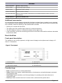
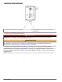
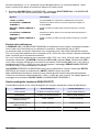
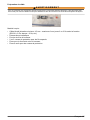
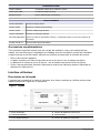
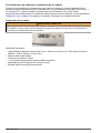
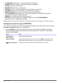
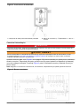
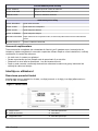
Analyzer overview
The analyzer POLYMETRON Model 8810 ISE is a modular system used for ISE measurements in a
wide range of industrial on–line applications. The analyzer automatically collects on–line samples,
adds the applicable chemicals (such as reagents, buffers, masking agents) and completes the
analysis. The analyzer applies for heavy–duty, industrial on–line environments.
There is a standard panel-mounted version. A wall–mounted polyester cabinet and a free–standing
cabinet to house the analyzer with the necessary reagents are also available. Liquid modules are
installed below the electronic control unit for protection, easy access and service tasks. The hinged
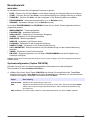
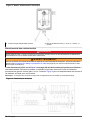
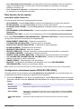
panel tilts forward to access to the rear. Refer to Figure 1 for product overview.
English
5

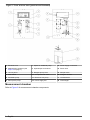
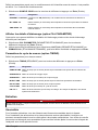
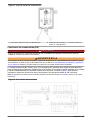
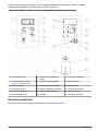
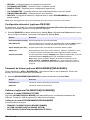
Figure 1 Front and rear view (panel mount illustrated)
1 Electronic unit 7 Space for additional pump 13 Power supply connection
2 Measurement chamber (see
Figure 2 on page 7)
8 Input/Output connections 14 Rinse valve
3 19 inch panel 9 Reagent pump cover 15 Sample valve
4 Main switch 10 Compressed air valve 16 Reagent canister
5 Peristaltic pump 11 Electronic unit (rear) 17 Level detector
6 Micro piston pump 12 Power supply box 18 Tube weight
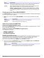
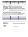
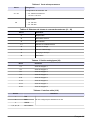
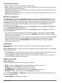
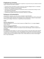
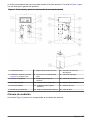
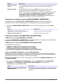
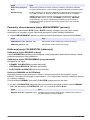
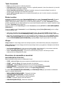
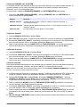
Measurement chamber
Refer to Figure 2 for measurement chamber components.
6
English

Figure 2 Measurement chamber components
1 Stirrer motor 4 Electrode cable 7 Drain tubing
2 Measurement chamber cover 5 Siphon 8 Overflow pipe
3 Electrode 6 Drain valve 9 Threaded fittings
Installation
D A N G E R
Multiple hazards. Only qualified personnel must conduct the tasks described in this section of the document.
Mains power should only be connected once installation has been completed and checked.
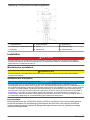
Mechanical installation
C A U T I O N
Multiple hazards. Only qualified personnel must conduct the tasks described in this section of the document.
Mounting the analyzer
N O T I C E
The analyzer should be mounted as near as possible to the sample inlet, and should be located in an easily
accessible area to facilitate periodic checking of the sample flow rate, and for regular maintenance. In an
environmental enclosure that supplies protection from precipitation and direct sunlight, good ventilation and
temperature control if installed outdoors. Wherever the analyzer is to be mounted, it is important to note that it
must be placed in an upright position with the electronic unit (No. 1 in Figure 1 on page 6) at the top. It is
recommended to use a spirit level to ensure that the analyzer is correctly positioned and not leaning to one side
or forward. This is essential to guarantee the accuracy of the analyzer.
Panel mounting
This model is designed as a 19 inch (48.26 cm) rack system. Delivery includes six M6 screws for
mounting the panel onto a rack. All internal connections are factory prepared. Canisters for reagents
can be fitted onto an optional storage tray.
Wall mounting
All internal connections are factory prepared. Cables and tubing are threaded through the cable
glands located on the bottom right side of the cabinet. Canisters for reagents can be fitted onto an
optional storage tray.
English
7

To open the cabinet, push the handle lid upwards, press the lock button, then open the door with a
45° left turn of the handle. To access the cabinet interior, remove the knurled screw on the right side
of the panel and carefully turn the panel sideways to the left taking care not to squeeze any tubing.
Hydraulic connections
D A N G E R
Chemical or biological hazards. If this instrument is used to monitor a treatment process and/or chemical
feed system for which there are regulatory limits and monitoring requirements related to public health,
public safety, food or beverage manufacture or processing, it is the responsibility of the user of this
instrument to know and abide by any applicable regulation and to have sufficient and appropriate
mechanisms in place for compliance with applicable regulations in the event of malfunction of the
instrument.
Sample
The sample enters the analyzer through a 12/14 mm hose (No. 15 in Figure 1 on page 6). Flow rate
should be between 40 and 300 liters/hour under a pressure of 0.5 to 6 bar.
Rinse water
The rinse water enters the analyzer through a 6/8 mm hose (No. 14 in Figure 1 on page 6). Water
pressure must be between 1 and 6 bar.
Reagents
The reagent containers are connected to the pumps according to the instructions corresponding to
the application.
Drain
The analyzed sample is drained at atmospheric pressure through a 12 mm hose (No. 7 in Figure 2
on page 7) delivered with the analyzer for initial startup. Make sure that no backflow occurs in this
tube or the other two drainage tubes (overflow No. 8 in Figure 2 on page 7 and siphon No. 5 in
Figure 2 on page 7).
Note: With the cabinet model, all three tubes drain into a receptacle with a 50 mm outlet.
Compressed air connection
The analyzer requires dry and filtered compressed air at a pressure of 4 to 7 bar. It should be
supplied to the valve (No. 10 in Figure 1 on page 6) using a suitable plastic tube of 4/6 mm diameter.
Electrical installation
D A N G E R
Multiple hazards. Only qualified personnel must conduct the tasks described in this section of the document.
D A N G E R
Electrocution hazard. Always make sure the analyzer is turned off and power is disconnected before making
electrical connections.
D A N G E R
Electrocution hazard. Protective Earth Ground (PE) connection is required.
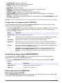
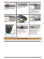
Wiring procedures and cable preparation
The following procedure must be followed for all cables connecting peripherals (e.g. pumps, level
detectors, alarms, etc.) with the electronic unit (No. 11 in Figure 1 on page 6). Some cables will be
supplied ready for use. Other cables which are supplied locally by the user must be prepared
according to the procedure explained in Cable preparation on page 9 before connecting to the
electronic unit.
8
English

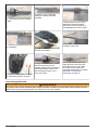
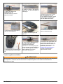
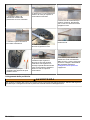
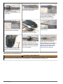
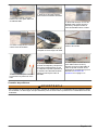
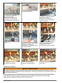
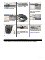
Cable preparation
W A R N I N G
To conform with security standards and to respect the EMC compliancy of the analyzer, this procedure must be
followed for all user supplied cables before connecting them to the electronic unit of the analyzer.
Materials required:
• Shielded cable (diameter minimum 4.5 mm - maximum 6 mm) with 2 or 3 wires depending on
function (RS232 = 3 wires, Alarm = 2 wires, etc.)
• Metal cable gland
• Grounding ferrule
• 2 or 3 protective plugs for the exposed wires
• Clamp for the grounding ferrule
• Crimping pliers for the protective plugs
English 9

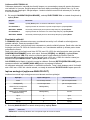
1. Place the nut and metal seal of
the cable gland onto the shielded
cable.
2. Remove 8 cm of the outer
cabling to reveal the braided
shielding.
3. Remove all but 12 mm of the
shielding to reveal the interior
wires, then roll the remainder of
the shielding back over the cable.
4. Insert the grounding ferrule over
the shielding.
5. Use the clamp to fix the ferrule
securely to the cable.
6. Remove 5 mm of the external
insulation of the wires.
7. Use the crimping pliers to attach
the protective plugs to the wires.
8. Bring the metal shield up over
the ferrule and lock the two
together making sure the ferrule is
not exposed at the cable end of
the shield. Bring up the nut to
cover the shield.
9. Pass the threaded part of the
cable gland over the wires and
screw into the nut on the cable.
The cable is now ready to be
connected following the procedure
described in Connecting
peripherals on page 10.
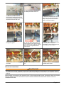
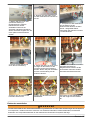
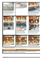
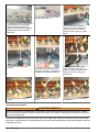
Connecting peripherals
W A R N I N G
To conform with security standards and to respect the EMC compliancy of the analyzer, this procedure must be
followed for connecting all peripherals to the electronic unit of the analyzer.
10 English

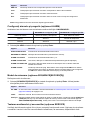
1. Select an unused opening
nearest to the cable connection on
the electronic board. Remove the
screw and nut combination and set
aside the screw for later use.
2. Take the cable, unscrew the
threaded part and remove it.
3. Screw the threaded part into the
electronic unit opening selected in
step 1 using the nut removed in
step 1 to secure in place.
4. Pass the rest of the cable
through the gland.
5. Pull the cable slightly with one
hand until the inner shield comes
into contact with the gland. Tighten
the nut onto the gland with the
other hand.
6. Tighten the nut with a wrench to
secure in place. It may be
necessary to use a second wrench
to hold the top nut in place.
7. Connect the wires to the correct
terminals.
8. Secure the wires with a cable
tie.
9. Cut the cable tie as near as
possible to the wires.
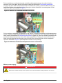
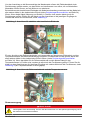
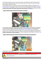
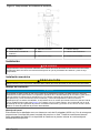
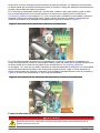
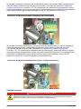
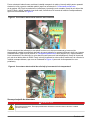
Electrode connections
W A R N I N G
To conform with security standards and to respect the EMC compliancy of the analyzer, this procedure must be
followed when connecting selective, reference, combined and temperature electrodes to the electronic unit of the
analyzer.
Before being connected to the terminal block of the measurement board, electrode cables must pass
through ferrite blocks to minimize the risk of outside interferences that could cause erroneous
measurement data.
English
11

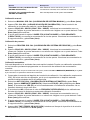
For the selective or combined electrode, install the cable gland and pass the cable of into the
electronic unit in the same way as for all other cables (as described in Connecting peripherals
on page 10). Once both wires (measurement and shield) are in place, pass them both through the
ferrite block. Make a loop by passing them through a second time before connecting them to their
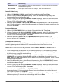
respective inputs as illustrated in Figure 3.
Figure 3 Selective or combined electrode connection
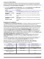
For the reference electrode (not applicable in the case of a combined electrode) and the temperature
sensor, install the cable glands and pass the cables into the electronic unit in the same way as for all
other cables (as described in Connecting peripherals on page 10). Once the reference electrode wire
and the two temperature sensor wires are in place, pass them all through the second ferrite block.
Make a loop by passing them through a second time before connecting them to their respective
inputs as illustrated in Figure 4 (the temperature sensor has no polarity).
Figure 4 Reference electrode and temperature sensor connections
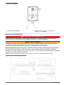
Mains power supply
D A N G E R
Electrocution hazard. Always remove power to the instrument before making electrical connections.
12 English

D A N G E R
Electrocution hazard. Protective Earth Ground (PE) connection is required.
D A N G E R
Electrical shock and fire hazards. Make sure to identify the local disconnect clearly for the conduit
installation.
W A R N I N G
Potential Electrocution Hazard. If this equipment is used outdoors or in potentially wet locations, a
Ground Fault Interrupt device must be used for connecting the equipment to its mains power source.
C A U T I O N
Multiple hazards. Only qualified personnel must conduct the tasks described in this section of the
document.
N O T I C E
Install the device in a location and position that gives easy access to the disconnect device and its operation.
N O T I C E
The analyzer is factory configured to either 110/120 VAC or 220/240 VAC. Make sure to connect the correct
power supply to the analyzer.
Connect equipment in accordance with local, state or national electrical codes. Obey all codes and
regulations for wiring. Install cables into the instrument enclosure through the supplied cable glands.
Use screened and screen earthed cable for the mains connection. The mains wire specifications are:
diameter between 7 and 9.5 mm, 3 cores, 10 Amps minimum current rating, between 1 mm
2
(AWG18) and 2.5 mm
2
(AWG14) minimum CSA (Cross Sectional Area). For all other signal
connections use screened instrument cable. Use also screen earthed cable for the signal
connections.
Note: Equipment intended for permanent connection to the MAINS must have provision for connection of a wiring
system in accordance with ANSI/NFPA 70, NEC, with CSA C22.1
Make sure that a 2 pole circuit breaker with a minimum breaking capcity of 20 A is installed in the
power line. Install a local disconnect for the instrument within 3 m (10 ft) of the instrument. Put a label
on the disconnect that identifies it as the main disconnect device for the instrument.
When the wiring of the system is completed, do the steps that follow to energize the system:
1. Open the power supply box (No. 12 in Figure 1 on page 6).
2. Pass the power cable through the cable gland and connect the earth, neutral and live wires to
terminals 1, 2 and 3 respectively as indicated in Figure 5.
English
13

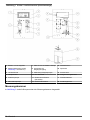
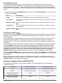
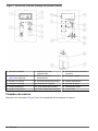
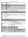
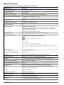
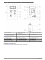
Figure 5 Power supply box
1 Mains power cable gland 2 Connection terminals (1 = Earth, 2 = Neutral, 3 =
Live)
Input/Output connections
D A N G E R
Electrocution hazard. Always make sure the analyzer is turned off and power is disconnected before making any
of the connections in this section.
W A R N I N G
To conform with security standards and to respect the EMC compliancy of the analyzer, follow the procedures
defined in Wiring procedures and cable preparation on page 8 for all connections to the electronic unit of the
analyzer.
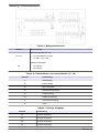
The electronic unit (No. 11 in Figure 1 on page 6) must be opened from the rear to make these
connections. Unscrew the four screws holding the unit rear panel and gently swing open from left to
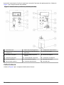
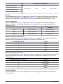
right. Refer to Figure 6 for terminal locations and the following tables for the functions.
Note: The terminal connectors diagram is also physically located on the rear of the electronic unit.
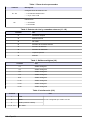
Figure 6 Terminal connectors
14 English

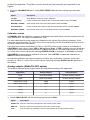
Table 1 Microprocessor board
Terminal Description
X1 - X4
Relay configurations K5 - K8
• 2-3: Dry contact relay
• 1-2 and 3-4: 24 VDC
X5
Serial interface
• 1-2: RS 232
• 2-3: RS 485
Table 2 Level detector and external commands (J1 - J8)
Terminal Use
J1 Start / Standby
J2 External sample
J3 Not used
J4 Conditioning solution
J5 Titration solution
J6 Calibration solution
J7 Chemical cleaning
J8 Sample
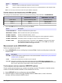
Table 3 Analog outputs (J9)
Terminal Use
1-2 Analog output 1
3-4 Analog output 2
5-6 Analog output 3
7-8 Analog output 4
9-10 Analog output 5
11-12 Analog output 6
13-14 Analog output 7
15-16 Analog output 8
Table 4 Serial interface (J10)
Terminal Use
1 TXD
RS 232 user configured with X5 2 RXD
3 GND
4, 5, 6, 7, 8 Not used
English 15

Table 5 Accessories 1 (J13)
Terminal Use
1-11 Heating system
2-3 Mixer
4-5 Rinse valve
6-7 Flush valve
8-9 Sample valve
12-13 Alarm 2
14-15 Alarm 1
16-17-18 System alarm (16-17 for NO or 16-18 for NC)
Table 6 Accessories 2 (J14)
Terminal Use
1-11 (8-10) Automatic calibration or external sample pump (connect 8 and 10 and set jumper X4 at 2-3)
2-3 Not used
4-5 Chemical cleaning valve
6-7 Dilution valve
8-9 Not used
10-11 Pump 4
12-13 Pump 3 (X3 set at 1-2 and 3-4)
14-15 Pump 2 (X2 set at 1-2 and 3-4)
16-17 Pump 1 (X1 set at 1-2 and 3-4) / Automatic calibration
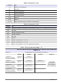
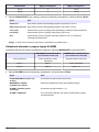
Table 7 Pump functions 1 - 4
CAL AUTO YES or MANUAL YES
Jumper X4 X4 set at 2-3 and a strap between 8 and 10 of J14
Pump 1 Pump 2 Pump 3 Pump 4
1 titrant / 1 cond. Titrant 1 Cond 1
CAL AUTO or OTHER SAMPLE
1 titrant / 2 cond. Titrant 1 Cond 1 Cond 2
2 titrants / 1 cond. Titrant 1 Cond 1 Titrant 2
2 titrants / 2 cond. Titrant 1 Cond 1 Titrant 2
CAL AUTO NO and MANUAL NO
Jumper X4 X4 set between 1-2 and 3-4 and no strap between 8 and 10 of J14
Pump 1 Pump 2 Pump 3 Pump 4
16 English

CAL AUTO NO and MANUAL NO
1 titrant / 1 cond.
Titrant 1 Cond 1 Cond 2 Titrant 2
1 titrant / 2 cond.
2 titrants / 1 cond.
2 titrants / 2 cond.
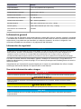
Alarms
Refer also to Figure 6 on page 14 and Table 5 on page 16. Alarm threshold relays (K2 and K3) are
set to normally open (NO). The system alarm relay (K1) can be set to normally open (terminals
16 and 17) or normally closed (terminals 16 and 18).
Analog outputs
Refer also to Figure 6 on page 14 and Table 3 on page 15. The analog outputs 0-20 mA or 4-20 mA
are galvanically insulated. The following table shows the allocation of the different outputs:
Analyzer
I out 1 Terminal 1-2 of J9 Measurement channel
I out 2 Terminal 3-4 of J9 Measurement potential
I out 3 Terminal 5-6 of J9 Not used
Sample level detector
Refer also to Figure 6 on page 14 and Table 2 on page 15. The reactor is equipped with a sample
level detector. Wire the connection to J8 as follows:
J8 Terminal number Color
1 Brown
2 Green
3 Yellow
4 White
Reagent level detector
Refer also to Figure 6 on page 14 and Table 2 on page 15. Each reagent canister is equipped with a
level detector. For each reagent, wire the connections to J4, J5, J6 and J7 as follows:
J4, J5, J6 and J7 Terminal number Color
1 Not used
2 Not used
3 Brown
4 White
RS232 connection
Refer also to Figure 6 on page 14 and Table 4 on page 15. Wire the connection to J10 as follows:
J10 Terminal number DB9 Plug DB25 Plug
1 (TXD) RXD: 2 RXD: 2
2 (RXD TXD: 3 TXD: 3
3 (GND) COM: 5 COM: 7
English 17

The 8810 configuration is:
• Speed: 9600 baud
• Data: 8 bits
• Stop bit: 2
• Parity: none
On startup the analyzer sends the name and software version:
• ANALYZER 8810 : 00 : 00 : 00 :
• pH X.XX : 00 : 00 : 00 :
In measurement mode, the analyzer sends the following data:
• Titration HH : MM : SS
• M1 XXXXEXX XX.X°C XXX for the first final point
• M2 XXXXEXX XX.X°C XXX for the second final point
• M3 XXXXEXX XX.X°C XXX for the differential between the two final points
Where:
• MX XXXXEXX = concentration measurement value
• XX.X°C = temperature
• XXX = value of the potential
In graph plotting mode, the analyzer sends the following data:
• Plotting HH : MM : SS
• P : XX.X°C XXX
Where:
• XX.X°C = temperature
• XXX = pH value
Where appropriate, the analyzer also sends the following messages with a time stamp (HH : MM :
SS):
ACTIONS
Cleaning Chemical cleaning
Stopped Analyzer stopped
Fix-time Time between two cycles
Standby Analyzer in standby
AUTO SYS CAL Automatic calibration
PROCESS SYS CAL Process calibration
MANUAL SYS CAL Manual calibration
SYSTEM ERRORS
LEVEL SAMPLE Sample missing from measuring cell
OVER TITR TIME Titration time is too long
ERROR CALIB Automatic calibration error
18 English

WARNINGS
LEVEL REAGENT Titration reagent missing
LEVEL COND Conditioning reagent missing
LEVEL CALIB Calibration solution missing
LEVEL CLEANING Cleaning solution missing
RETURN PROCESS After an external sample measurement, this message indicates a return to process
measurement
SLOPE CALIB 1/2 Automatic calibration error
Additional accessories
Any accessories that have been purchased but that have not been factory installed, can be installed
now. Instructions for the installation and wiring are given in the full user manual.Once everything has
been installed, check the following in the measurement chamber:
• Nothing is in contact with the stirrer
• The upper part of the overflow pipe is about 2 cm above the siphon
• The level detector is about 1 cm below the bottom of the siphon inlet
• If not connected, connect the measuring electrode to the thicker cable and the reference electrode
to the thinner cable.
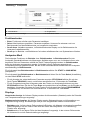
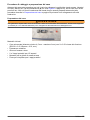
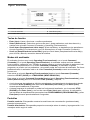
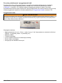
User interface
Front panel description
The interface is via a 4-key keyboard, a 4-digit numeric display and an alphanumeric display of 2-
lines of 16 characters.
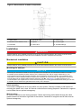
Figure 7 Front panel
1 Numeric display 4 Scroll up key
2 Select key 5 Enter key
3 Alphanumeric display 6 Scroll down key
Function keys
• Enter: Invoke functions or confirm parameters.
• Select: Select menu options, adjust parameters, exit submenus, and switch between command
and operating mode.
• Scroll down: Adjust variables, scroll through displays in operating mode and submenus in
command mode.
• Scroll up: Same as scroll down but in reverse order, and cancel the system alarm.
English
19

Analyzer modes
The analyzer functions in Operating mode or Command mode. In Operating mode the analyzer
performs standard actions such as measurement, calibration, etc. A limited number of parameters
can also be displayed using the scroll keys. In Command mode the analyzer can be programmed,
parameters displayed and analyzer functions tested. By default, the analyzer is in Command mode
when first switched on.
To enter Operating mode from Command mode, select START from the MAIN MENU.
To enter Command mode from Operating mode, press Select to display the STOP command, then
• if you only wish to display currently defined parameters, from the STOP command use the scroll
keys to select READING and press Enter for approximately 3 seconds.
• if you wish to program the analyzer or test analyzer functions, from the STOP command press
Enter and then Enter again to confirm. Then use the scroll keys to select PROGRAMMING and
press Enter for approximately 3 seconds.
Displays
Numeric display: This display shows concentration (default), potential or temperature
measurements.
Alphanumeric display: This display provides messages on status and programming. Messages are
different according to the mode:
• Operating mode: The top line indicates units, measurement type and any activated alarms. The
bottom line indicates the analyzer status, e.g. calibration, titration, etc.
• Command mode: The top line indicates the main menu. The bottom line indicates submenus and
data settings.
Menu overview
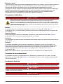
MAIN MENU
The main menu gives access to the following functions:
• STOP - Pressing Enter causes the measurement process to stop immediately
• START - Pressing Enter initiates the measurement process
• STAND-BY - Pressing Enter puts the analyzer in standby
• PROGRAMMING - Program the analyzer (Command mode only)
• READING - View parameters (Operating mode only)
In PROGRAMMING or READING mode the following options can be selected using the scroll keys:
• MEASUREMENT - Titration parameters
• CALIBRATION - Calibrate the analyzer
• ANALOG-OUT - Analog output parameters
• ALARM - Alarm limit parameters
• SEQUENCE - Measurement mode
• SERVICE - Check the analyzer and accessory operations
• CLEANING - Chemical cleaning parameters
• SAMPLE COND. - Sample conditioning parameters
• CAL PARAMETER - View the primary and last calibration details
• TIMING - Titration cycle parameters
• PM XXXX - System configuration (only available in PROGRAMMING mode and requires a valid
password)
Note: Some of the above options are only available if the relevant accessory has been installed.
20
English
Pagina se încarcă...
Pagina se încarcă...
Pagina se încarcă...
Pagina se încarcă...
Pagina se încarcă...
Pagina se încarcă...
Pagina se încarcă...
Pagina se încarcă...
Pagina se încarcă...
Pagina se încarcă...
Pagina se încarcă...
Pagina se încarcă...
Pagina se încarcă...
Pagina se încarcă...
Pagina se încarcă...
Pagina se încarcă...
Pagina se încarcă...
Pagina se încarcă...
Pagina se încarcă...
Pagina se încarcă...
Pagina se încarcă...
Pagina se încarcă...
Pagina se încarcă...
Pagina se încarcă...
Pagina se încarcă...
Pagina se încarcă...
Pagina se încarcă...
Pagina se încarcă...
Pagina se încarcă...
Pagina se încarcă...
Pagina se încarcă...
Pagina se încarcă...
Pagina se încarcă...
Pagina se încarcă...
Pagina se încarcă...
Pagina se încarcă...
Pagina se încarcă...
Pagina se încarcă...
Pagina se încarcă...
Pagina se încarcă...
Pagina se încarcă...
Pagina se încarcă...
Pagina se încarcă...
Pagina se încarcă...
Pagina se încarcă...
Pagina se încarcă...
Pagina se încarcă...
Pagina se încarcă...
Pagina se încarcă...
Pagina se încarcă...
Pagina se încarcă...
Pagina se încarcă...
Pagina se încarcă...
Pagina se încarcă...
Pagina se încarcă...
Pagina se încarcă...
Pagina se încarcă...
Pagina se încarcă...
Pagina se încarcă...
Pagina se încarcă...
Pagina se încarcă...
Pagina se încarcă...
Pagina se încarcă...
Pagina se încarcă...
Pagina se încarcă...
Pagina se încarcă...
Pagina se încarcă...
Pagina se încarcă...
Pagina se încarcă...
Pagina se încarcă...
Pagina se încarcă...
Pagina se încarcă...
Pagina se încarcă...
Pagina se încarcă...
Pagina se încarcă...
Pagina se încarcă...
Pagina se încarcă...
Pagina se încarcă...
Pagina se încarcă...
Pagina se încarcă...
Pagina se încarcă...
Pagina se încarcă...
Pagina se încarcă...
Pagina se încarcă...
Pagina se încarcă...
Pagina se încarcă...
Pagina se încarcă...
Pagina se încarcă...
Pagina se încarcă...
Pagina se încarcă...
Pagina se încarcă...
Pagina se încarcă...
Pagina se încarcă...
Pagina se încarcă...
Pagina se încarcă...
Pagina se încarcă...
Pagina se încarcă...
Pagina se încarcă...
Pagina se încarcă...
Pagina se încarcă...
Pagina se încarcă...
Pagina se încarcă...
Pagina se încarcă...
Pagina se încarcă...
Pagina se încarcă...
Pagina se încarcă...
Pagina se încarcă...
Pagina se încarcă...
Pagina se încarcă...
Pagina se încarcă...
Pagina se încarcă...
Pagina se încarcă...
Pagina se încarcă...
Pagina se încarcă...
Pagina se încarcă...
Pagina se încarcă...
Pagina se încarcă...
Pagina se încarcă...
Pagina se încarcă...
Pagina se încarcă...
Pagina se încarcă...
Pagina se încarcă...
Pagina se încarcă...
Pagina se încarcă...
Pagina se încarcă...
Pagina se încarcă...
Pagina se încarcă...
Pagina se încarcă...
Pagina se încarcă...
Pagina se încarcă...
Pagina se încarcă...
Pagina se încarcă...
Pagina se încarcă...
Pagina se încarcă...
Pagina se încarcă...
Pagina se încarcă...
Pagina se încarcă...
Pagina se încarcă...
Pagina se încarcă...
Pagina se încarcă...
Pagina se încarcă...
Pagina se încarcă...
Pagina se încarcă...
Pagina se încarcă...
Pagina se încarcă...
Pagina se încarcă...
Pagina se încarcă...
Pagina se încarcă...
Pagina se încarcă...
Pagina se încarcă...
Pagina se încarcă...
Pagina se încarcă...
Pagina se încarcă...
Pagina se încarcă...
Pagina se încarcă...
Pagina se încarcă...
Pagina se încarcă...
Pagina se încarcă...
Pagina se încarcă...
Pagina se încarcă...
Pagina se încarcă...
Pagina se încarcă...
-
 1
1
-
 2
2
-
 3
3
-
 4
4
-
 5
5
-
 6
6
-
 7
7
-
 8
8
-
 9
9
-
 10
10
-
 11
11
-
 12
12
-
 13
13
-
 14
14
-
 15
15
-
 16
16
-
 17
17
-
 18
18
-
 19
19
-
 20
20
-
 21
21
-
 22
22
-
 23
23
-
 24
24
-
 25
25
-
 26
26
-
 27
27
-
 28
28
-
 29
29
-
 30
30
-
 31
31
-
 32
32
-
 33
33
-
 34
34
-
 35
35
-
 36
36
-
 37
37
-
 38
38
-
 39
39
-
 40
40
-
 41
41
-
 42
42
-
 43
43
-
 44
44
-
 45
45
-
 46
46
-
 47
47
-
 48
48
-
 49
49
-
 50
50
-
 51
51
-
 52
52
-
 53
53
-
 54
54
-
 55
55
-
 56
56
-
 57
57
-
 58
58
-
 59
59
-
 60
60
-
 61
61
-
 62
62
-
 63
63
-
 64
64
-
 65
65
-
 66
66
-
 67
67
-
 68
68
-
 69
69
-
 70
70
-
 71
71
-
 72
72
-
 73
73
-
 74
74
-
 75
75
-
 76
76
-
 77
77
-
 78
78
-
 79
79
-
 80
80
-
 81
81
-
 82
82
-
 83
83
-
 84
84
-
 85
85
-
 86
86
-
 87
87
-
 88
88
-
 89
89
-
 90
90
-
 91
91
-
 92
92
-
 93
93
-
 94
94
-
 95
95
-
 96
96
-
 97
97
-
 98
98
-
 99
99
-
 100
100
-
 101
101
-
 102
102
-
 103
103
-
 104
104
-
 105
105
-
 106
106
-
 107
107
-
 108
108
-
 109
109
-
 110
110
-
 111
111
-
 112
112
-
 113
113
-
 114
114
-
 115
115
-
 116
116
-
 117
117
-
 118
118
-
 119
119
-
 120
120
-
 121
121
-
 122
122
-
 123
123
-
 124
124
-
 125
125
-
 126
126
-
 127
127
-
 128
128
-
 129
129
-
 130
130
-
 131
131
-
 132
132
-
 133
133
-
 134
134
-
 135
135
-
 136
136
-
 137
137
-
 138
138
-
 139
139
-
 140
140
-
 141
141
-
 142
142
-
 143
143
-
 144
144
-
 145
145
-
 146
146
-
 147
147
-
 148
148
-
 149
149
-
 150
150
-
 151
151
-
 152
152
-
 153
153
-
 154
154
-
 155
155
-
 156
156
-
 157
157
-
 158
158
-
 159
159
-
 160
160
-
 161
161
-
 162
162
-
 163
163
-
 164
164
-
 165
165
-
 166
166
-
 167
167
-
 168
168
-
 169
169
-
 170
170
-
 171
171
-
 172
172
-
 173
173
-
 174
174
-
 175
175
-
 176
176
-
 177
177
-
 178
178
-
 179
179
-
 180
180
-
 181
181
-
 182
182


Hach POLYMETRON 8810 ISE Basic User Manual
- Tip
- Basic User Manual
în alte limbi
- français: Hach POLYMETRON 8810 ISE
- English: Hach POLYMETRON 8810 ISE
- polski: Hach POLYMETRON 8810 ISE
- Deutsch: Hach POLYMETRON 8810 ISE
- italiano: Hach POLYMETRON 8810 ISE
- español: Hach POLYMETRON 8810 ISE
Lucrări înrudite
-
 Hach POLYMETRON 8810 ORP Basic User Manual
-
 Hach POLYMETRON 8810 ISE Basic User Manual
-
 Hach Polymetron 9610sc SiO2 Ghid de instalare
-
 Hach Lange ORBISPHERE 3100 Basic User Manual
-
 Hach pHD Sensor Manual de utilizare
-
 Hach Lange ORBISPHERE 3100 Basic User Manual
-
 Hach ORBISPHERE K-M1100 Basic User Manual
-
 Hach Polymetron 9610sc Maintenance And Troubleshooting Manual
-
 Hach ORBISPHERE 410 Basic User Manual
-
 Hach Polymetron 9611sc PO43-LR Instrucțiuni de utilizare


Alte documente
-
Leuchten Direkt 14840-55 Manual de utilizare
-
Dräger Pac 7000 Instructions For Use Manual
-
HQ EL-GD10 Specificație
-
Weller WTHA 1 Supplementary Operating Instructions
-
Paul Neuhaus 8111 Manual de utilizare
-
Duravit 252559 Mounting Instruction
-
Duravit 631001 Mounting Instruction
-
CHAUVIN ARNOUX CA 8345 Ghid de inițiere rapidă
-
HellermannTyton Reliseal V 56 Installation Instructions Manual
-
Festool SYS-PST 1500 Li HP Instrucțiuni de utilizare