Hach Polymetron 9610sc SiO2 Ghid de instalare
- Tip
- Ghid de instalare

DOC023.98.80246
Polymetron 9610sc SiO
2
07/2016, Edition 2
Installation
Installation
Installazione
Installation
Instalación
Instalação
Instalace
Installation
Installatie
Instalacja
Installation
Asentaminen
Инсталиране
Telepítés
Instalarea
Montavimas
Установка
Kurulum
Inštalácia
Namestitev
Ugradnja
Εγκατάσταση
Paigaldamine

English..............................................................................................................................3
Deutsch.......................................................................................................................... 23
Italiano............................................................................................................................ 44
Français......................................................................................................................... 65
Español.......................................................................................................................... 86
Português.................................................................................................................... 107
Čeština......................................................................................................................... 128
Dansk............................................................................................................................149
Nederlands................................................................................................................. 169
Polski............................................................................................................................ 189
Svenska....................................................................................................................... 210
Suomi............................................................................................................................230
български................................................................................................................... 250
Magyar......................................................................................................................... 271
Română....................................................................................................................... 291
lietuvių kalba...............................................................................................................312
Русский........................................................................................................................333
Türkçe...........................................................................................................................355
Slovenský jazyk......................................................................................................... 375
Slovenski..................................................................................................................... 395
Hrvatski........................................................................................................................ 415
Ελληνικά...................................................................................................................... 435
eesti keel..................................................................................................................... 456
2

Table of contents
Safety information on page 3 Wiring connections overview on page 13
Product overview on page 4 Connect optional devices on page 16
Mechanical installation on page 6 Preparation for use on page 17
Plumbing on page 6 Specifications on page 20
Electrical installation on page 11
General information
In no event will the manufacturer be liable for direct, indirect, special, incidental or consequential
damages resulting from any defect or omission in this manual. The manufacturer reserves the right to
make changes in this manual and the products it describes at any time, without notice or obligation.
Revised editions are found on the manufacturer’s website.
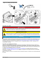
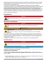
Safety information
N O T I C E
The manufacturer is not responsible for any damages due to misapplication or misuse of this product including,
without limitation, direct, incidental and consequential damages, and disclaims such damages to the full extent
permitted under applicable law. The user is solely responsible to identify critical application risks and install
appropriate mechanisms to protect processes during a possible equipment malfunction.
Please read this entire manual before unpacking, setting up or operating this equipment. Pay
attention to all danger and caution statements. Failure to do so could result in serious injury to the
operator or damage to the equipment.
Make sure that the protection provided by this equipment is not impaired. Do not use or install this
equipment in any manner other than that specified in this manual.
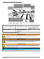
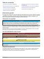
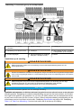
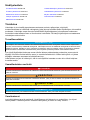
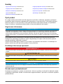
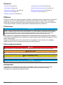
Use of hazard information
D A N G E R
Indicates a potentially or imminently hazardous situation which, if not avoided, will result in death or serious injury.
W A R N I N G
Indicates a potentially or imminently hazardous situation which, if not avoided, could result in death or serious
injury.
C A U T I O N
Indicates a potentially hazardous situation that may result in minor or moderate injury.
N O T I C E
Indicates a situation which, if not avoided, may cause damage to the instrument. Information that requires special
emphasis.
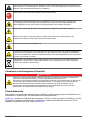
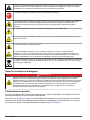
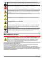
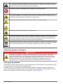
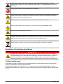
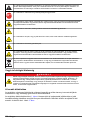
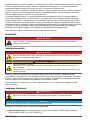
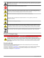
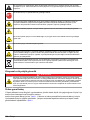
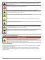
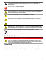
Precautionary labels
Read all labels and tags attached to the instrument. Personal injury or damage to the instrument
could occur if not observed. A symbol on the instrument is referenced in the manual with a
precautionary statement.
English
3

This is the safety alert symbol. Obey all safety messages that follow this symbol to avoid potential
injury. If on the instrument, refer to the instruction manual for operation or safety information.
This symbol indicates the need for protective eye wear.
This symbol identifies a risk of chemical harm and indicates that only individuals qualified and trained
to work with chemicals should handle chemicals or perform maintenance on chemical delivery
systems associated with the equipment.
This symbol indicates that a risk of electrical shock and/or electrocution exists.
This symbol indicates that the marked item can be hot and should not be touched without care.
This symbol indicates that a risk of fire is present.
This symbol identifies the presence of a strong corrosive or other hazardous substance and a risk of
chemical harm. Only individuals qualified and trained to work with chemicals should handle chemicals
or perform maintenance on chemical delivery systems associated with the equipment.
Electrical equipment marked with this symbol may not be disposed of in European domestic or public
disposal systems. Return old or end-of-life equipment to the manufacturer for disposal at no charge to
the user.
Chemical and biological safety
D A N G E R
Chemical or biological hazards. If this instrument is used to monitor a treatment process and/or
chemical feed system for which there are regulatory limits and monitoring requirements related to
public health, public safety, food or beverage manufacture or processing, it is the responsibility of the
user of this instrument to know and abide by any applicable regulation and to have sufficient and
appropriate mechanisms in place for compliance with applicable regulations in the event of malfunction
of the instrument.
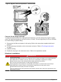
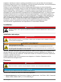
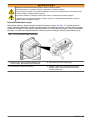
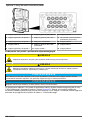
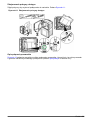
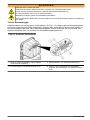
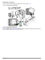
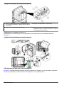
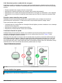
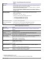
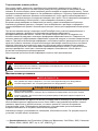
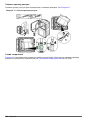
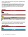
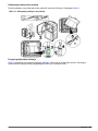
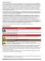
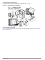
Product overview
The analyzer uses the heteropoly blue chemistry to measure low concentrations of silica for high-
purity steam cycle applications.
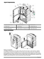
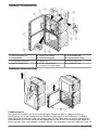
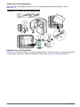
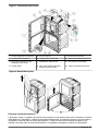
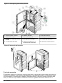
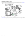
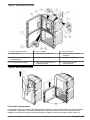
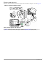
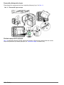
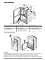
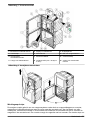
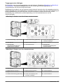
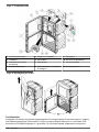
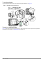
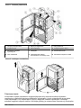
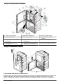
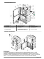
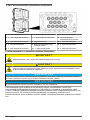
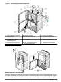
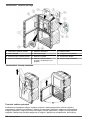
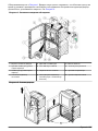
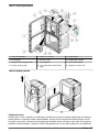
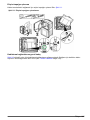
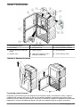
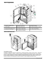
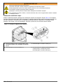
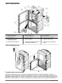
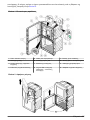
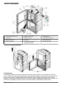
Refer to Figure 1 for the analyzer overview. The doors can be easily removed for better access
during installation and maintenance procedures. The doors must be installed and closed during
operation. Refer to Figure 2.
4
English

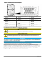
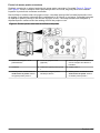
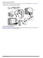
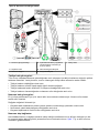
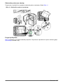
Figure 1 Product overview
1 Upper and lower doors 5 Display and keypad 9 Analytics panel
2 Funnel cover 6 SD card slot 10 Reagent bottle tray
3 Grab sample input funnel 7 Power switch 11 Colorimeter cover
4 Status indicator light 8 Power LED (on = analyzer is on) 12 Grab sample valve
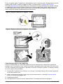
Figure 2 Door removal
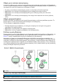
Theory of operation
The analyzer uses a pressurized reagent system and solenoid valves to supply sample, reagents
and calibration solutions to the sample cell. At the start of each measurement cycle, sample flows
into the sample cell. When the sample cell is full, reagents flow into the sample cell. A stirrer mixes
the reagents with the sample. The stirrer stops to let the mixture become stable and to let air bubbles
dissipate. The analyzer measures the color of the sample. When the measurement is complete, new
sample flushes the sample cell, and the measurement cycle starts again.
English
5

During a calibration cycle, the calibration solution flows into the sample cell. The analyzer adds the
reagents, measures the color of the calibration solution and calculates the slope of the calibration
curve. The analyzer uses the slope to calculate the concentration of samples.
In the heteropoly blue method
1
, an acidic molybdate reagent reacts with silica and phosphate to form
molybdosilicic and molybdophosphoric acids. A citric acid/surfactant reagent removes the
phosphomolybdic acid complexes. The surfactant prevents the formation of air bubbles on the
sample cell walls. The analyzer uses the absorbance of this solution as the zero reference, which
corrects for interference from background turbidity or color, changes in lamp intensity or optical
changes of the sample cell. An amino acid reagent reduces the molybdosilicic acid to a blue color.
The analyzer measures the intensity of the blue color and calculates the silica concentration.
More information is available on the manufacturer's website.
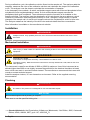
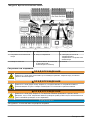
Installation
D A N G E R
Multiple hazards. Only qualified personnel must conduct the tasks described in this section of the
document.
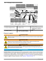
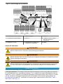
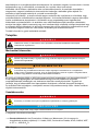
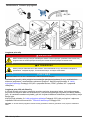
Mechanical installation
D A N G E R
Risk of injury or death. Make sure that the wall mounting is able to hold 4 times the weight of the
equipment.
W A R N I N G
Personal injury hazard.
Instruments or components are heavy. Use assistance to install or move.
The object is heavy. Make sure that the instrument is securely attached to a wall, table or floor for a
safe operation.
This instrument is rated for an altitude of 2000 m (6562 ft) maximum. Use of this instrument at an
altitude higher than 2000 m can slightly increase the potential for the electrical insulation to break
down, which can result in an electric shock hazard. The manufacturer recommends that users with
concerns contact technical support.
Install the analyzer indoors, in a non-hazardous environment. Refer to the supplied mounting
documentation.
Plumbing
D A N G E R
Fire hazard. This product is not designed for use with flammable liquids.
N O T I C E
Do not install reagents until all plumbing is complete.
Make sure to use the specified tubing size.
1
Standard Methods for the Examination of Water and Wastewater, 21st Edition, 2005, Centennial
Edition, APHA, AWWA, WEF, pp 4–167, 4500-SiO
2
D.
6 English

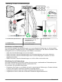
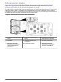
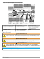
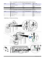
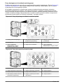
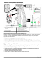
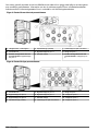
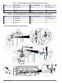
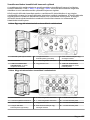
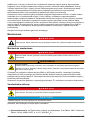
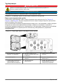
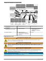
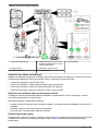
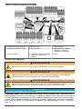
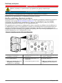
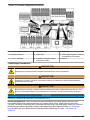
Plumbing access ports
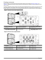
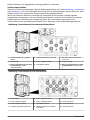
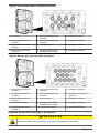
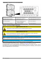
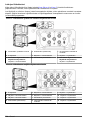
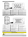
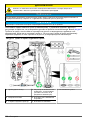
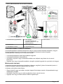
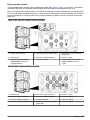
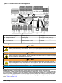
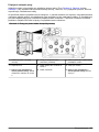
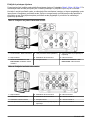
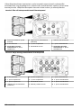
Make plumbing connections through the plumbing access ports. Refer to Figure 3, Figure 4 or
Figure 5. To keep the enclosure rating, make sure that plugs are installed in the plumbing ports that
are not used.
If using an external air purge, refer to the instructions supplied with the air purge kit to remove the fan
filter and replace it with a plug. Refer to the operations manual for instructions on enabling the air
purge. Refer to the maintenance and troubleshooting manual for the part number for the air purge kit.
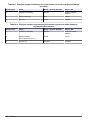
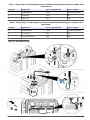
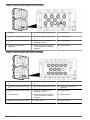
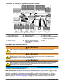
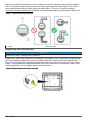
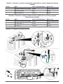
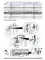
Figure 3 Ports for one or two sample streams
1 Drain vent-keep open 4 Air purge inlet (optional) 7 Case drain for spills or leaks
2 Not used 5 Sample 1 bypass drain 8 Sample 1 inlet
3 Two sample stream analyzers
only: Sample 2 bypass drain
6 Chemical drain 9 Two sample stream analyzers
only: Sample 2 inlet
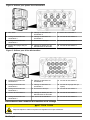
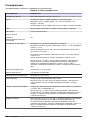
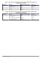
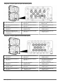
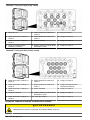
Figure 4 Ports for four sample streams
1 Not used 5 Sample 2 bypass drain 9 Sample 1 inlet
2 Sample 4 bypass drain 6 Sample 1 bypass drain 10 Sample 2 inlet
3 Sample 3 bypass drain 7 Chemical drain 11 Sample 3 inlet
4 Air purge inlet (optional) 8 Case drain for spills or leaks 12 Sample 4 inlet
English 7

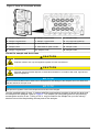
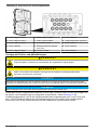
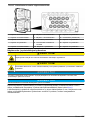
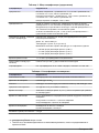
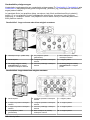
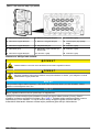
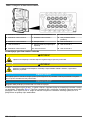
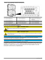
Figure 5 Ports for six sample streams
1 Sample 6 bypass drain 6 Sample 2 bypass drain 11 Sample 2 inlet
2 Sample 5 bypass drain 7 Sample 1 bypass drain 12 Air purge inlet (optional)
3 Sample 4 bypass drain 8 Chemical drain 13 Sample 3 inlet
4 Sample 6 inlet 9 Case drain for spills or leaks 14 Sample 4 inlet
5 Sample 3 bypass drain 10 Sample 1 inlet 15 Sample 5 inlet
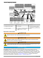
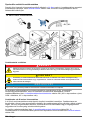
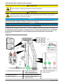
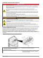
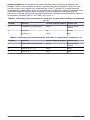
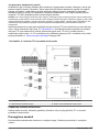
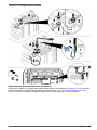
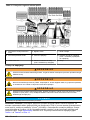
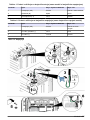
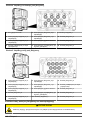
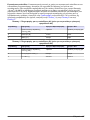
Plumb the sample and drain lines
C A U T I O N
Explosion hazard. Use only the supplied regulator from the manufacturer.
C A U T I O N
Chemical exposure hazard. Dispose of chemicals and wastes in accordance with local, regional and
national regulations.
N O T I C E
Do not connect the drain lines to other lines or backpressure and damage to the analyzer can occur. Make sure
that the drain lines are open to air.
N O T I C E
The pressure regulator is set to a fixed pressure and cannot be changed.
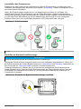
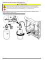
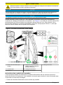
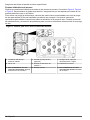
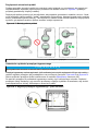
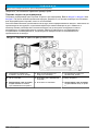
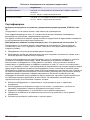
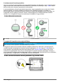
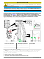
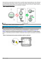
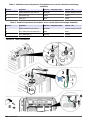
Use the supplied tubing (6 mm), Y-strainer with filter and pressure regulator to plumb the drain and
the sample to the analyzer. Refer to Figure 6. The sample line tubing that goes into the plumbing
access ports must be 6 mm. Tubing of 1/4 in. may be used for the sample line up to the valve/y-
strainer but not into the plumbing access ports of the analyzer.
8
English

Figure 6 Sample and drain lines
1 Sample in (single-stream) 4 Non-adjustable pressure
regulator (set at 4 psi to protect
analyzer)
7 Case drain
2 Shut-off valve 5 Sample bypass drain
3 Y-strainer with filter 6 Chemical drain
Drain line guidelines
Correct installation of the drain lines is important to make sure that all of the liquid is removed from
the instrument. Incorrect installation can cause liquid to go back into the instrument and cause
damage.
• Make the drain lines as short as possible.
• Make sure that the drain lines have a constant slope down.
• Make sure that the drain lines do not have sharp bends and are not pinched.
• Make sure that the drain lines are open to air and are at zero pressure.
Sample line guidelines
Select a good, representative sampling point for the best instrument performance. The sample must
be representative of the entire system.
To prevent erratic readings:
• Collect samples from locations that are sufficiently distant from points of chemical additions to the
process stream.
• Make sure that the samples are sufficiently mixed.
• Make sure that all chemical reactions are complete.
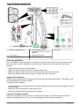
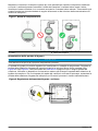
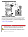
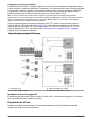
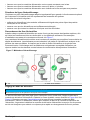
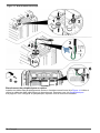
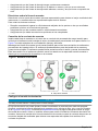
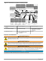
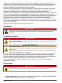
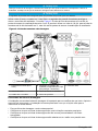
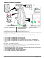
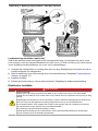
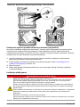
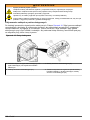
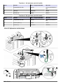
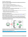
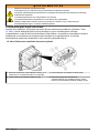
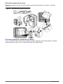
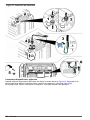
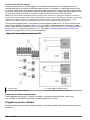
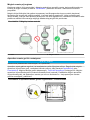
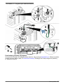
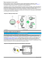
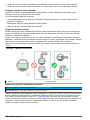
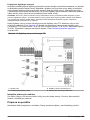
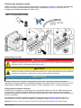
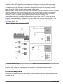
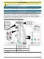
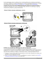
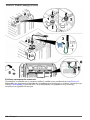
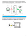
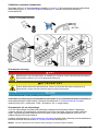
Connect the sample stream
Install each sample line into the center of a larger process pipe to minimize interference from air
bubbles or bottom sediment. Figure 7 shows examples of good and bad installation.
English
9

Keep the sample lines as short as possible to prevent the accumulation of bottom sediment. The
sediment can absorb some of the analyte from the sample and cause low readings. The sediment
can later release the analyte and cause high readings. This exchange with the sediment also causes
a delayed response when the analyte concentration in the sample increases or decreases.
Figure 7 Sampling methods
1 Air 2 Sample flow
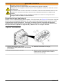
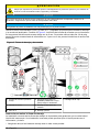
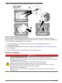
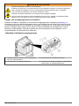
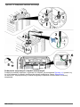
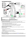
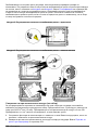
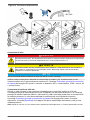
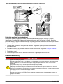
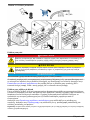
Set the bypass flow rate
N O T I C E
Do not loosen the screw by more than 4 turns for the multi-stream.
The bypass flow can be adjusted when the analyzer is in shutdown mode. Adjust the flow rate of the
sample bypass line with the flow valve as shown in Figure 8 or Figure 9. Refer to Specifications
on page 20 for the sample flow rate range. Use an external meter to measure the flow rate of the
sample bypass line. Increase the flow rate of the sample bypass line when the process stream is far
from the analyzer for a faster response to changes in the process stream.
Figure 8 Bypass flow rate adjustment - one stream
10 English

Figure 9 Bypass flow rate adjustment - multi-streams
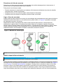
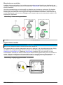
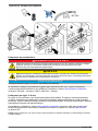
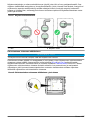
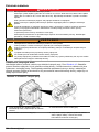
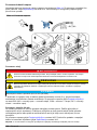
Connect the air purge (optional)
To keep dust and corrosion out of the instrument enclosure, use the optional air-purge kit. Supply
clean, dry instrument-quality air at 0.425 m
3
/hour (15 scfh). The air purge fitting is a 6 mm OD push-
to-connect fitting for plastic tubing.
1. Remove the fan filter and replace it with a plug. Refer to the instructions supplied with the air
purge kit.
2. Find the air purge connection on the instrument enclosure. Refer to Plumbing access ports
on page 7.
3. Install the tubing.
4. Enable the air purge in the instrument menu. Refer to the operations manual.
Electrical installation
D A N G E R
Electrocution hazard.
Use either high voltage (more than 30 V RMS and 42.2 V PEAK or 60 VDC) or low voltage (less than
30 V RMS and 42.2 V PEAK or 60 VDC). Do not use a combination of high and low voltage.
Always remove power to the instrument before making electrical connections.
Do not connect AC power directly to a DC powered instrument.
If this equipment is used outdoors or in potentially wet locations, a Ground Fault Circuit Interrupt
(GFCI/GFI) device must be used for connecting the equipment to its main power source.
Protective Earth Ground (PE) connection is required.
Use only fittings that have the specified environmental enclosure rating. Obey the requirements in the
Specifications section.
English 11

W A R N I N G
Electrical shock and/or fire hazards.
Install the instrument in accordance with local, regional and national regulations.
Externally connected equipment must have an applicable country safety standard assessment.
A local disconnect is needed for a conduit installation.
Make sure to identify the local disconnect clearly for the conduit installation.
For a cord-connected instrument, make sure to install the instrument so that the cord can be
disconnected easily from the supply socket.
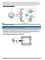
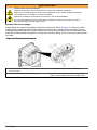
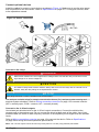
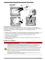
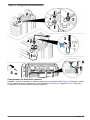
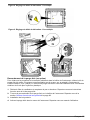
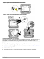
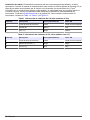
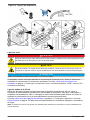
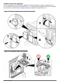
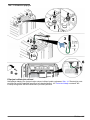
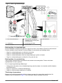
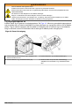
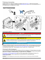
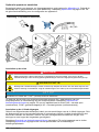
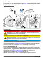
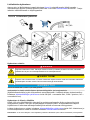
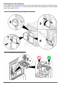
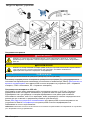
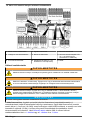
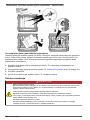
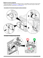
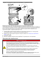
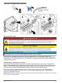
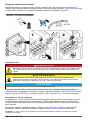
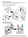
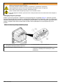
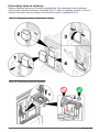
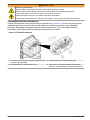
Remove the access plugs
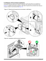
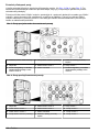
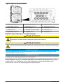
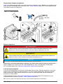
Install cables and conduit through the electrical access ports. Refer to Figure 10. Remove rubber
sealing plugs by pushing them out from inside the enclosure to unlock the seal, and then remove
completely by pulling from the outside. Remove knockouts as necessary from the electrical access
plate with a hammer and screwdriver. To keep the enclosure rating, put a cover on all ports that are
not used.
Figure 10 Electrical access ports
1 Power in (power cord only), no ground plate. Do not
use for conduit.
3 Communication and network modules (8x)
2 Communication and network modules (3x) 4 Power in or out (conduit or power cord), ground
plate, communication and network modules (8x)
12 English

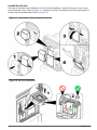
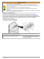
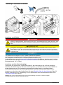
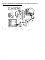
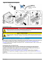
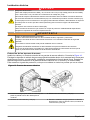
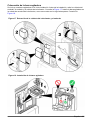
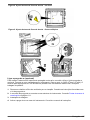
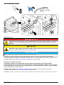
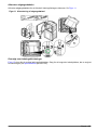
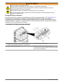
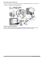
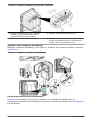
Remove the access cover
Remove the access cover to connect to the wiring terminals. Refer to Figure 11.
Figure 11 Access cover removal
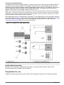
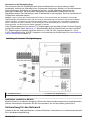
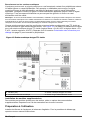
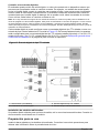
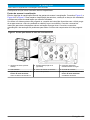
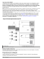
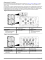
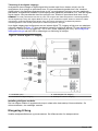
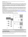
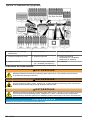
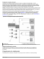
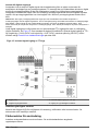
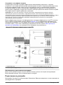
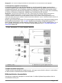
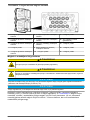
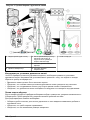
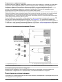
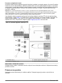
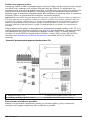
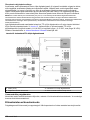
Wiring connections overview
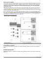
Figure 12 shows all of the possible wiring connections. Make sure to use the wire gauge that is
specified for the connection (refer to Specifications on page 20).
English
13

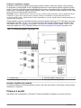
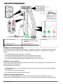
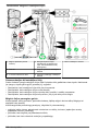
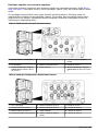
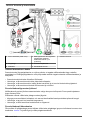
Figure 12 Connections on the main circuit board
1 External controller connection 4 Digital inputs 7 Power out
2 Smart probe connection 5 Power in 8 Power out LED (on = power is
connected to the analyzer)
3 4–20 mA outputs 6 Power switch and LED (on =
analyzer is on)
9 Relays
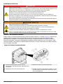
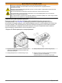
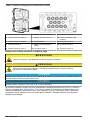
Connect to power
W A R N I N G
Electrocution hazard. Use a crimp‐on ring terminal on the main protective earth connection.
W A R N I N G
Electrical shock and fire hazards. Make sure that the user-supplied power cord and non‐locking plug
meet the applicable country code requirements.
W A R N I N G
Electrocution hazard. Make sure that the protective earth conductor has a low impedance connection of
less than 0.1 ohm. The connected wire conductor must have the same current rating as the AC mains
line conductor.
N O T I C E
The instrument is used for a single phase connection only.
Cord installation: The manufacturer recommends to use the optional cord and sealing gland. Refer
to the maintenance manual for the replacement parts list. For a customer-supplied cord, three
1.0 mm
2
(18 AWG) conductors are required with a waterproof outer jacket, and the cord must be
shorter than 3 meters (10 feet). Use a sealing type strain relief to keep the environmental rating of
the instrument. Refer to Specifications on page 20. To connect power to the instrument, refer to
Table 1 or Table 2 and Figure 13.
14
English

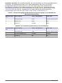
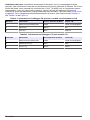
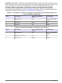
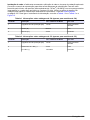
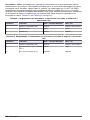
Table 1 AC wiring information (AC models only)
Terminal Description Color—North America Color—EU
1 Protective Earth (PE) Ground Green Green with yellow stripe
2 Neutral (N) White Blue
3 Hot (L1) Black Brown
Table 2 DC wiring information (DC models only)
Terminal Description Color—North America Color—EU
1 Protective Earth (PE) Ground Green Green with yellow stripe
2 24 VDC return (–) Black Black
3 24 VDC (+) Red Red
Figure 13 Power connection
English 15

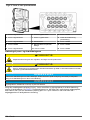
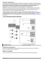
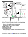
Connect optional devices
Install the cables for output or input devices as shown in Figure 14. Make sure to use the wire gauge
that is specified for the connection. Refer to Specifications on page 20. To configure a device, refer
to the operations manual.
Figure 14 Device connection
Connect to the relays
D A N G E R
Electrocution hazard. Do not mix high and low voltage. Make sure that the relay connections are all
high voltage AC or all low voltage DC.
C A U T I O N
Fire hazard. Relay loads must be resistive. Always limit current to the relays with an external fuse or
breaker. Obey the relay ratings in the Specifications section.
N O T I C E
Wire gauge less than 1.0 mm
2
(18 AWG) is not recommended.
The analyzer contains relays for sample concentration alarms (2x), analyzer system warning and
analyzer system shutdown. Refer to Wiring connections overview on page 13 to connect a device
(NO = normally open, COM = common, NC = normally closed).
Connect to the 4–20 mA outputs
Use twisted pair shielded wire for the 4–20 mA output connections. Connect the shield at the
recorder end or the analyzer end. Do not connect the shield at both ends of the cable. Use of non-
shielded cable can result in radio frequency emission or susceptibility levels higher than the allowed
levels.
Refer to Wiring connections overview on page 13 to connect the device. Refer to Specifications
on page 20 for wiring and load impedance specifications.
Note: The 4-20 mA outputs cannot be used to provide power to a 2-wire (loop-powered) transmitter.
16
English

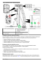
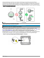
Connect to the digital inputs
The analyzer can receive a digital signal or contact closure from an external device that causes the
analyzer to skip a sample channel. For example, a flow meter can send a digital signal when the
sample flow is low and the analyzer skips the applicable sample channel. The analyzer continues to
skip the applicable sample channel until the digital signal stops. All sample channels cannot be
skipped. A minimum of one sample channel must be in use.
Note: If all of the sample channels have no sample, the user cannot put the analyzer in shutdown mode with the
digital inputs. To put the instrument into shutdown mode or back into operation remotely, use the optional Modbus
module and write to Modbus register 49937. Write 40007 (decimal) to put the analyzer in shutdown mode. Write
40008 (decimal) to put the analyzer back into operation.
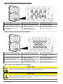
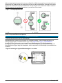
Each digital input can be configured as an isolated TTL type digital input or as a relay/open-collector
type input. Refer to Figure 15. By default, the jumpers are set for isolated TTL type digital input (logic
low = 0 to 0.8 VDC and logic high = 2 to 5 VDC; maximum voltage 30 VDC). Refer to Wiring
connections overview on page 13 to connect the device.
Figure 15 Isolated TTL type digital input
1 Jumper (12x) 3 Isolated TTL type digital input
2 Digital input connectors 4 Relay/Open-collector type input
Install additional modules
Modules can be added for additional output, relay or communications options. Refer to the
documentation that is supplied with the module.
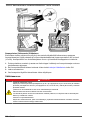
Preparation for use
Install the analyzer bottles and stir bar. Refer to the operations manual for the startup procedure.
English
17

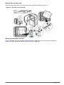
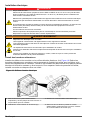
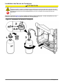
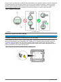
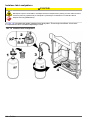
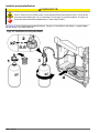
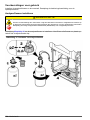
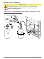
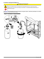
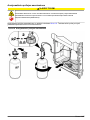
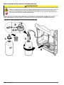
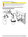
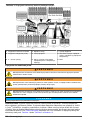
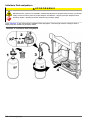
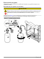
Install the analyzer bottles
C A U T I O N
Chemical exposure hazard. Obey laboratory safety procedures and wear all of the personal protective
equipment appropriate to the chemicals that are handled. Refer to the current safety data sheets
(MSDS/SDS) for safety protocols.
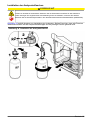
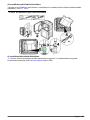
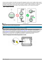
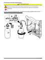
Refer to Figure 16 to install the analyzer bottles. Make sure to identify all bottles and put the
applicable cap on the applicable bottle.
Figure 16 Analyzer bottle installation
18 English

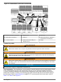
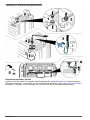
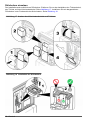
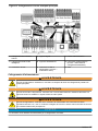
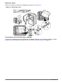
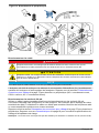
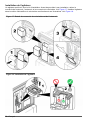
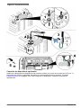
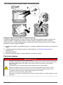
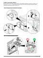
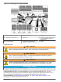
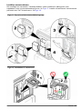
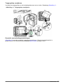
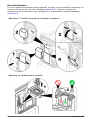
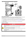
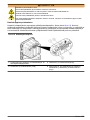
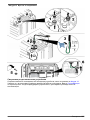
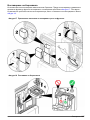
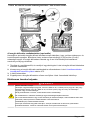
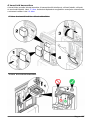
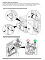
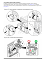
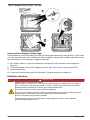
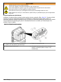
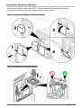
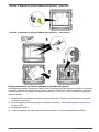
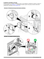
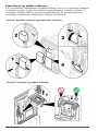
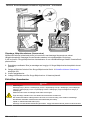
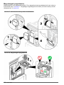
Install the stir bar
A stir bar is included in the installation kit. Prior to the installation, remove the funnel cover, funnel
and colorimeter cover. Refer to Figure 17. Install the stir bar in the sample cell of the colorimeter as
shown in the illustrated steps. Refer to Figure 18.
Figure 17 Colorimeter cover and funnel removal
Figure 18 Stir bar installation
English 19

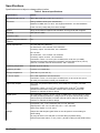
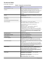
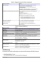
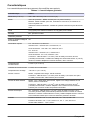
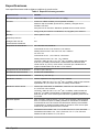
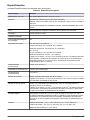
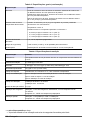
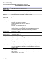
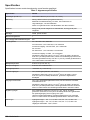
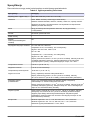
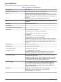
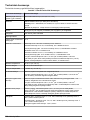
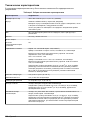
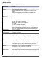
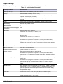
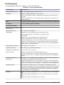
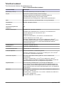
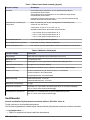
Specifications
Specifications are subject to change without notice.
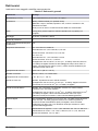
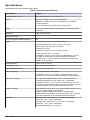
Table 3 General specifications
Specification Details
Dimensions (W x D x H) 452 x 360 x 804 mm (17.8 x 14.2 x 31.7 in.)
Enclosure Rating: NEMA 4x/IP56 (with closed doors)
Material: PC/ABS case, PC door, PC hinges and latches, 316 SST hardware
Indoor use only. Keep away from direct sunlight.
Weight 20 kg (45 lb) without reagents and standards, 36.3 kg (80 lb) with reagents
Mounting Wall, panel or table
Protection class I
Pollution degree/installation
category
2/II
Power requirements AC: 100–240 VAC, 50/60 Hz
AC instrument: 0.5 A nominal, 8.3 A maximum
Accessory output: 100–240 VAC, 5.0 A maximum
DC: 24 VDC
DC instrument: 1.2 A nominal, 9 A maximum
Accessory output: 24 VDC, 1.6 A maximum
Connection: 0.82 to 1.31 mm
2
(18 to 16 AWG) wire, 0.82 mm
2
(18 AWG)
stranded recommended; field wiring insulation must be rated to 65°C (149 ºF)
minimum, insulation rated for wet locations, 300 V minimum.
Operating temperature 5 to 50 °C (41 to 122 °F)
Operating humidity 5 to 95% non-condensing
Storage temperature –20 to 60 °C (–4 to 140 °F)
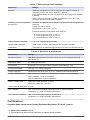
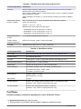
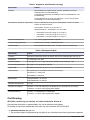
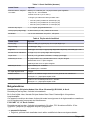
4–20 mA outputs Four; load impedance: 600 Ω maximum
Connection: 0.33 to 1.31 mm
2
(22 to 16 AWG) wire, 0.33 to 0.52 mm
2
(22 to
20 AWG) recommended, twisted pair shielded wire
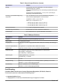
Alarm relay outputs Four; type: not powered SPDT relays, each rated at 5 A resistive, 240 VAC
maximum
Connection: 0.82 to 1.31 mm
2
(18 to 16 AWG) wire, 0.82 mm
2
(18 AWG)
stranded recommended, insulation rated for 300 V minimum and for wet
locations to maintain enclosure ratings.
Digital inputs Six; connection: 0.33 to 1.31 mm
2
(22 to 16 AWG) wire, 0.33 to 0.52 mm
2
(22 to
20 AWG) stranded (isolated DC voltage input or an open-collector/relay contact
closure input) recommended, insulation rated for 300 V minimum and for wet
locations to maintain enclosure ratings.
Fuses Input power—AC: T 1.6 A, 250 VAC; DC: T 6.3 A, 250 VAC
Output power—AC: T 5.0 A, 250 VAC; DC: T 1.6 A, 250 VAC
Alarm relay outputs: T 5.0 A, 250 V
Fittings Sample line and sample bypass drain: 6 mm OD push-to-connect fitting for
plastic tubing
Air purge air inlet: 6 mm OD push-to-connect fitting for plastic tubing
Chemical and case drains: 11 mm (7/16 in.) ID slip-on fitting for soft plastic tubing
20 English
Pagina se încarcă...
Pagina se încarcă...
Pagina se încarcă...
Pagina se încarcă...
Pagina se încarcă...
Pagina se încarcă...
Pagina se încarcă...
Pagina se încarcă...
Pagina se încarcă...
Pagina se încarcă...
Pagina se încarcă...
Pagina se încarcă...
Pagina se încarcă...
Pagina se încarcă...
Pagina se încarcă...
Pagina se încarcă...
Pagina se încarcă...
Pagina se încarcă...
Pagina se încarcă...
Pagina se încarcă...
Pagina se încarcă...
Pagina se încarcă...
Pagina se încarcă...
Pagina se încarcă...
Pagina se încarcă...
Pagina se încarcă...
Pagina se încarcă...
Pagina se încarcă...
Pagina se încarcă...
Pagina se încarcă...
Pagina se încarcă...
Pagina se încarcă...
Pagina se încarcă...
Pagina se încarcă...
Pagina se încarcă...
Pagina se încarcă...
Pagina se încarcă...
Pagina se încarcă...
Pagina se încarcă...
Pagina se încarcă...
Pagina se încarcă...
Pagina se încarcă...
Pagina se încarcă...
Pagina se încarcă...
Pagina se încarcă...
Pagina se încarcă...
Pagina se încarcă...
Pagina se încarcă...
Pagina se încarcă...
Pagina se încarcă...
Pagina se încarcă...
Pagina se încarcă...
Pagina se încarcă...
Pagina se încarcă...
Pagina se încarcă...
Pagina se încarcă...
Pagina se încarcă...
Pagina se încarcă...
Pagina se încarcă...
Pagina se încarcă...
Pagina se încarcă...
Pagina se încarcă...
Pagina se încarcă...
Pagina se încarcă...
Pagina se încarcă...
Pagina se încarcă...
Pagina se încarcă...
Pagina se încarcă...
Pagina se încarcă...
Pagina se încarcă...
Pagina se încarcă...
Pagina se încarcă...
Pagina se încarcă...
Pagina se încarcă...
Pagina se încarcă...
Pagina se încarcă...
Pagina se încarcă...
Pagina se încarcă...
Pagina se încarcă...
Pagina se încarcă...
Pagina se încarcă...
Pagina se încarcă...
Pagina se încarcă...
Pagina se încarcă...
Pagina se încarcă...
Pagina se încarcă...
Pagina se încarcă...
Pagina se încarcă...
Pagina se încarcă...
Pagina se încarcă...
Pagina se încarcă...
Pagina se încarcă...
Pagina se încarcă...
Pagina se încarcă...
Pagina se încarcă...
Pagina se încarcă...
Pagina se încarcă...
Pagina se încarcă...
Pagina se încarcă...
Pagina se încarcă...
Pagina se încarcă...
Pagina se încarcă...
Pagina se încarcă...
Pagina se încarcă...
Pagina se încarcă...
Pagina se încarcă...
Pagina se încarcă...
Pagina se încarcă...
Pagina se încarcă...
Pagina se încarcă...
Pagina se încarcă...
Pagina se încarcă...
Pagina se încarcă...
Pagina se încarcă...
Pagina se încarcă...
Pagina se încarcă...
Pagina se încarcă...
Pagina se încarcă...
Pagina se încarcă...
Pagina se încarcă...
Pagina se încarcă...
Pagina se încarcă...
Pagina se încarcă...
Pagina se încarcă...
Pagina se încarcă...
Pagina se încarcă...
Pagina se încarcă...
Pagina se încarcă...
Pagina se încarcă...
Pagina se încarcă...
Pagina se încarcă...
Pagina se încarcă...
Pagina se încarcă...
Pagina se încarcă...
Pagina se încarcă...
Pagina se încarcă...
Pagina se încarcă...
Pagina se încarcă...
Pagina se încarcă...
Pagina se încarcă...
Pagina se încarcă...
Pagina se încarcă...
Pagina se încarcă...
Pagina se încarcă...
Pagina se încarcă...
Pagina se încarcă...
Pagina se încarcă...
Pagina se încarcă...
Pagina se încarcă...
Pagina se încarcă...
Pagina se încarcă...
Pagina se încarcă...
Pagina se încarcă...
Pagina se încarcă...
Pagina se încarcă...
Pagina se încarcă...
Pagina se încarcă...
Pagina se încarcă...
Pagina se încarcă...
Pagina se încarcă...
Pagina se încarcă...
Pagina se încarcă...
Pagina se încarcă...
Pagina se încarcă...
Pagina se încarcă...
Pagina se încarcă...
Pagina se încarcă...
Pagina se încarcă...
Pagina se încarcă...
Pagina se încarcă...
Pagina se încarcă...
Pagina se încarcă...
Pagina se încarcă...
Pagina se încarcă...
Pagina se încarcă...
Pagina se încarcă...
Pagina se încarcă...
Pagina se încarcă...
Pagina se încarcă...
Pagina se încarcă...
Pagina se încarcă...
Pagina se încarcă...
Pagina se încarcă...
Pagina se încarcă...
Pagina se încarcă...
Pagina se încarcă...
Pagina se încarcă...
Pagina se încarcă...
Pagina se încarcă...
Pagina se încarcă...
Pagina se încarcă...
Pagina se încarcă...
Pagina se încarcă...
Pagina se încarcă...
Pagina se încarcă...
Pagina se încarcă...
Pagina se încarcă...
Pagina se încarcă...
Pagina se încarcă...
Pagina se încarcă...
Pagina se încarcă...
Pagina se încarcă...
Pagina se încarcă...
Pagina se încarcă...
Pagina se încarcă...
Pagina se încarcă...
Pagina se încarcă...
Pagina se încarcă...
Pagina se încarcă...
Pagina se încarcă...
Pagina se încarcă...
Pagina se încarcă...
Pagina se încarcă...
Pagina se încarcă...
Pagina se încarcă...
Pagina se încarcă...
Pagina se încarcă...
Pagina se încarcă...
Pagina se încarcă...
Pagina se încarcă...
Pagina se încarcă...
Pagina se încarcă...
Pagina se încarcă...
Pagina se încarcă...
Pagina se încarcă...
Pagina se încarcă...
Pagina se încarcă...
Pagina se încarcă...
Pagina se încarcă...
Pagina se încarcă...
Pagina se încarcă...
Pagina se încarcă...
Pagina se încarcă...
Pagina se încarcă...
Pagina se încarcă...
Pagina se încarcă...
Pagina se încarcă...
Pagina se încarcă...
Pagina se încarcă...
Pagina se încarcă...
Pagina se încarcă...
Pagina se încarcă...
Pagina se încarcă...
Pagina se încarcă...
Pagina se încarcă...
Pagina se încarcă...
Pagina se încarcă...
Pagina se încarcă...
Pagina se încarcă...
Pagina se încarcă...
Pagina se încarcă...
Pagina se încarcă...
Pagina se încarcă...
Pagina se încarcă...
Pagina se încarcă...
Pagina se încarcă...
Pagina se încarcă...
Pagina se încarcă...
Pagina se încarcă...
Pagina se încarcă...
Pagina se încarcă...
Pagina se încarcă...
Pagina se încarcă...
Pagina se încarcă...
Pagina se încarcă...
Pagina se încarcă...
Pagina se încarcă...
Pagina se încarcă...
Pagina se încarcă...
Pagina se încarcă...
Pagina se încarcă...
Pagina se încarcă...
Pagina se încarcă...
Pagina se încarcă...
Pagina se încarcă...
Pagina se încarcă...
Pagina se încarcă...
Pagina se încarcă...
Pagina se încarcă...
Pagina se încarcă...
Pagina se încarcă...
Pagina se încarcă...
Pagina se încarcă...
Pagina se încarcă...
Pagina se încarcă...
Pagina se încarcă...
Pagina se încarcă...
Pagina se încarcă...
Pagina se încarcă...
Pagina se încarcă...
Pagina se încarcă...
Pagina se încarcă...
Pagina se încarcă...
Pagina se încarcă...
Pagina se încarcă...
Pagina se încarcă...
Pagina se încarcă...
Pagina se încarcă...
Pagina se încarcă...
Pagina se încarcă...
Pagina se încarcă...
Pagina se încarcă...
Pagina se încarcă...
Pagina se încarcă...
Pagina se încarcă...
Pagina se încarcă...
Pagina se încarcă...
Pagina se încarcă...
Pagina se încarcă...
Pagina se încarcă...
Pagina se încarcă...
Pagina se încarcă...
Pagina se încarcă...
Pagina se încarcă...
Pagina se încarcă...
Pagina se încarcă...
Pagina se încarcă...
Pagina se încarcă...
Pagina se încarcă...
Pagina se încarcă...
Pagina se încarcă...
Pagina se încarcă...
Pagina se încarcă...
Pagina se încarcă...
Pagina se încarcă...
Pagina se încarcă...
Pagina se încarcă...
Pagina se încarcă...
Pagina se încarcă...
Pagina se încarcă...
Pagina se încarcă...
Pagina se încarcă...
Pagina se încarcă...
Pagina se încarcă...
Pagina se încarcă...
Pagina se încarcă...
Pagina se încarcă...
Pagina se încarcă...
Pagina se încarcă...
Pagina se încarcă...
Pagina se încarcă...
Pagina se încarcă...
Pagina se încarcă...
Pagina se încarcă...
Pagina se încarcă...
Pagina se încarcă...
Pagina se încarcă...
Pagina se încarcă...
Pagina se încarcă...
Pagina se încarcă...
Pagina se încarcă...
Pagina se încarcă...
Pagina se încarcă...
Pagina se încarcă...
Pagina se încarcă...
Pagina se încarcă...
Pagina se încarcă...
Pagina se încarcă...
Pagina se încarcă...
Pagina se încarcă...
Pagina se încarcă...
Pagina se încarcă...
Pagina se încarcă...
Pagina se încarcă...
Pagina se încarcă...
Pagina se încarcă...
Pagina se încarcă...
Pagina se încarcă...
Pagina se încarcă...
Pagina se încarcă...
Pagina se încarcă...
Pagina se încarcă...
Pagina se încarcă...
Pagina se încarcă...
Pagina se încarcă...
Pagina se încarcă...
Pagina se încarcă...
Pagina se încarcă...
Pagina se încarcă...
Pagina se încarcă...
Pagina se încarcă...
Pagina se încarcă...
Pagina se încarcă...
Pagina se încarcă...
Pagina se încarcă...
Pagina se încarcă...
Pagina se încarcă...
Pagina se încarcă...
Pagina se încarcă...
Pagina se încarcă...
Pagina se încarcă...
Pagina se încarcă...
Pagina se încarcă...
Pagina se încarcă...
Pagina se încarcă...
Pagina se încarcă...
Pagina se încarcă...
Pagina se încarcă...
Pagina se încarcă...
Pagina se încarcă...
Pagina se încarcă...
Pagina se încarcă...
Pagina se încarcă...
Pagina se încarcă...
Pagina se încarcă...
Pagina se încarcă...
Pagina se încarcă...
Pagina se încarcă...
Pagina se încarcă...
Pagina se încarcă...
Pagina se încarcă...
Pagina se încarcă...
Pagina se încarcă...
Pagina se încarcă...
Pagina se încarcă...
Pagina se încarcă...
Pagina se încarcă...
Pagina se încarcă...
Pagina se încarcă...
Pagina se încarcă...
Pagina se încarcă...
Pagina se încarcă...
Pagina se încarcă...
Pagina se încarcă...
Pagina se încarcă...
Pagina se încarcă...
Pagina se încarcă...
Pagina se încarcă...
Pagina se încarcă...
Pagina se încarcă...
Pagina se încarcă...
Pagina se încarcă...
Pagina se încarcă...
Pagina se încarcă...
Pagina se încarcă...
Pagina se încarcă...
Pagina se încarcă...
Pagina se încarcă...
Pagina se încarcă...
Pagina se încarcă...
Pagina se încarcă...
Pagina se încarcă...
Pagina se încarcă...
Pagina se încarcă...
Pagina se încarcă...
Pagina se încarcă...
Pagina se încarcă...
Pagina se încarcă...
Pagina se încarcă...
Pagina se încarcă...
Pagina se încarcă...
Pagina se încarcă...
Pagina se încarcă...
Pagina se încarcă...
Pagina se încarcă...
Pagina se încarcă...
Pagina se încarcă...
Pagina se încarcă...
-
 1
1
-
 2
2
-
 3
3
-
 4
4
-
 5
5
-
 6
6
-
 7
7
-
 8
8
-
 9
9
-
 10
10
-
 11
11
-
 12
12
-
 13
13
-
 14
14
-
 15
15
-
 16
16
-
 17
17
-
 18
18
-
 19
19
-
 20
20
-
 21
21
-
 22
22
-
 23
23
-
 24
24
-
 25
25
-
 26
26
-
 27
27
-
 28
28
-
 29
29
-
 30
30
-
 31
31
-
 32
32
-
 33
33
-
 34
34
-
 35
35
-
 36
36
-
 37
37
-
 38
38
-
 39
39
-
 40
40
-
 41
41
-
 42
42
-
 43
43
-
 44
44
-
 45
45
-
 46
46
-
 47
47
-
 48
48
-
 49
49
-
 50
50
-
 51
51
-
 52
52
-
 53
53
-
 54
54
-
 55
55
-
 56
56
-
 57
57
-
 58
58
-
 59
59
-
 60
60
-
 61
61
-
 62
62
-
 63
63
-
 64
64
-
 65
65
-
 66
66
-
 67
67
-
 68
68
-
 69
69
-
 70
70
-
 71
71
-
 72
72
-
 73
73
-
 74
74
-
 75
75
-
 76
76
-
 77
77
-
 78
78
-
 79
79
-
 80
80
-
 81
81
-
 82
82
-
 83
83
-
 84
84
-
 85
85
-
 86
86
-
 87
87
-
 88
88
-
 89
89
-
 90
90
-
 91
91
-
 92
92
-
 93
93
-
 94
94
-
 95
95
-
 96
96
-
 97
97
-
 98
98
-
 99
99
-
 100
100
-
 101
101
-
 102
102
-
 103
103
-
 104
104
-
 105
105
-
 106
106
-
 107
107
-
 108
108
-
 109
109
-
 110
110
-
 111
111
-
 112
112
-
 113
113
-
 114
114
-
 115
115
-
 116
116
-
 117
117
-
 118
118
-
 119
119
-
 120
120
-
 121
121
-
 122
122
-
 123
123
-
 124
124
-
 125
125
-
 126
126
-
 127
127
-
 128
128
-
 129
129
-
 130
130
-
 131
131
-
 132
132
-
 133
133
-
 134
134
-
 135
135
-
 136
136
-
 137
137
-
 138
138
-
 139
139
-
 140
140
-
 141
141
-
 142
142
-
 143
143
-
 144
144
-
 145
145
-
 146
146
-
 147
147
-
 148
148
-
 149
149
-
 150
150
-
 151
151
-
 152
152
-
 153
153
-
 154
154
-
 155
155
-
 156
156
-
 157
157
-
 158
158
-
 159
159
-
 160
160
-
 161
161
-
 162
162
-
 163
163
-
 164
164
-
 165
165
-
 166
166
-
 167
167
-
 168
168
-
 169
169
-
 170
170
-
 171
171
-
 172
172
-
 173
173
-
 174
174
-
 175
175
-
 176
176
-
 177
177
-
 178
178
-
 179
179
-
 180
180
-
 181
181
-
 182
182
-
 183
183
-
 184
184
-
 185
185
-
 186
186
-
 187
187
-
 188
188
-
 189
189
-
 190
190
-
 191
191
-
 192
192
-
 193
193
-
 194
194
-
 195
195
-
 196
196
-
 197
197
-
 198
198
-
 199
199
-
 200
200
-
 201
201
-
 202
202
-
 203
203
-
 204
204
-
 205
205
-
 206
206
-
 207
207
-
 208
208
-
 209
209
-
 210
210
-
 211
211
-
 212
212
-
 213
213
-
 214
214
-
 215
215
-
 216
216
-
 217
217
-
 218
218
-
 219
219
-
 220
220
-
 221
221
-
 222
222
-
 223
223
-
 224
224
-
 225
225
-
 226
226
-
 227
227
-
 228
228
-
 229
229
-
 230
230
-
 231
231
-
 232
232
-
 233
233
-
 234
234
-
 235
235
-
 236
236
-
 237
237
-
 238
238
-
 239
239
-
 240
240
-
 241
241
-
 242
242
-
 243
243
-
 244
244
-
 245
245
-
 246
246
-
 247
247
-
 248
248
-
 249
249
-
 250
250
-
 251
251
-
 252
252
-
 253
253
-
 254
254
-
 255
255
-
 256
256
-
 257
257
-
 258
258
-
 259
259
-
 260
260
-
 261
261
-
 262
262
-
 263
263
-
 264
264
-
 265
265
-
 266
266
-
 267
267
-
 268
268
-
 269
269
-
 270
270
-
 271
271
-
 272
272
-
 273
273
-
 274
274
-
 275
275
-
 276
276
-
 277
277
-
 278
278
-
 279
279
-
 280
280
-
 281
281
-
 282
282
-
 283
283
-
 284
284
-
 285
285
-
 286
286
-
 287
287
-
 288
288
-
 289
289
-
 290
290
-
 291
291
-
 292
292
-
 293
293
-
 294
294
-
 295
295
-
 296
296
-
 297
297
-
 298
298
-
 299
299
-
 300
300
-
 301
301
-
 302
302
-
 303
303
-
 304
304
-
 305
305
-
 306
306
-
 307
307
-
 308
308
-
 309
309
-
 310
310
-
 311
311
-
 312
312
-
 313
313
-
 314
314
-
 315
315
-
 316
316
-
 317
317
-
 318
318
-
 319
319
-
 320
320
-
 321
321
-
 322
322
-
 323
323
-
 324
324
-
 325
325
-
 326
326
-
 327
327
-
 328
328
-
 329
329
-
 330
330
-
 331
331
-
 332
332
-
 333
333
-
 334
334
-
 335
335
-
 336
336
-
 337
337
-
 338
338
-
 339
339
-
 340
340
-
 341
341
-
 342
342
-
 343
343
-
 344
344
-
 345
345
-
 346
346
-
 347
347
-
 348
348
-
 349
349
-
 350
350
-
 351
351
-
 352
352
-
 353
353
-
 354
354
-
 355
355
-
 356
356
-
 357
357
-
 358
358
-
 359
359
-
 360
360
-
 361
361
-
 362
362
-
 363
363
-
 364
364
-
 365
365
-
 366
366
-
 367
367
-
 368
368
-
 369
369
-
 370
370
-
 371
371
-
 372
372
-
 373
373
-
 374
374
-
 375
375
-
 376
376
-
 377
377
-
 378
378
-
 379
379
-
 380
380
-
 381
381
-
 382
382
-
 383
383
-
 384
384
-
 385
385
-
 386
386
-
 387
387
-
 388
388
-
 389
389
-
 390
390
-
 391
391
-
 392
392
-
 393
393
-
 394
394
-
 395
395
-
 396
396
-
 397
397
-
 398
398
-
 399
399
-
 400
400
-
 401
401
-
 402
402
-
 403
403
-
 404
404
-
 405
405
-
 406
406
-
 407
407
-
 408
408
-
 409
409
-
 410
410
-
 411
411
-
 412
412
-
 413
413
-
 414
414
-
 415
415
-
 416
416
-
 417
417
-
 418
418
-
 419
419
-
 420
420
-
 421
421
-
 422
422
-
 423
423
-
 424
424
-
 425
425
-
 426
426
-
 427
427
-
 428
428
-
 429
429
-
 430
430
-
 431
431
-
 432
432
-
 433
433
-
 434
434
-
 435
435
-
 436
436
-
 437
437
-
 438
438
-
 439
439
-
 440
440
-
 441
441
-
 442
442
-
 443
443
-
 444
444
-
 445
445
-
 446
446
-
 447
447
-
 448
448
-
 449
449
-
 450
450
-
 451
451
-
 452
452
-
 453
453
-
 454
454
-
 455
455
-
 456
456
-
 457
457
-
 458
458
-
 459
459
-
 460
460
-
 461
461
-
 462
462
-
 463
463
-
 464
464
-
 465
465
-
 466
466
-
 467
467
-
 468
468
-
 469
469
-
 470
470
-
 471
471
-
 472
472
-
 473
473
-
 474
474
-
 475
475
-
 476
476
-
 477
477
-
 478
478


Hach Polymetron 9610sc SiO2 Ghid de instalare
- Tip
- Ghid de instalare
în alte limbi
Lucrări înrudite
-
 Hach POLYMETRON 8810 ISE Basic User Manual
-
 Hach POLYMETRON 8810 ISE Basic User Manual
-
 Hach POLYMETRON 8810 ORP Basic User Manual
-
 Hach Polymetron 9610sc Maintenance And Troubleshooting Manual
-
 Hach Polymetron 9611sc PO43-LR Instrucțiuni de utilizare
-
 Hach QbD1200 AutoSampler Manual de utilizare
-
 Hach QbD1200 AutoSampler Manual de utilizare
-
 Hach 9586sc Basic User Manual
-
 Hach ORBISPHERE 3658 Basic User Manual
-
 Hach LANGE LT20 Basic User Manual


