Hach Lange 4-20 mA Module Manual de utilizare
- Tip
- Manual de utilizare

DOC023.98.80254
4–20 mA Module
05/2013, Edition 1
User Manual
Bedienungsanleitung
Manuale dell'utente
Manuel d'utilisation
Manual del usuario
Manual do utilizador
Uživatelská příručka
Gebruikershandleiding
Brugsanvisning
Instrukcja obsługi
Bruksanvisning
Käyttäjän käsikirja
Ръководство на потребителя
Használati útmutató
Manual de utilizare
Naudotojo vadovas
Руководство пользователя
Kullanım Kılavuzu
Návod na obsluhu
Navodila za uporabo
Korisnički priručnik
Εγχειρίδιο χρήσης
Kasutusjuhend

English...................................................................................................................................................................................................3
Deutsch...............................................................................................................................................................................................12
Italiano.................................................................................................................................................................................................22
Français..............................................................................................................................................................................................31
Español...............................................................................................................................................................................................41
Português..........................................................................................................................................................................................51
Čeština................................................................................................................................................................................................60
Nederlands........................................................................................................................................................................................70
Dansk...................................................................................................................................................................................................80
Polski...................................................................................................................................................................................................90
Svenska..............................................................................................................................................................................................99
Suomi.................................................................................................................................................................................................108
български.......................................................................................................................................................................................117
Magyar..............................................................................................................................................................................................127
Română............................................................................................................................................................................................136
lietuvių kalba...................................................................................................................................................................................145
Русский............................................................................................................................................................................................155
Türkçe................................................................................................................................................................................................164
Slovenský jazyk............................................................................................................................................................................173
Slovenski..........................................................................................................................................................................................183
Hrvatski.............................................................................................................................................................................................193
Ελληνικά...........................................................................................................................................................................................203
eesti keel..........................................................................................................................................................................................213
2

Table of contents
Specifications on page 3
General information on page 3
Installation on page 6
Operation on page 9
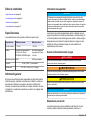
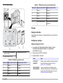
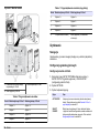
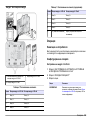
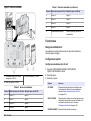
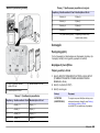
Specifications
Specifications are subject to change without notice.
Specification Input module Output module
Current usage < 100 mA < 150 mA
Outputs Analog/Digital inputs (0–
20 mA or 4–20 mA), INPUT
or digital INPUT
Two analog current outputs
(0–20 mA or 4–20 mA)
Internal resistance 180 Ω 500 Ω maximum
Terminal 2.5 mm
2
(AWG 11) maximum
Dimensions 23 x 100 x 115 mm (1 x 4 x 4.5 in.)
General information
In no event will the manufacturer be liable for direct, indirect, special,
incidental or consequential damages resulting from any defect or
omission in this manual. The manufacturer reserves the right to make
changes in this manual and the products it describes at any time, without
notice or obligation. Revised editions are found on the manufacturer’s
website.
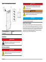
Safety information
N O T I C E
The manufacturer is not responsible for any damages due to misapplication or
misuse of this product including, without limitation, direct, incidental and
consequential damages, and disclaims such damages to the full extent permitted
under applicable law. The user is solely responsible to identify critical application
risks and install appropriate mechanisms to protect processes during a possible
equipment malfunction.
Please read this entire manual before unpacking, setting up or operating
this equipment. Pay attention to all danger and caution statements.
Failure to do so could result in serious injury to the operator or damage
to the equipment.
Make sure that the protection provided by this equipment is not impaired.
Do not use or install this equipment in any manner other than that
specified in this manual.
Use of hazard information
D A N G E R
Indicates a potentially or imminently hazardous situation which, if not avoided, will
result in death or serious injury.
W A R N I N G
Indicates a potentially or imminently hazardous situation which, if not avoided,
could result in death or serious injury.
C A U T I O N
Indicates a potentially hazardous situation that may result in minor or moderate
injury.
N O T I C E
Indicates a situation which, if not avoided, may cause damage to the instrument.
Information that requires special emphasis.
English 3

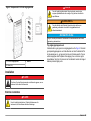
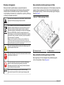
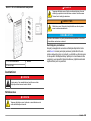
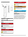
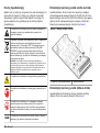
Precautionary labels
Read all labels and tags attached to the instrument. Personal injury or
damage to the instrument could occur if not observed. A symbol on the
instrument is referenced in the manual with a precautionary statement.
This symbol, if noted on the instrument, references the instruction
manual for operation and/or safety information.
Electrical equipment marked with this symbol may not be disposed of
in European public disposal systems after 12 August of 2005. In
conformity with European local and national regulations (EU Directive
2002/96/EC), European electrical equipment users must now return
old or end-of-life equipment to the Producer for disposal at no charge
to the user.
Note: For return for recycling, please contact the equipment producer or supplier
for instructions on how to return end-of-life equipment, producer-supplied
electrical accessories, and all auxiliary items for proper disposal.
This symbol indicates that a risk of electrical shock and/or
electrocution exists.
This symbol indicates the need for protective eye wear.
This symbol indicates that the marked item requires a protective earth
connection. If the instrument is not supplied with a ground plug on a
cord, make the protective earth connection to the protective
conductor terminal.
This symbol, when noted on the product, identifies the location of a
fuse or current limiting device.
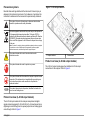
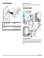
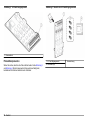
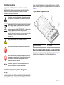
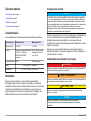
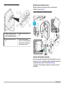
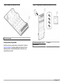
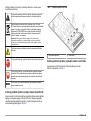
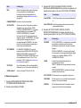
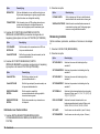
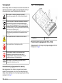
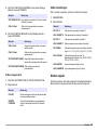
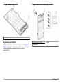
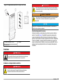
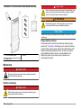
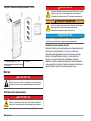
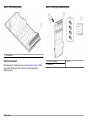
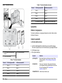
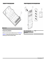
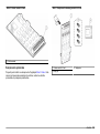
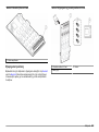
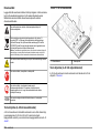
Product overview (4–20 mA input module)
The 4–20 mA input module lets the analyzer accept external digital
signals and analog signals (0–20 mA/4–20 mA). A closed jumper lets a
digital signal come through and an opened jumper lets an analog signal
come through. Refer to Figure 1.
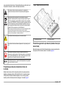
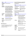
Figure 1 4–20 mA input module
1 Jumper switches 2 Terminal block
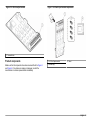
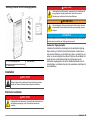
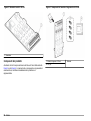
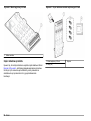
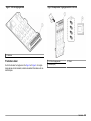
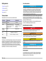
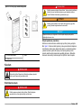
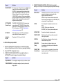
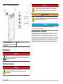
Product overview (4–20 mA output module)
The 4–20 mA output module gives four additional 4–20 mA output
connections to the analyzer. Refer to Figure 2.
4 English

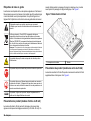
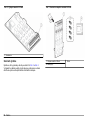
Figure 2 4–20 mA output module
1 Terminal block
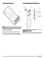
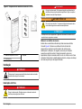
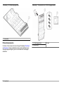
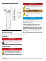
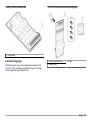
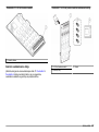
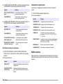
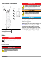
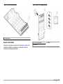
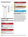
Product components
Make sure that all components have been received. Refer to Figure 3
and Figure 4. If any items are missing or damaged, contact the
manufacturer or a sales representative immediately.
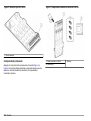
Figure 3 4–20 mA input module components
1 4–20 mA input module 3 Label
2 Screws (4x)
English 5

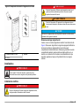
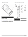
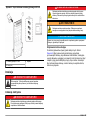
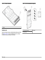
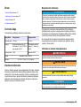
Figure 4 4–20 mA output module components
1 4–20 mA output module 3 Label
2 Screws (4x)
Installation
D A N G E R
Multiple hazards. Only qualified personnel must conduct the tasks
described in this section of the document.
Electrical installation
D A N G E R
Electrocution hazard. Always remove power to the instrument before
making electrical connections.
D A N G E R
Electrocution hazard. Use only fittings that have the specified
environmental enclosure rating. Obey the requirements in the
Specifications section.
W A R N I N G
Electrical shock hazard. Externally connected equipment must have an
applicable country safety standard assessment.
N O T I C E
Make sure that the equipment is connected to the instrument in accordance with
local, regional and national requirements.
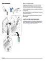
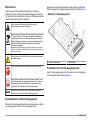
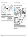
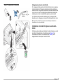
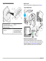
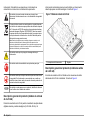
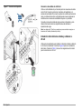
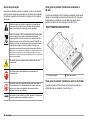
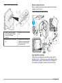
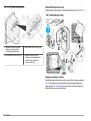
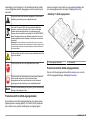
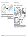
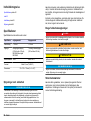
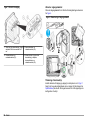
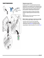
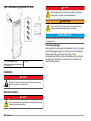
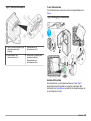
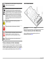
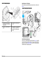
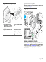
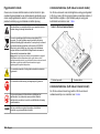
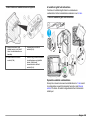
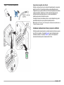
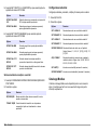
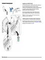
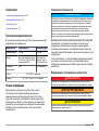
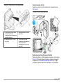
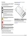
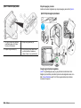
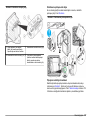
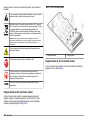
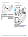
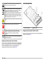
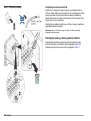
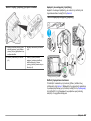
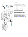
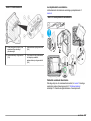
Remove the access plugs
Install cables and conduit through the electrical access ports. Refer to
Figure 5. Remove rubber sealing plugs by pushing them out from inside
the enclosure to unlock the seal, and then remove completely by pulling
from the outside. Remove knockouts as necessary from the electrical
access plate with a hammer and screwdriver. To keep the enclosure
rating, put a cover on all ports that are not used.
6 English

Figure 5 Electrical access ports
1 Power in (power cord only), no
ground plate. Do not use for
conduit.
3 Communication and network
modules (8x)
2 Communication and network
modules (3x)
4 Power in or out (conduit or power
cord), ground plate, communication
and network modules (8x)
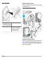
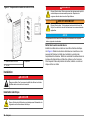
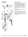
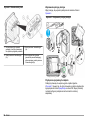
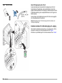
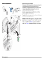
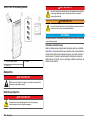
Remove the access cover
Remove the access cover to connect to the wiring terminals. Refer to
Figure 6.
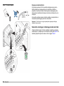
Figure 6 Access cover removal
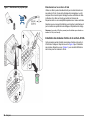
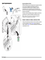
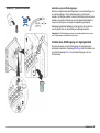
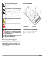
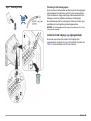
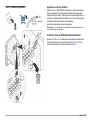
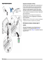
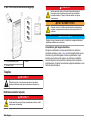
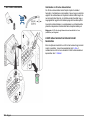
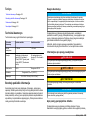
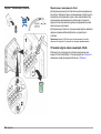
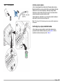
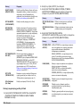
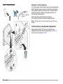
Connect optional devices
Install the cables for output or input devices as shown in Figure 7. Make
sure to use the wire gauge that is specified for the connection. Refer to
Specifications on page 3. To configure a device, refer to the operations
manual.
English
7

Figure 7 Device connection
Connect to the 4–20 mA outputs
Use twisted pair shielded wire for the 4–20 mA output connections.
Connect the shield at the recorder end or the analyzer end. Do not
connect the shield at both ends of the cable. Use of non-shielded cable
can result in radio frequency emission or susceptibility levels higher than
the allowed levels.
Refer to the installation manual to connect the device and for wiring and
load impedance specifications.
Note: The 4-20 mA outputs cannot be used to provide power to a 2-wire (loop-
powered) transmitter.
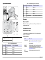
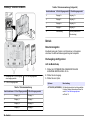
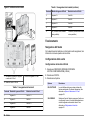
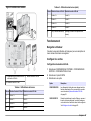
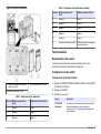
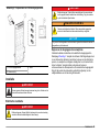
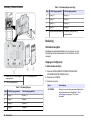
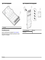
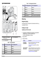
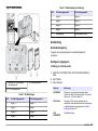
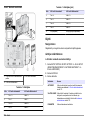
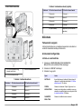
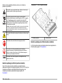
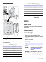
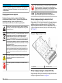
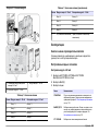
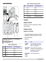
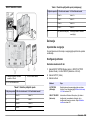
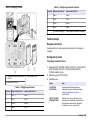
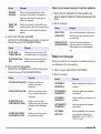
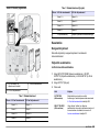
Install the 4–20 mA input and output module
Use this procedure to install the 4–20 mA input or output module in the
analyzer. Refer to Figure 8 for the module installation. Refer to Table 1
for the terminal assignments for the 4–20 mA modules.
8 English

Figure 8 Module installation
1 4–20 mA input or output module
location
3 4–20 mA input module
2 4–20 mA output module
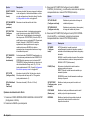
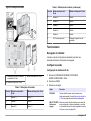
Table 1 Terminal assignments
Terminal 4–20 mA input module 4–20 mA output module
1 Input 1 + Output 1 +
2 Input 1 - Output 1 -
3 Input 2 + Output 2 +
4 Input 2 - Output 2 -
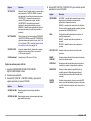
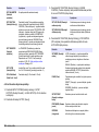
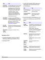
Table 1 Terminal assignments (continued)
Terminal 4–20 mA input module 4–20 mA output module
5 Input 3 + Output 3 +
6 Input 3 - Output 3 -
7 Input 4 + Output 4 +
8 Input 4 - Output 4 -
9 PE (Protective earth) Shield (Connected to protective earth)
Operation
User navigation
Refer to the analyzer operations manual for keypad description and
navigation information.
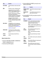
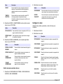
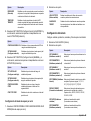
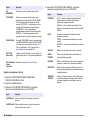
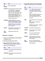
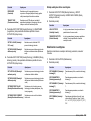
Configure the outputs
4–20 mA module setup
1. Select SETUP SYSTEM>SETUP OUTPUTS>4–20mA SETUP.
2. Select the OUTPUT.
3. Select an option.
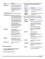
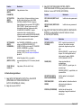
Option Description
ACTIVATION The menu list items change with the selected function.
Refer to 4–20 mA activation options on page 10 for
more information.
SELECT
SOURCE
Select the output. Options: None if the output is not
configured, the analyzer name or calculation if a
calculation formula has been configured. Refer to Set up
the calculation on page 11.
SET
PARAMETER
Select the measurement channel from the list.
English 9

Option Description
SET FUNCTION Select a function. Further options will vary depending on
which function is chosen. LINEAR CONTROL—Signal is
linearly dependent on the process value. PID
CONTROL—Signal works as a PID (Proportional,
Integral, Derivative) controller. LOGARITHMIC—Signal
is represented logarithmically within the process variable
range. BILINEAR—Signal is represented as two linear
segments within the process variable range.
SET TRANSFER If TRANSFER is or will be selected as the ERROR
HOLD MODE, select SET TRANSFER and enter the
transfer value. Range: 3.0 to 23.0 mA (default = 4.000).
Refer to Set the error hold mode on page 11.
SET FILTER Enter the filter value. This is a time-average filter value
of 0 to 120 seconds (default = 0).
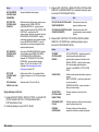
SCALE 0mA/4mA Select the scale (0–20 mA or 4–20 mA).
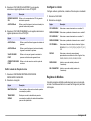
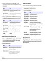
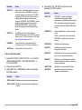
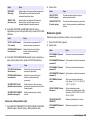
4–20 mA activation options
1. Select SETUP SYSTEM>SETUP OUTPUTS>4–20mA SETUP.
2. Select the applicable OUTPUT.
3. Select SET FUNCTION>LINEAR CONTROL and then select the
applicable options in the ACTIVATION menu.
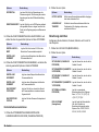
Option Description
SET LOW VALUE Sets the low endpoint of the process variable range.
SET HIGH VALUE Sets the high endpoint (upper value) of the process
variable range.
4. Select SET FUNCTION>PID CONTROL and then select the
applicable options in the ACTIVATION menu.
Option Description
SET MODE AUTO—the signal is automatically controlled by the
algorithm when the analyzer uses proportional, integral
and derivative inputs.
MANUAL—the signal is controlled by the user. To change
the signal manually, change the % value in MANUAL
OUTPUT.
PHASE Selects the signal result when process changes occur.
DIRECT—signal increases as the process increases.
REVERSE—signal increases as the process decreases.
SET SETPOINT Sets the value for a control point in the process.
PROP BAND Sets the value for the difference between the measured
signal and the necessary setpoint.
INTEGRAL Sets the period of time from the reagent injection point to
the contact with the measuring device.
DERIVATIVE Sets a value that adjusts for vacillation of the process. The
majority of applications can be controlled without the use
of the derivative setting.
TRANSIT TIME Sets the value to stop the PID control for a selected period
of time when the sample moves from the control pump to
the measurement sensor.
10 English

5. Select SET FUNCTION>LOGARITHMIC and then select the
applicable options in the ACTIVATION menu.
Option Description
SET 50% VALUE Sets the value corresponding to 50% of the process
variable range.
SET HIGH VALUE Sets the high endpoint (upper value) of the process
variable range.
6. Select SET FUNCTION>BILINEAR and then select the applicable
options in the ACTIVATION menu.
Option Description
SET LOW VALUE Sets the low endpoint of the process variable
range.
SET HIGH VALUE Sets the high endpoint (upper value) of the
process variable range.
SET KNEE POINT
VALUE
Sets the value at which the process variable
range divides into another linear segment.
SET KNEE POINT
CURRENT
Sets the value of the current at the knee point
value.
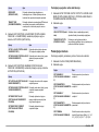
Set the error hold mode
1. Select SETUP SYSTEM>SETUP OUTPUTS>ERROR HOLD MODE.
2. Select an option.
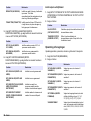
Option Description
HOLD OUTPUTS Holds the outputs at the last known value when
communications are lost.
TRANSFER
OUTPUTS
Switches to the transfer mode when communications
are lost. The outputs transfer to a pre-defined value.
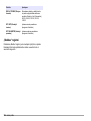
Set up the calculation
Set up variables, parameters, units and formulas for the analyzer.
1. Select CALCULATION.
2. Select an option.
Option Description
SET VARIABLE X Selects the sensor referring to the variable X.
SET PARAMETER X Selects the parameter referring to the variable X.
SET VARIABLE Y Selects the sensor referring to the variable Y.
SET PARAMETER Y Selects the parameter referring to the variable Y.
SET FORMULA Selects the calculation formula to complete. Options:
None, X-Y, X+Y, X/Y, [X/Y]%, [X+Y]/2, X*Y, [X-Y]%/X
DISPLAY FORMAT Selects the number of decimal places shown in a
calculation result. Options: Auto, XXXXX, XXXX.X,
XXX.XX, XX.XXX, X.XXXX
SET UNITS Enters the unit name (maximum of 5 characters).
SET PARAMETER Enters the measurement name (maximum of
5 characters).
Modbus registers
A list of Modbus registers is available for network communication. Refer
to www.hach.com or www.hach-lange.com for more information.
English 11

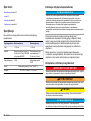
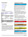
Inhaltsverzeichnis
Technische Daten auf Seite 12
Allgemeine Informationen auf Seite 12
Installation auf Seite 15
Betrieb auf Seite 18
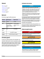
Technische Daten
Änderungen vorbehalten.
Technische Daten Eingangsmodul Ausgangsmodul
Stromaufnahme < 100 mA < 150 mA
Ausgänge Analog/Digital-Eingänge
(0-20 mA oder 4-20 mA),
Eingang oder
Digitaleingang
2 analoge Stromausgänge
(0–20 mA oder 4–20 mA)
Interner Widerstand 180 Ω max. 500 Ω
Anschlussklemme max. 2,5 mm
2
(AWG 11)
Abmessungen 23 mm x 100 mm x 115 mm (1 x 4 x 4.5 in.)
Allgemeine Informationen
Der Hersteller ist nicht verantwortlich für direkte, indirekte,
versehentliche oder Folgeschäden, die aus Fehlern oder
Unterlassungen in diesem Handbuch entstanden. Der Hersteller behält
sich jederzeit und ohne vorherige Ankündigung oder Verpflichtung das
Recht auf Verbesserungen an diesem Handbuch und den hierin
beschriebenen Produkten vor. Überarbeitete Ausgaben der
Bedienungsanleitung sind auf der Hersteller-Webseite erhältlich.
Sicherheitshinweise
H I N W E I S
Der Hersteller ist nicht für Schäden verantwortlich, die durch Fehlanwendung
oder Missbrauch dieses Produkts entstehen, einschließlich, aber ohne
Beschränkung auf direkte, zufällige oder Folgeschäden, und lehnt jegliche
Haftung im gesetzlich zulässigen Umfang ab. Der Benutzer ist selbst dafür
verantwortlich, schwerwiegende Anwendungsrisiken zu erkennen und
erforderliche Maßnahmen durchzuführen, um die Prozesse im Fall von möglichen
Gerätefehlern zu schützen.
Bitte lesen Sie dieses Handbuch komplett durch, bevor Sie dieses Gerät
auspacken, aufstellen oder bedienen. Beachten Sie alle Gefahren- und
Warnhinweise. Nichtbeachtung kann zu schweren Verletzungen des
Bedieners oder Schäden am Gerät führen.
Stellen Sie sicher, dass die durch dieses Messgerät bereitgestellte
Sicherheit nicht beeinträchtigt wird. Verwenden bzw. installieren Sie das
Messsystem nur wie in diesem Handbuch beschrieben.
Bedeutung von Gefahrenhinweisen
G E F A H R
Kennzeichnet eine mögliche oder drohende Gefahrensituation, die, wenn sie
nicht vermieden wird, zum Tod oder zu schweren Verletzungen führt.
W A R N U N G
Kennzeichnet eine mögliche oder drohende Gefahrensituation, die, wenn sie
nicht vermieden wird, zum Tod oder zu schweren Verletzungen führen kann.
V O R S I C H T
Kennzeichnet eine mögliche Gefahrensituation, die zu geringeren oder
moderaten Verletzungen führen kann.
H I N W E I S
Kennzeichnet eine Situation, die, wenn sie nicht vermieden wird, das Gerät
beschädigen kann. Informationen, die besonders beachtet werden müssen.
12 Deutsch

Warnhinweise
Lesen Sie alle am Gerät angebrachten Aufkleber und Hinweise.
Nichtbeachtung kann Verletzungen oder Beschädigungen des Geräts
zur Folge haben. Im Handbuch wird in Form von Warnhinweisen auf die
am Gerät angebrachten Symbole verwiesen.
Dieses Symbol am Gerät weist auf Betriebs- und/oder
Sicherheitsinformationen im Handbuch hin.
Elektrogeräte, die mit diesem Symbol gekennzeichnet sind, dürfen ab
12. August 2005 nicht in öffentlichen europäischen Abfallsystemen
entsorgt werden. Benutzer von Elektrogeräten müssen in Europa in
Einklang mit lokalen und nationalen europäischen Regelungen (EU-
Richtlinie 2002/96/EG) Altgeräte kostenfrei dem Hersteller zur
Entsorgung zurückgeben.
Hinweis: Mit der Wiederverwertung, der stofflichen Verwertung oder anderen
Formen der Verwertung von Altgeräten leisten Sie einen wichtigen Beitrag zum
Schutz unserer Umwelt.
Dieses Symbol weist auf die Gefahr eines elektrischen Schlages hin,
der tödlich sein kann.
Dieses Symbol kennzeichnet den Bedarf für einen Augenschutz.
Dieses Symbol weist darauf hin, dass das gekennzeichnete Teil an
einen Erdungsschutzleiter angeschlossen werden muss. Wenn das
Instrument nicht über einen Netzstecker an einem Kabel verfügt,
verbinden Sie die Schutzerde mit der Schutzleiterklemme.
Wenn sich dieses Symbol auf dem Produkt befindet, gibt es die
Position einer Sicherung oder eines Strombegrenzers an.
Produktübersicht (4-20 mA-Eingangsmodul)
Über das 4-20 mA-Eingangsmodul kann der Analysator externe digitale
und analoge Signale (0-20 mA/4-20 mA) empfangen. Bei
geschlossenem Überbrückungsschalter werden digitale, bei geöffnetem
Überbrückungsschalter analoge Signale empfangen. Siehe Abbildung 1.
Abbildung 1 4-20 mA-Eingangsmodul
1 Überbrückungsschalter 2 Klemmenblock
Produktübersicht (4-20 mA-Ausgangsmodul)
Das 4-20 mA-Ausgangsmodul stellt vier zusätzliche 4-20 mA-Ausgänge
für den Analysator bereit. Siehe Abbildung 2.
Deutsch 13

Abbildung 2 4–20-mA-Ausgangsmodul
1 Klemmenblock
Produktkomponenten
Stellen Sie sicher, dass Sie alle Teile erhalten haben. Siehe Abbildung 3
und Abbildung 4. Wenn Komponenten fehlen oder beschädigt sind,
kontaktieren Sie bitte den Hersteller oder Verkäufer.
Abbildung 3 Bauteile des 4-20 mA-Eingangsmoduls
1 4-20 mA-Eingangsmodul 3 Kennzeichnung
2 Schrauben (4x)
14 Deutsch

Abbildung 4 Bauteile des 4-20 mA-Ausgangsmoduls
1 4–20-mA-Ausgangsmodul 3 Kennzeichnung
2 Schrauben (4x)
Installation
G E F A H R
Mehrere Gefahren. Nur qualifiziertes Personal sollte die in diesem
Kapitel des Dokuments beschriebenen Aufgaben durchführen.
Elektrische Installation
G E F A H R
Lebensgefahr durch Stromschlag. Trennen Sie das Gerät immer von
der Spannungsversorgung, bevor Sie elektrische Anschlüsse
herstellen.
G E F A H R
Lebensgefahr durch Stromschlag. Verwenden Sie nur Anschlüsse mit
der angegebenen Umgebungsschutzart. Halten Sie sich an die
Anforderungen im Abschnitt mit den Spezifikationen.
W A R N U N G
Stromschlaggefahr. Extern angeschlossene Geräte müssen über eine
entsprechende Sicherheitsnormenbeurteilung des jeweiligen Landes
verfügen.
H I N W E I S
Achten Sie darauf, dass die Ausrüstung unter Einhaltung der lokalen, regionalen
und nationalen Vorschriften am Gerät angeschlossen wird.
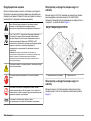
Ausbau der Zugangsstopfen
Installieren Sie die Kabel und Leitung durch die elektrischen Zugänge.
Siehe Abbildung 5. Entfernen Sie die Gummistopfen. Drücken Sie sie
dazu aus der Einfassung, um die Dichtung zu lösen, und ziehen Sie von
außen, um sie dann komplett zu entfernen. Entfernen Sie bei Bedarf mit
einem Hammer und Schraubenzieher die Vorprägungen aus der
elektrischen Zugangsplatte. Um die Schutzklasse des Geräts nicht zu
beeinträchtigen, verschließen Sie alle nicht verwendeten Anschlüsse mit
einer Abdeckung.
Deutsch 15

Abbildung 5 Elektrische Zugänge
1 Eingang Spannungsversorgung
(nur Netzkabel), keine Masseplatte.
Nicht für die Leitung verwenden.
3 Kommunikations- und
Netzwerkmodule (8x)
2 Kommunikations- und
Netzwerkmodule (3x)
4 Ein- oder Ausgang
Spannungsversorgung (Leitung
oder Netzkabel), Masseplatte,
Kommunikations- und
Netzwerkmodule (8x)
Ausbau der Schutzabdeckung
Bauen Sie die Schutzabdeckung aus, um die Verdrahtungsklemmen
anzuschließen. Siehe Abbildung 6.
Abbildung 6 Ausbau der Schutzabdeckung
Anschluss optionaler Geräte
Installieren Sie die Kabel für Ausgabe- oder Eingabegeräte; siehe
Abbildung 7. Achten Sie darauf, Leitungsquerschnitte zu verwenden, die
für den Anschluss spezifiziert sind. Siehe Technische Daten
auf Seite 12. Angaben zur Konfiguration der Geräte finden Sie in der
Bedienungsanleitung.
16
Deutsch

Abbildung 7 Anschluss von Geräten
Anschluss an die 4-20 mA-Ausgänge
Verwenden Sie geschirmtes Twisted-Pair-Kabel für den Anschluss an
die 4-20 mA-Ausgänge. Schließen Sie den Schirm am Recorder oder
Analysator an. Schließen Sie den Schirm NICHT an beiden Kabelenden
an! Die Verwendung ungeschirmter Kabel kann zu unzulässig hohen
Hochfrequenzemissionen oder Störempfindlichkeiten über das zulässige
Maß hinaus führen.
Angaben zum Anschluss des Geräts, zur Verdrahtung und zum
Lastwiderstand finden Sie im Installationshandbuch.
Hinweis: Die 4-20 mA-Ausgänge können nicht zur Durchleitung von Strom zu
einem 2-adrigen (schleifenbetriebenen) Sender verwendet werden.
Installation des 4-20 mA-Eingangs- und
Ausgangsmoduls
Verwenden Sie dieses Verfahren, um das 4-20 mA-Eingangs- und
Ausgangsmodul im Analysator zu installieren. Informationen zur
Installation des Moduls finden Sie unter Abbildung 8. Die
Klemmenbelegung für die 4-20 mA-Module finden Sie unter Tabelle 1.
Deutsch 17

Abbildung 8 Installation des Moduls
1 Einbaulage des 4-20 mA-Eingangs-
oder Ausgangsmoduls
3 4-20 mA-Eingangsmodul
2 4–20-mA-Ausgangsmodul
Tabelle 1 Klemmenzuordnung
Anschlussklemme 4-20 mA-Eingangsmodul 4–20-mA-Ausgangsmodul
1 Eingang 1 + Ausgang 1 +
2 Eingang 1 - Ausgang 1 -
3 Eingang 2 + Ausgang 2 +
4 Eingang 2 - Ausgang 2 -
Tabelle 1 Klemmenzuordnung (fortgesetzt)
Anschlussklemme 4-20 mA-Eingangsmodul 4–20-mA-Ausgangsmodul
5 Eingang 3 + Ausgang 3 +
6 Eingang 3 - Ausgang 3 -
7 Eingang 4 + Ausgang 4 +
8 Eingang 4 - Ausgang 4 -
9 Schutzerdung Schirm (verbunden mit
Schutzerdung)
Betrieb
Benutzernavigation
Eine Beschreibung der Tastatur und Informationen zur Navigation
entnehmen Sie bitte der Bedienungsanleitung des Analysators.
Die Ausgänge konfigurieren
4-20 mA-Modul Setup
1. Wählen Sie SYSTEMEINSTELLUNGEN>EINSTELLUNG
AUSGÄNGE>EINSTELLUNG 4-20 mA.
2. Wählen Sie den Ausgang.
3. Wählen Sie eine Option.
Optionen Beschreibung
ACTIVATION (AKTIVIEREN) Die Menüliste ändert sich mit der gewählten
Funktion. Weitere Informationen finden Sie
unter 4-20 mA-Aktivierungsoptionen
auf Seite 19.
18 Deutsch

Optionen Beschreibung
SIGNAL-QUELLE Wählen Sie den Ausgang. Optionen: Keine,
wenn der Ausgang nicht konfiguriert ist,
Analysator-Name oder Berechnung, wenn
eine Berechnungsformel konfiguriert wurde.
Siehe Berechnung einrichten
auf Seite 20.
PARAMETEREINSTELLUNG Wählen Sie den Messkanal aus der Liste.
FUNKTIONSEINSTELLUNG Wählen Sie eine Funktion aus. Weitere
Optionen hängen davon ab, welche Funktion
gewählt wird. LINEARE REGELUNG: Das
Signal ist linear vom Prozesswert abhängig.
PID-Regelung: Das Signal wird zur PID-
Regelung (Proportional, Integral, Differential)
verwendet. LOGARITHMISCH: Das Signal
wird innerhalb des Bereichs der
Prozessvariablen logarithmisch dargestellt.
BILINEAR: Das Signal wird innerhalb des
Bereichs der Prozessvariablen als zwei
lineare Segmente dargestellt.
ERSATZWERT Wenn ERSATZWERT als
FEHLERHALTEMODUS gewählt ist oder
gewählt werden soll, wählen Sie
ERSATZWERT, und geben Sie den
Ersatzwert ein. Bereich 3,0 bis 23,0 mA
(Standardwert: 4,000). Siehe Den
Fehlerhaltemodus definieren auf Seite 20.
DÄMPFUNG Geben Sie den Filterwert ein. Dies ist
zeitgewichteter Filterwert, der zwischen
0 und 120 Sekunden liegt (Standardwert: 0).
SKALA 0 mA/4 mA Wählen Sie die Skala (0-20 mA oder
4-20 mA).
4-20 mA-Aktivierungsoptionen
1. Wählen Sie SYSTEMEINSTELLUNGEN>EINSTELLUNG
AUSGÄNGE>EINSTELLUNG 4-20 mA.
2. Wählen Sie den gewünschten Ausgang.
3. Wählen Sie FUNKTIONSEINSTELLUNG>LINEARE REGELUNG,
und wählen Sie dann die gewünschte Optionen im Menü
AKTIVIEREN.
Optionen Beschreibung
EINSTELLUNG
UNTERWERT
Legt den unteren Endpunkt des Bereichs der
Prozessvariablen fest.
EINSTELLUNG
OBERWERT
Legt den oberen Endpunktwert des Bereichs der
Prozessvariablen fest.
4. Wählen Sie FUNKTIONSEINSTELLUNG>PID-REGELUNG, und
wählen Sie dann die gewünschte Optionen im Menü AKTIVIEREN.
Optionen Beschreibung
BETRIEBSART AUTO: Das Signal wird automatisch durch den
Algorithmus im Analysator gesteuert, wobei
Proportional-, Integral- und Differentialeingänge
verwendet werden.
MANUELL: Das Signal wird vom Benutzer
gesteuert. Um das Signal manuell zu ändern,
ändern Sie den %-Wert im MANUELLEN
AUSGANG.
RICHTUNG Wählt das Signalergebnis bei
Prozesswertänderungen aus.
DIREKT: Das Signal wird erhöht, wenn sich der
Prozesswert erhöht.
UMGEKEHRT: Das Signal wird erhöht, wenn sich
der Prozesswert reduziert.
SOLLWERT Legt den Wert für einen Regelungspunkt im
Prozess fest.
PROPORTIONAL Legt den Wert für den Unterschied zwischen dem
gemessenen Signal und dem erforderlichen
Sollwert fest.
INTEGRAL Legt die Zeitdauer vom Reagenzeinspritzpunkt bis
zum Kontakt mit dem Messgerät fest.
Deutsch 19

Optionen Beschreibung
DIFFERENTIAL Legt einen Wert fest, der Schwankungen des
Prozesses ausgleicht. Die Steuerung der meisten
Anwendungen kann ohne Differentialeinstellung
erfolgen.
ÜBERTRAGUNGSZEIT Legt den Wert fest, um die PID-Regelung während
einer gewählten Dauer zu stoppen, wenn sich die
Probe von der Regelungspumpe zum Messsensor
bewegt.
5. Wählen Sie FUNKTIONSEINSTELLUNG>LOGARITHMISCH, und
wählen Sie dann die gewünschte Optionen im Menü AKTIVIEREN.
Optionen Beschreibung
EINSTELLUNG 50 %-
WERT
Legt den Wert fest, der dem 50-%-Wert des
Bereichs der Prozessvariablen entspricht.
EINSTELLUNG
OBERWERT
Legt den oberen Endpunktwert des Bereichs der
Prozessvariablen fest.
6. Wählen Sie FUNKTIONSEINSTELLUNG>BILINEAR, und wählen Sie
dann die gewünschte Optionen im Menü AKTIVIEREN.
Optionen Beschreibung
EINSTELLUNG
UNTERWERT
Legt den unteren Endpunkt des Bereichs der
Prozessvariablen fest.
EINSTELLUNG
OBERWERT
Legt den oberen Endpunktwert des Bereichs
der Prozessvariablen fest.
KNICKPKTWERT
FESTLEGEN
Legt den Wert fest, an dem sich der Bereich
der Prozessvariablen in ein anderes lineares
Segment aufteilt.
KNICKPKTSTROM
FESTLEG.
Legt den Wert des Stroms am Knickpunktwert
fest.
Den Fehlerhaltemodus definieren
1. Wählen Sie SYSTEMEINSTELLUNGEN>EINSTELLUNG
AUSGÄNGE>ERROR HOLD MODE (FEHLERHALTEMODUS).
2. Wählen Sie eine Option.
Optionen Beschreibung
OUTPUT HALTEN Hält bei einem Kommunikationsausfall die Ausgänge
beim letzten bekannten Wert.
AUSGÄNGE AUF
TRANSFER
Schaltet bei einem Kommunikationsausfall in den
Transfermodus. Die Ausgänge nehmen einen
vordefinierten Wert an.
Berechnung einrichten
Konfigurieren Sie die Variablen, Parameter, Einheiten und Formeln für
den Analysator.
1. Wählen Sie CALCULATION (BERECHNUNG).
2. Wählen Sie eine Option.
Optionen Beschreibung
SET VARIABLE X (VARIABLE X
FESTLEGEN)
Legt den Sensor fest, der sich auf die
Variable X bezieht.
SET PARAMETER X (PARAMETER
X FESTLEGEN)
Legt den Sensor fest, der sich auf die
Variable X bezieht.
SET VARIABLE Y (VARIABLE Y
FESTLEGEN)
Legt den Sensor fest, der sich auf die
Variable Y bezieht.
SET PARAMETER Y (PARAMETER
Y FESTLEGEN)
Legt den Sensor fest, der sich auf die
Variable Y bezieht.
SET FORMULA (FORMEL
FESTLEGEN)
Legt die zu verwendende
Berechnungsformel fest. Optionen:
Keine, X–Y, X+Y, X/Y, [X/Y]%, [X
+Y]/2, X*Y, [X*Y]%/X
DISPLAY FORMAT
(Anzeigeformat)
Legt die Anzahl der Dezimalstellen
fest, die im Ergebnis von
Berechnungen angezeigt werden.
Optionen: Auto, XXXXX, XXXX.X,
XXX.XX, XX.XXX, X.XXXX
20 Deutsch
Pagina se încarcă...
Pagina se încarcă...
Pagina se încarcă...
Pagina se încarcă...
Pagina se încarcă...
Pagina se încarcă...
Pagina se încarcă...
Pagina se încarcă...
Pagina se încarcă...
Pagina se încarcă...
Pagina se încarcă...
Pagina se încarcă...
Pagina se încarcă...
Pagina se încarcă...
Pagina se încarcă...
Pagina se încarcă...
Pagina se încarcă...
Pagina se încarcă...
Pagina se încarcă...
Pagina se încarcă...
Pagina se încarcă...
Pagina se încarcă...
Pagina se încarcă...
Pagina se încarcă...
Pagina se încarcă...
Pagina se încarcă...
Pagina se încarcă...
Pagina se încarcă...
Pagina se încarcă...
Pagina se încarcă...
Pagina se încarcă...
Pagina se încarcă...
Pagina se încarcă...
Pagina se încarcă...
Pagina se încarcă...
Pagina se încarcă...
Pagina se încarcă...
Pagina se încarcă...
Pagina se încarcă...
Pagina se încarcă...
Pagina se încarcă...
Pagina se încarcă...
Pagina se încarcă...
Pagina se încarcă...
Pagina se încarcă...
Pagina se încarcă...
Pagina se încarcă...
Pagina se încarcă...
Pagina se încarcă...
Pagina se încarcă...
Pagina se încarcă...
Pagina se încarcă...
Pagina se încarcă...
Pagina se încarcă...
Pagina se încarcă...
Pagina se încarcă...
Pagina se încarcă...
Pagina se încarcă...
Pagina se încarcă...
Pagina se încarcă...
Pagina se încarcă...
Pagina se încarcă...
Pagina se încarcă...
Pagina se încarcă...
Pagina se încarcă...
Pagina se încarcă...
Pagina se încarcă...
Pagina se încarcă...
Pagina se încarcă...
Pagina se încarcă...
Pagina se încarcă...
Pagina se încarcă...
Pagina se încarcă...
Pagina se încarcă...
Pagina se încarcă...
Pagina se încarcă...
Pagina se încarcă...
Pagina se încarcă...
Pagina se încarcă...
Pagina se încarcă...
Pagina se încarcă...
Pagina se încarcă...
Pagina se încarcă...
Pagina se încarcă...
Pagina se încarcă...
Pagina se încarcă...
Pagina se încarcă...
Pagina se încarcă...
Pagina se încarcă...
Pagina se încarcă...
Pagina se încarcă...
Pagina se încarcă...
Pagina se încarcă...
Pagina se încarcă...
Pagina se încarcă...
Pagina se încarcă...
Pagina se încarcă...
Pagina se încarcă...
Pagina se încarcă...
Pagina se încarcă...
Pagina se încarcă...
Pagina se încarcă...
Pagina se încarcă...
Pagina se încarcă...
Pagina se încarcă...
Pagina se încarcă...
Pagina se încarcă...
Pagina se încarcă...
Pagina se încarcă...
Pagina se încarcă...
Pagina se încarcă...
Pagina se încarcă...
Pagina se încarcă...
Pagina se încarcă...
Pagina se încarcă...
Pagina se încarcă...
Pagina se încarcă...
Pagina se încarcă...
Pagina se încarcă...
Pagina se încarcă...
Pagina se încarcă...
Pagina se încarcă...
Pagina se încarcă...
Pagina se încarcă...
Pagina se încarcă...
Pagina se încarcă...
Pagina se încarcă...
Pagina se încarcă...
Pagina se încarcă...
Pagina se încarcă...
Pagina se încarcă...
Pagina se încarcă...
Pagina se încarcă...
Pagina se încarcă...
Pagina se încarcă...
Pagina se încarcă...
Pagina se încarcă...
Pagina se încarcă...
Pagina se încarcă...
Pagina se încarcă...
Pagina se încarcă...
Pagina se încarcă...
Pagina se încarcă...
Pagina se încarcă...
Pagina se încarcă...
Pagina se încarcă...
Pagina se încarcă...
Pagina se încarcă...
Pagina se încarcă...
Pagina se încarcă...
Pagina se încarcă...
Pagina se încarcă...
Pagina se încarcă...
Pagina se încarcă...
Pagina se încarcă...
Pagina se încarcă...
Pagina se încarcă...
Pagina se încarcă...
Pagina se încarcă...
Pagina se încarcă...
Pagina se încarcă...
Pagina se încarcă...
Pagina se încarcă...
Pagina se încarcă...
Pagina se încarcă...
Pagina se încarcă...
Pagina se încarcă...
Pagina se încarcă...
Pagina se încarcă...
Pagina se încarcă...
Pagina se încarcă...
Pagina se încarcă...
Pagina se încarcă...
Pagina se încarcă...
Pagina se încarcă...
Pagina se încarcă...
Pagina se încarcă...
Pagina se încarcă...
Pagina se încarcă...
Pagina se încarcă...
Pagina se încarcă...
Pagina se încarcă...
Pagina se încarcă...
Pagina se încarcă...
Pagina se încarcă...
Pagina se încarcă...
Pagina se încarcă...
Pagina se încarcă...
Pagina se încarcă...
Pagina se încarcă...
Pagina se încarcă...
Pagina se încarcă...
Pagina se încarcă...
Pagina se încarcă...
Pagina se încarcă...
Pagina se încarcă...
Pagina se încarcă...
Pagina se încarcă...
Pagina se încarcă...
Pagina se încarcă...
Pagina se încarcă...
Pagina se încarcă...
Pagina se încarcă...
Pagina se încarcă...
-
 1
1
-
 2
2
-
 3
3
-
 4
4
-
 5
5
-
 6
6
-
 7
7
-
 8
8
-
 9
9
-
 10
10
-
 11
11
-
 12
12
-
 13
13
-
 14
14
-
 15
15
-
 16
16
-
 17
17
-
 18
18
-
 19
19
-
 20
20
-
 21
21
-
 22
22
-
 23
23
-
 24
24
-
 25
25
-
 26
26
-
 27
27
-
 28
28
-
 29
29
-
 30
30
-
 31
31
-
 32
32
-
 33
33
-
 34
34
-
 35
35
-
 36
36
-
 37
37
-
 38
38
-
 39
39
-
 40
40
-
 41
41
-
 42
42
-
 43
43
-
 44
44
-
 45
45
-
 46
46
-
 47
47
-
 48
48
-
 49
49
-
 50
50
-
 51
51
-
 52
52
-
 53
53
-
 54
54
-
 55
55
-
 56
56
-
 57
57
-
 58
58
-
 59
59
-
 60
60
-
 61
61
-
 62
62
-
 63
63
-
 64
64
-
 65
65
-
 66
66
-
 67
67
-
 68
68
-
 69
69
-
 70
70
-
 71
71
-
 72
72
-
 73
73
-
 74
74
-
 75
75
-
 76
76
-
 77
77
-
 78
78
-
 79
79
-
 80
80
-
 81
81
-
 82
82
-
 83
83
-
 84
84
-
 85
85
-
 86
86
-
 87
87
-
 88
88
-
 89
89
-
 90
90
-
 91
91
-
 92
92
-
 93
93
-
 94
94
-
 95
95
-
 96
96
-
 97
97
-
 98
98
-
 99
99
-
 100
100
-
 101
101
-
 102
102
-
 103
103
-
 104
104
-
 105
105
-
 106
106
-
 107
107
-
 108
108
-
 109
109
-
 110
110
-
 111
111
-
 112
112
-
 113
113
-
 114
114
-
 115
115
-
 116
116
-
 117
117
-
 118
118
-
 119
119
-
 120
120
-
 121
121
-
 122
122
-
 123
123
-
 124
124
-
 125
125
-
 126
126
-
 127
127
-
 128
128
-
 129
129
-
 130
130
-
 131
131
-
 132
132
-
 133
133
-
 134
134
-
 135
135
-
 136
136
-
 137
137
-
 138
138
-
 139
139
-
 140
140
-
 141
141
-
 142
142
-
 143
143
-
 144
144
-
 145
145
-
 146
146
-
 147
147
-
 148
148
-
 149
149
-
 150
150
-
 151
151
-
 152
152
-
 153
153
-
 154
154
-
 155
155
-
 156
156
-
 157
157
-
 158
158
-
 159
159
-
 160
160
-
 161
161
-
 162
162
-
 163
163
-
 164
164
-
 165
165
-
 166
166
-
 167
167
-
 168
168
-
 169
169
-
 170
170
-
 171
171
-
 172
172
-
 173
173
-
 174
174
-
 175
175
-
 176
176
-
 177
177
-
 178
178
-
 179
179
-
 180
180
-
 181
181
-
 182
182
-
 183
183
-
 184
184
-
 185
185
-
 186
186
-
 187
187
-
 188
188
-
 189
189
-
 190
190
-
 191
191
-
 192
192
-
 193
193
-
 194
194
-
 195
195
-
 196
196
-
 197
197
-
 198
198
-
 199
199
-
 200
200
-
 201
201
-
 202
202
-
 203
203
-
 204
204
-
 205
205
-
 206
206
-
 207
207
-
 208
208
-
 209
209
-
 210
210
-
 211
211
-
 212
212
-
 213
213
-
 214
214
-
 215
215
-
 216
216
-
 217
217
-
 218
218
-
 219
219
-
 220
220
-
 221
221
-
 222
222
-
 223
223
-
 224
224


Hach Lange 4-20 mA Module Manual de utilizare
- Tip
- Manual de utilizare
în alte limbi
Lucrări înrudite
-
 Hach Polymetron 9611sc PO43-LR Instrucțiuni de utilizare
-
 Hach POLYMETRON 8810 ISE Basic User Manual
-
 Hach POLYMETRON 8810 ORP Basic User Manual
-
 Hach POLYMETRON 8810 ISE Basic User Manual
-
 Hach RTC111 Basic User Manual
-
 Hach Polymetron 9610sc Maintenance And Troubleshooting Manual
-
 Hach 9586sc Basic User Manual
-
Hach SC4200c User Instructions


