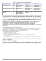
Hach ORBISPHERE 3658 Basic User Manual
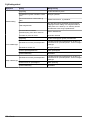
- Categorie
- Măsurare
- Tip
- Basic User Manual

DOC024.98.93008
ORBISPHERE Model
3658 Portable Analyzer
09/2018, Edition 9
Basic User Manual
Allgemeines Benutzerhandbuch
Manuale di base per l'utente
Manuel d'utilisation de base
Manual básico del usuario
Manual básico do utilizador
Grundlæggende brugervejledning
Allmän användarhandbok
Manual de utilizare de bază
Alapvető felhasználói kézikönyv

English..............................................................................................................................3
Deutsch.......................................................................................................................... 26
Italiano............................................................................................................................ 51
Français......................................................................................................................... 76
Español........................................................................................................................ 100
Português.................................................................................................................... 125
Dansk............................................................................................................................149
Svenska....................................................................................................................... 173
Română....................................................................................................................... 196
Magyar......................................................................................................................... 221
2

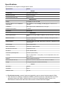
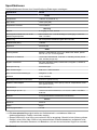
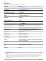
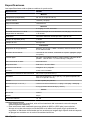
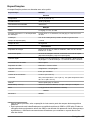
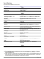
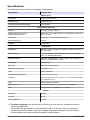
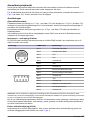
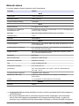
Specifications
Specifications are subject to change without notice.
Specification Details
Sample
Temperature -5 to 35°C (23 to 95°F)
Maximum pressure 10 bars (145 psia)
Recommended flow rate 150 mL/minute
Measurement
Range 0–10 g/kg, 0–4 V/V, 0–6 bar
Accuracy within ± 5°C of calibration
temperature
The greater of: ± 1% of reading; ± 0.025 g/kg or ± 0.012 V/V or ±
16 mbar
Calibration With High Precision Calibration Kit or CO
2
gas
Response time (90%) 1 minute
Cycle time 20 seconds
Instrument
Power requirements Batteries: two C-type, NiMH or alkaline, each 26 x 50 mm, 2.4–3 volts
total
Batteries life time 15 hours continuous use, 3 weeks in “standby” mode (power OFF,
standby purge ON)
Digital interface RS-232C: Baud rate=4800; Parity=None; Stop bit=1; Start bit=0; Flow
control=None
Data storage 500 measurements
EMC requirements EN61326-1: EMC Directive
1
Mechanical connectors Swagelock ¼ inch
Enclosure IP 65, stainless steel
Instrument operating limits 0 to 40°C (32 to 104°F)
Humidity 95% for temperature < 30°C (86°F); 70% for temperature 30 to 40°C
(86 to 104°F)
Altitude
2
2000 m (6560 ft) maximum
Dimensions (W x H x D) 130 mm x 210 mm x 220 mm; 5.11 in. x 8.27 in. x 8.66 in.
Weight 3.5 kg (including flow chamber and sensor)
Sensor
Membrane 29561A
Thickness 25 μm
Radiation limits 10
5
rad
1
For the best accuracy, prevent instrument operation near to external electromagnetic fields.
2
This instrument is rated for an altitude of 2000 m (6562 ft) maximum. Although the use of this
equipment above the 2000 m altitude does not show any substantial safety concern, the
manufacturer recommends that users with concerns contact technical support.
English 3

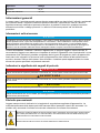
General information
In no event will the manufacturer be liable for direct, indirect, special, incidental or consequential
damages resulting from any defect or omission in this manual. The manufacturer reserves the right to
make changes in this manual and the products it describes at any time, without notice or obligation.
Revised editions are found on the manufacturer’s website.
Safety information
N O T I C E
The manufacturer is not responsible for any damages due to misapplication or misuse of this product including,
without limitation, direct, incidental and consequential damages, and disclaims such damages to the full extent
permitted under applicable law. The user is solely responsible to identify critical application risks and install
appropriate mechanisms to protect processes during a possible equipment malfunction.
Please read this entire manual before unpacking, setting up or operating this equipment. Pay
attention to all danger and caution statements. Failure to do so could result in serious injury to the
operator or damage to the equipment.
Make sure that the protection provided by this equipment is not impaired. Do not use or install this
equipment in any manner other than that specified in this manual.
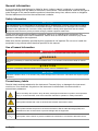
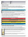
Use of hazard information
D A N G E R
Indicates a potentially or imminently hazardous situation which, if not avoided, will result in death or serious injury.
W A R N I N G
Indicates a potentially or imminently hazardous situation which, if not avoided, could result in death or serious
injury.
C A U T I O N
Indicates a potentially hazardous situation that may result in minor or moderate injury.
N O T I C E
Indicates a situation which, if not avoided, may cause damage to the instrument. Information that requires special
emphasis.
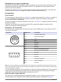
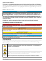
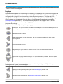
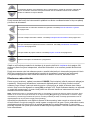
Precautionary labels
Read all labels and tags attached to the instrument. Personal injury or damage to the instrument
could occur if not observed. A symbol on the instrument is referenced in the manual with a
precautionary statement.
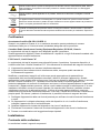
This is the safety alert symbol. Obey all safety messages that follow this symbol to avoid potential
injury. If on the instrument, refer to the instruction manual for operation or safety information.
This symbol indicates that a risk of electrical shock and/or electrocution exists.
This symbol indicates the presence of devices sensitive to Electro-static Discharge (ESD) and
indicates that care must be taken to prevent damage with the equipment.
This symbol, when noted on a product, indicates the instrument is connected to alternate current.
4 English

Electrical equipment marked with this symbol may not be disposed of in European domestic or
public disposal systems. Return old or end-of-life equipment to the manufacturer for disposal at no
charge to the user.
Products marked with this symbol indicates that the product contains toxic or hazardous substances
or elements. The number inside the symbol indicates the environmental protection use period in
years.
Certification
EN 55011/CISPR 11 Notification Warning
This is a Class A product. In a domestic environment this product may cause radio interference in
which case the user may be required to take adequate measures.
Canadian Radio Interference-Causing Equipment Regulation, IECS-003, Class A:
Supporting test records reside with the manufacturer.
This Class A digital apparatus meets all requirements of the Canadian Interference-Causing
Equipment Regulations.
Cet appareil numérique de classe A répond à toutes les exigences de la réglementation canadienne
sur les équipements provoquant des interférences.
FCC Part 15, Class "A" Limits
Supporting test records reside with the manufacturer. The device complies with Part 15 of the FCC
Rules. Operation is subject to the following conditions:
1. The equipment may not cause harmful interference.
2. The equipment must accept any interference received, including interference that may cause
undesired operation.
Changes or modifications to this equipment not expressly approved by the party responsible for
compliance could void the user's authority to operate the equipment. This equipment has been tested
and found to comply with the limits for a Class A digital device, pursuant to Part 15 of the FCC rules.
These limits are designed to provide reasonable protection against harmful interference when the
equipment is operated in a commercial environment. This equipment generates, uses and can
radiate radio frequency energy and, if not installed and used in accordance with the instruction
manual, may cause harmful interference to radio communications. Operation of this equipment in a
residential area is likely to cause harmful interference, in which case the user will be required to
correct the interference at their expense. The following techniques can be used to reduce
interference problems:
1. Disconnect the equipment from its power source to verify that it is or is not the source of the
interference.
2. If the equipment is connected to the same outlet as the device experiencing interference, connect
the equipment to a different outlet.
3. Move the equipment away from the device receiving the interference.
4. Reposition the receiving antenna for the device receiving the interference.
5. Try combinations of the above.
Installation
What you have received
You should have received the following major components:
• An instrument, model 3658/418R, with keypad, display, and handle
• A membrane-covered thermal conductivity (TC) sensor, model 31478
• A flow chamber, model 32058 with flow adjustment valve
English
5

• The Hach 3658 software on a CD and a PC communications cable
• Two C-type batteries
• A sensor recharge kit in a plastic case containing materials to maintain and service your sensor
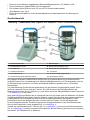
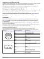
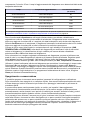
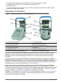
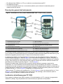
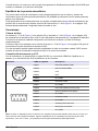
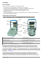
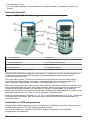
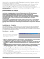
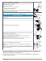
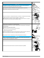
Instrument overview
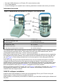
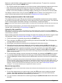
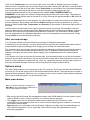
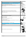
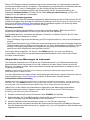
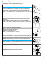
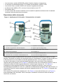
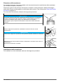
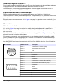
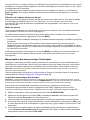
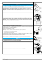
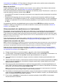
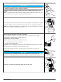
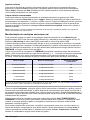
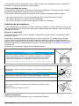
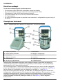
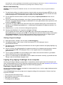
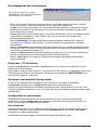
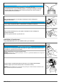
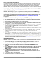
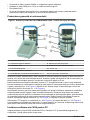
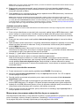
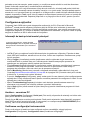
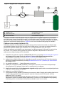
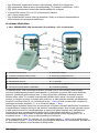
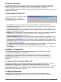
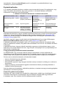
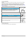
Figure 1 ORBISPHERE 3658 portable CO
2
analyzer - front and rear view
1 Sample flow inlet 7 Battery cap
2 Flow rate adjustment valve 8 Purge gas (air) inlet
3 Flow chamber 9 Flow chamber locking nut
4 Sample flow outlet 10 TC sensor
5 Pressure relief valve 11 Purge gas (air) outlet
6 RS-232 port and DC power connection 12 Sensor locking pin
The ORBISPHERE 3658 portable analyzer accurately measures carbon dioxide in dissolved phase,
using a thermal conductivity sensor. The analyzer can store up to 500 measurements, and its
rechargeable batteries allow up to 15 hours continuous operation.
Before each measurement the TC sensor is automatically flushed with ambient dried air supplied by
the integrated pump and condenser, and sucked into the flow chamber through the purge gas inlet
(No. 8 in Figure 1) before being released back into the atmosphere via the purge gas outlet (No.
11 in Figure 1).
After each purge, the gas to be measured diffuses from the liquid sample through the membrane,
changing the thermal conductivity of the gas surrounding the detector. As each gas has its own
specific thermal conductivity the measurement is not affected by the presence of other gases unlike
traditional total pressure/temperature methods. The liquid sample flow rate is adjustable using the
flow rate adjustment valve (No. 2 in Figure 1) integrated into the flow chamber.
Both the membrane-covered TC sensor (No. 10 in Figure 1) and the flow chamber (No. 3 in Figure 1)
are shipped pre-installed on the instrument. It will, however, be necessary to remove the flow
chamber when servicing the sensor.
3658 PC software installation
Install the Hach 3658 software by inserting the accompanying CD into your PC and running the
SetUp program. Simply follow the on-screen instructions.
When finished, a new directory HU\HU3658 is created on your hard disk containing the software and
help files.
6
English

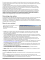
Atmospheric pressure equilibrium
As soon as you receive the instrument, it will be necessary to ensure the interior and exterior of the
instrument are both at the same atmospheric pressure. It is probable that during shipment these
pressures will become different.
To ensure the pressures are equal, simply press the pressure relief valve located on the top of the
instrument (No. 5 in Figure 1 on page 6) for about 5 seconds before releasing.
Connections
Flow chamber
The flow chamber’s sample inlet (N° 1 in Figure 1 on page 6) and outlet (N° 4 in Figure 1 on page 6)
use ¼-inch diameter transparent plastic tubing. Connect by compression fittings to the sample
source and to the drain, respectively.
Control the sample flow using the adjustment valve (No. 2 in Figure 1 on page 6) located on the front
of the flow chamber.
If ordered, you will also have received a model 32051 sample tube adapter to attach the flow
chamber inlet tubing to the sampling point.
Instrument - PC connection
An RS-232 cable is supplied with the instrument, with a 6-pin LEMO plug on one end and a 9-pin D-
Type plug on the other.
Connection LEMO-6 Pin Description
Pin 1 Transmitted data (TXD)
Pin 2 Received data (RXD)
Pin 3 CTS
Pin 4 RTS
Pin 5 Not used
Pin 6 Ground
Pin 1 Not used
Pin 2 RS-232 Transmitted Data (TXD)
Pin 3 RS-232 Received Data (RXD)
Pin 4 Not used
Pin 5 Ground
Pin 6 Not used
Pin 7 Request to send RTS
Pin 8 Clear to send RTS
Pin 9 Not used
Note: If you use an adapter for the connection to the PC, make sure it is designed for this purpose and, thus, has
all nine pins accessible. Some 25-to-9 pin adapters are supplied for specific use, such as a mouse, and these may
have only certain pins available.
It is not necessary to keep the PC connected to the instrument during measurement. This connection
is required for downloading stored measurements, real-time monitoring, reviewing and changing
configuration parameters and testing the instrument from the PC.
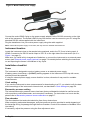
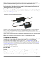
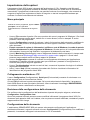
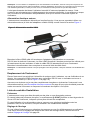
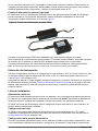
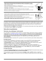
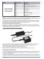
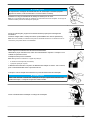
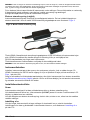
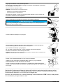
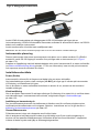
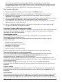
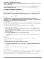
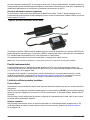
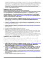
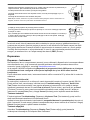
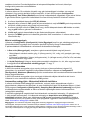
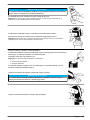
External power supply (optional)
The instrument is usually powered by the batteries supplied. You can, however, power it from an
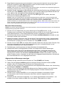
external power source using the model 32939 power supply adaptor as illustrated in Figure 2.
English
7

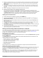
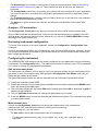
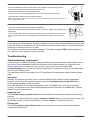
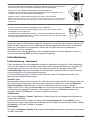
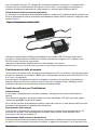
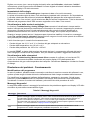
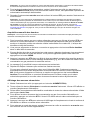
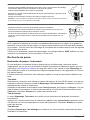
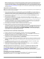
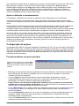
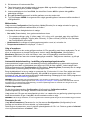
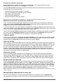
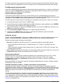
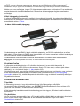
Figure 2 Model 32939 power supply
Connect the male LEMO-6 plug on the power supply adapter, to the RS-232 connector on the right
side of the instrument. The female LEMO-6 plug can then be used to connect to your PC using the
standard RS-232 cable supplied with the instrument.
Plug the transformer into your mains power supply using the cable supplied.
Note: If the external power supply is not clean, this may result in unstable measurements.
Instrument location
Locate the instrument close to the sample being analyzed, and to the PC if one is being used. A
LEMO-6 connector for RS-232 serial output to a PC is on the right side of the instrument (No. 6 in
Figure 1 on page 6).
Make sure you install a fully charged set of batteries, or connect the instrument to an external power
source (see External power supply (optional) on page 7 for details) before switching the instrument
on and exposing the sensor’s membrane to any liquid.
Installation checklist
Power
The instrument is designed to work on battery power or an external power supply.
If battery power should drop, a [LO BAT] warning appears in the instrument LCD's top left corner,
and they should be replaced.
If using an external power supply, ensure that this is clean, otherwise it may result in unstable
measurements.
Clock setting
If you use the instrument to store measurements for downloading to a PC, you should verify the date
and time settings of the instrument's internal clock, as described in Clock settings on page 24.
Barometric pressure setting
The internal barometric pressure sensor has been factory calibrated but should be verified on-site
with a precision certified barometer, and corrected if necessary. For instructions on how to do this,
please refer to Barometric pressure sensor calibration on page 17.
Flow chamber
The flow chamber inlet and outlet should be free of any obstructions.
When analyzing carbonated beverages, sufficient pressure must be provided to avoid degassing of
the beverage during its passage through the flow chamber. Check for the absence of bubbles in the
inlet tubing.
If necessary, adjust the pressure using the flow adjustment valve.
8
English

Operating Instructions
N O T I C E
To avoid damaging the sensor, never remove the flow chamber during normal operation. The flow chamber
should only be removed during service procedures.
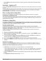
Operating controls
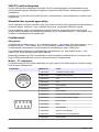
The front panel of the instrument has a three-digit liquid crystal display (LCD). The LCD includes a
right-side marker to distinguish between gas concentration and temperature display. This marker
also indicates the measurement display units (g/kg, V/V, etc.) depending on the instrument
configuration. To the LCD's right is a label showing the measurement units configured at the factory
for your application.
In addition to the controls indicated on the front panel, there is also a pressure relief valve on top of
the instrument. Refer to Instrument overview on page 6. This button need only be pressed as part of
the installation procedures, and/or if pressure builds up inside the instrument due to large
temperature changes.
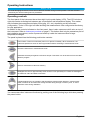
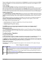
The panel keyboard has the following push-button controls:
Power switch. This turns instrument power on or places in standby. When switched on, the
instrument performs a series of start-up procedures before switching to measurement mode
Places the instrument in measurement mode
Calibrates the analyzer against a reference sample. This button can be locked out from the Hach
3658 PC program
Stores a measurement value into memory
Backlights the LCD for approximately three minutes. Push repeatedly to increase the backligth to
the maximum value and back to minimum.
Toggles between gas concentration and temperature measurement displays in measurement
mode, increases or decreases the storage number during storage or memory view, or sets a
calibration value during calibration
You can access other instrument functions by pushing one of the following keys while also pressing
the power button:
English
9

Selects dissolved or gaseous measurement phase. Refer to Gas measurement phase
on page 15.
Start automatic data acquisition. Refer to Automatic data acquisition on page 11.
Start memory storage view .Refer to Viewing stored measurements on page 12.
Starts continuous purge mode. Refer to Continuous purge on page 25.
Display program identification information
Once you have completed the installation and start-up procedures defined in Installation on page 5,
the analyzer can be operated independently, making measurements as a portable carbon dioxide
gas analyzer.
You may store these measurement values for later analysis via the Hach 3658 program (on your
personal computer) or the memory view mode (on the instrument). The Hach 3658 program
operation is described in detail throughout the manual, where relevant.
Taking measurements
To start the analyzer, press the POWER switch (located bottom left of the keyboard). When you turn
power on, the instrument displays the software version number briefly, and then starts a series of
start-up tests. This process should take only a few minutes, during which time a [tSt] message is
displayed on the LCD. Once the tests are completed, a clearing message [---] is displayed for a
further sixty seconds before the instrument switches automatically to measurement mode.
Note: The start-up tests will be repeated until successful, or for a maximum of 15 minutes. If the tests are still
unsuccessful after 15 minutes, a [Err] message will be displayed and the instrument locked. Turn the instrument off
and retry the start-up procedures, but if the problem persists, please contact your local Hach Lange service
representative for assistance.
Measurement updates are displayed every 20 seconds, and it is normal for the right-most digits to
vary in reaction to slight variations in gas content. For accurate measurements, the sensor's
membrane must be at the same temperature as the sample to be analyzed. If this not the case, allow
some sample to pass through the flow chamber for about 3 minutes before taking any
measurements.
The LCD includes a right-side marker to distinguish between gas concentration measurements and
temperature. This marker also indicates the measurement display units (k/kg, V/V, etc. depending on
the instrument configuration).
To switch between gas measurement and temperature measurement, press the Up/Down Arrow
buttons. To illuminate the LCD for approximately three minutes, press the Backlight button.
Select gas measurement phase
Ensure the gas measurement phase is correct for this measurement. For details on viewing the
current setting, refer to Reviewing instrument configuration on page 15. For details on changing
this setting, refer to Gas measurement phase on page 15.
Measurement mode
You can set the measurement mode to normal or maximum. For details on how to do this refer to
Measurement mode on page 17.
10
English

Maximum mode facilitates making measurements in bottles and cans. To search for a maximum
measurement value, press the MEAS button.
• The LCD first shows the message [run] for a few seconds, before displaying measurement values.
• After a 60 second measurement cycle, the instrument searches for two consecutive gas
measurements with less than 2% difference. When this condition occurs, the displayed value
freezes on the LCD (indicated by a blinking display), allowing you to note down or store the data.
The display remains frozen until you press the MEAS button to make a new measurement, or you
select normal measurement mode (as described in Measurement mode on page 17).
Storing measurements in the instrument
The analyzer will store up to 500 gas concentration and temperature measurement values, labeled
by numbers 0 through 499, along with the current date and time of each measurement. You have the
choice of acquiring this information manually or automatically, as described below.
Note: Do not put the instrument into standby while it is in the process of storing data, otherwise the data values will
be lost.
Before storing measurements, you should verify the date and time settings of the instrument's
internal clock, as described in Clock settings on page 24.
Automatic data acquisition
Note: When the instrument is used to automatically store measurement data, all buttons except the POWER key
are disabled. If enough time elapses to store all 500 values, the instrument will return to normal measurement mode
and the buttons re-enabled.
Before starting automatic measurement storage, first select the sampling rate desired using the Hach
3658 program. Refer to Automatic data acquisition - Setting sampling intervals on page 16.
1. Put the instrument into standby (by pressing the POWER key).
2. Then hold down the STO button while switching the instrument back ON. The LCD displays the
message Sto for about one second.
3. Normal gas concentration measurements are displayed for about two minutes.
4. After two minutes the instrument displays the sample number (starting at 000), then the gas
concentration measurement value followed by [- - -] to indicate the measurement is being stored.
5. This storage sequence repeats automatically, at the rate specified by the Hach 3658 program
Sampling Rate menu. Values are stored sequentially in sample numbers 000 through 499.
Note: If you have not cleared previously stored values, the storage sequence automatically overwrites the older
values, as they are stored.
6. To end automatic storage, put the instrument into standby (by pressing the POWER key) while it
is in normal measurement mode and not while it is in the process of automatically storing data.
7. Switching ON again without holding down the STO button returns the instrument to measurement
mode.
Note: If you accidentally interrupt the automatic data storage by switching off the instrument while it is in the
process of storing a value, and you then attempt to download the stored values by the Hach 3658 program, you
will get a Windows Checksum Error message, and you will not be able to view the measurement data. If this
happens, go back to the instrument and manually log one more value. Refer to Manual data acquisition
on page 11. You can then download your original set of values to your PC.
Manual data acquisition
Note: You cannot store measurement data manually if the instrument has already been set up to store the data
automatically.
1. For the first measurement you wish to store, press the STO button once to display a sample
number. The default sample number is 000 (for first time access), or the last used memory
position where data was stored, incremented by a value of 1.
2. You can increase or decrease this number by pressing the Up/Down Arrow buttons within three
seconds.
English
11

3. Should you decide at this point, not to store this particular measurement, just wait five seconds
and the display returns to measurement mode. You may also exit this routine by pressing the
MEAS button.
4. Press STO a second time, within five seconds of the first. The instrument then displays a brief
clearing [- - -] message, followed by the gas concentration measurement value for about three
seconds.
5. The [- - -] message is displayed as this measurement value is stored.
6. Repeat the above steps to store additional measurements.
If you stored the first value as sample 001, the instrument automatically increases the next
storage location, and labels it sample 002. You can increase or decrease this number by pressing
the Up/Down Arrow buttons. If you label a sample number the same as a previously stored
measurement value, the new measurement value overwrites the previously stored value.
Viewing stored measurements
1. Put the instrument into standby (by pressing the POWER key).
2. Hold down the Up Arrow button while switching the instrument back ON. The LCD displays a
sample location number.
3. Scroll through the numbered sample locations of all the stored values using the Up Arrow and
Down Arrow buttons.
4. To view the actual gas concentration measurement value at a particular sample number, press
the STO button. The LCD now displays the stored value for that sample number.
5. Press STO a second time to return to the next numbered location display, to continue scrolling or
view another stored value.
6. To return to the measurement mode, put the instrument into standby and then back ON again
without holding down any additional buttons.
Storing and accessing measurements from a computer
If you have made measurements and stored them in the analyzer, you should be ready to bring them
into the Hach 3658 program for viewing, copying, saving and printing. Refer to Options setup
on page 14 for additional information on the Hach 3658 program.
Downloading stored values
To download the stored results from the instrument to the PC, choose the DownLoad data command
from the Logger menu.
The DownLoad window presents a display of the stored measurements from the instrument. The
window displays five columns of data:
• Sample (sequence number of the sample)
• Conc (concentration of the measured gas)
• Date (date of the measurement)
• Time (time of the measurement)
• Sample Description
The descriptions can be modified for your applications using the procedures described below.
Altering the sampling point descriptions
For help in identifying the locations of various sampling points that are stored by the instrument, you
may choose the Sampling Point Description command from the Logger menu to bring up the
dialog box.
The measurement values to be placed in positions 0 through 499 can be described however you
wish. Double-click on a particular position (or click Modify), then type a description in the box.
Choose OK when finished entering a description.
12
English

When you Close this box, your modifications will be saved, and will appear in the Sample
Description column for the next downloaded list. These descriptions can be modified again later as
your requirements change.
Copying values
To copy the results to the Windows Clipboard, so that the data can be pasted into a spreadsheet,
word processor or other Windows program that accepts tabular text information, choose the
Clipboard command from the Export menu.
Saving values
To save this list of measurements as a text (.txt) file, capable of being recalled by the Hach 3658
program or imported as a file into other Windows programs, choose the Save As command from the
File menu. A dialog box appears, with a space to fill in with an eight-letter name (the program
automatically attaches a .txt suffix to these files). If you have saved previous files, a grayed-out list of
these names appears as well. Typical to Windows programs, Directories and Drives boxes can be
used to locate other storage devices on which to save your data.
Printing values
To place this list of measurements into a tabular format and send it to the Windows printer, choose
the Print command from the File menu. The program asks you to enter Title and Author
information. Note that the Date is fixed by your operating system. The resulting printed list will
include this information on each page.
Clearing stored values
To clear all the values stored in the analyzer via the Hach 3658 program, choose the Clear Data
command from the Logger menu. Since this action will clear the storage memory of the instrument, a
warning appears first. Choose OK to bring up the next dialog box to confirm the clear action. Choose
Clear to start the memory clear operation. A message, Reset should be completed appears in this
box when the task is finished.
Note: You can accomplish the same thing passively, by simply allowing the analyzer to overwrite a set of stored
values with new ones.
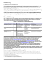
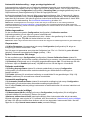
Monitoring measurements in real-time
You may wish to analyze a particular sampling point via the Hach 3658 program's Monitoring menu.
To use this Monitoring chart, the instrument must be connected to your PC. Choose Monitoring from
the Hach 3658 menu to bring up a chart display.
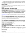
The Monitoring chart shows the gas concentration (in blue), temperature (in red), and pressure (in
green) as the sample is being measured by the instrument. The chart is updated directly from
instrument measurements, at a rate determined by the time scale set in the TIMEBASE box at the
lower right corner of the chart.
Click the TIMEBASE up/down pointers to change the time scale of the divisions of the chart. Each
division mark along the baseline (1, 2, ...10) can be made to represent from 30 seconds to 2½ hours,
providing from 5 minutes to 25 hours of continuously displayed samples. The chart updating rate is
determined by the time scale selected.
Timebase Updating rate* Maximum samples
(10 divisions)
30 Seconds/Division 5 Seconds/Sample 60
1 Minute/Division 5 Seconds/Sample 120
10 Minutes/Division 5 Seconds/Sample 1,200
30 Minutes/Division 9 Seconds/Sample 2,000
1 Hour/Division 18 Seconds/Sample 2,000
2.5 Hours/Division 45 Seconds/Sample 2,000
*This chart's updating rate is independent from the acquisition rate. Refer to Automatic data acquisition - Setting
sampling intervals on page 16.
English 13

Click on the Continuous box, in the lower right corner, to enable or disable continuous charting.
When this box is checked, the chart scrolls continuously after reaching the 10 division, and the oldest
samples are lost off the left of the chart. When Continuous is not checked, the chart stops displaying
new results after reaching the 10 division, and all subsequent measurements are lost.
Click the up/down pointers for each measurement variable (GAS, TEMPERATURE and
PRESSURE) at the right of the chart to change the scaling of that value on the chart. The display of
each measurement variable may be turned on or off by choosing the appropriate On or Off switch at
the right of the chart.
If your measurements do not chart properly, try using a higher or lower value scale or time base than
the one displayed. Adjust these scale factors before starting the monitoring operation. A running
display of latest sample Gas, Temperature and Pressure is also shown in the bottom-right corner of
the chart.
Use the buttons at the bottom of the chart to control real-time monitoring. Choose Go to clear the
chart and start real-time monitoring display, Stop to stop real-time monitoring and Copy to copy the
data from the chart as text information to the Windows Clipboard. This information can be pasted
from the clipboard into any Windows application, such as a spreadsheet or word processor. Finally,
choose Close to close the Monitoring window.
After use and storage
You can power off the instrument without losing setup or calibration parameters.
If measuring in a liquid sample, run clean warm water through the flow chamber after each series of
measurements to prevent passages from clogging, and to keep the membrane clean.
The sensor must be continuously purged to prevent any damage to the thermal conductivity sensing
element. The instrument handles this automatically, even if switched off during short periods (for
example overnight), provided it has a power supply (fully charged batteries or an external power
supply).
If you expect not to use your sensor for several days, flush all sample liquid out of the flow chamber,
remove it and dry with a soft tissue. Dry the sensor head surface with a clean soft tissue to ensure no
liquid is on the membrane or protection cap. Once dry, replace the sensor’s storage cap to protect it
from any accidental damage. Store with a silica bag to prevent any humidity build-up.
Options setup
The Hach 3658 program is an integral part of the CO
2
analyzer. Running under Microsoft Windows
®
,
it permits you to list and analyze up to 500 stored measurement values. The program also includes a
special monitoring feature, which lets your computer act as a chart recorder, and enables a hardware
test to ensure that the system is in good working order.
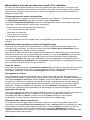
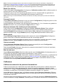
Main menu basics
When you start the program, it displays the
Main Menu, which automatically maximizes on
opening and appears as follows:
•
File serves typical Windows file management needs. Hach 3658 data files can be opened, saved
under a different name, closed, or printed. You can also exit the program.
• The Logger menu lets you download measurement values from the instrument, make
modifications to the sample list that can be used to identify sampling point locations, or clear the
instrument's stored values.
• Export places your information into the Windows Clipboard, so that it can be pasted directly into
other Windows programs. This is especially useful when working with spreadsheet or word
processing programs.
14
English

• The Monitoring menu creates a running chart of real-time measurements. Refer to Monitoring
measurements in real-time on page 13. These values can also be saved to the Windows
Clipboard.
• The Configuration menu lets you see how your system has been configured for your application.
You may use this menu to change the configuration parameters should your application needs
change.
• The Troubleshooting menu includes a series of tests, allows you to set the clock, and enables a
barometric pressure calibration routine.
• The Help menu gives access to the Help file and allows the identification of the Hach 3658
program.
Analyzer - PC connection
The Configuration, Serial port menu lets you choose one of four serial communication ports.
Click on OK to activate the selected port. If the port you have selected here is available, the Hach
3658 program will return to the main menu. Otherwise, you will see an RS232 ERRORS message
advising you to select another port.
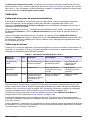
Reviewing instrument configuration
To review if the analyzer is set up as expected, choose the Configuration, Configuration view
command.
Some of the parameters listed, can be changed by using the Hach 3658 program. However, should
you see any unexpected items listed on your screen which you cannot correct, please contact your
Hach Lange representative.
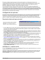
Configuring the instrument
The ORBISPHERE 3658 analyzer can be readily configured for your application using the following
commands in the Configuration menu. The instrument must be connected to your PC and powered
on, in order to change any configuration parameters.
Gas measurement phase
The instrument can measure CO
2
in either a liquid or a gaseous sample, but you must select which
gas phase to use. Choosing the Hach 3658 program's Configuration, Gas Phase menu lets you
select the gas measurement phase.
The gas measurement phase can also be selected from the instrument keyboard as follows:
1. Switch the instrument power OFF.
2. Switch the instrument on by holding down the CAL button and then pressing the POWER button
while still pressing the CAL button.
3. The instrument display will first show PHA before switching to either dIS for dissolved or gAS for
gaseous measurements.
4. Use the Up/Down Arrow buttons to change the gas phase to your choice.
5. Press the MEAS button to save the selected gas measurement phase. The instrument then goes
to measurement mode.
Measurement units
Choose the Configuration, Units menu to select gas measurement units, temperature
measurement units, and the liquid medium in which you are measuring.
Using this dialog box, you can select:
• The Gas units in which gas concentrations are to be displayed
• For dissolved measurements: g/kg, % (by weight), V/V, cc/kg, mL/L, ppm/ppb, ppm or
mg/100mL
English
15

• For gaseous measurements: %/ppm (by volume), % (by volume), kPa/Pa, kPa, bar/mbar, bar,
bar20/mbar20 or bar20
• The Liquid medium for dissolved gas concentration measurements: Water, Beer, Cola or Wine
• The Temperature units for display: °C or °F
Membrane selection
Membrane 29561A is the only membrane valid for CO
2
gas measurement with this analyzer. To
ensure the analyzer is correctly configured, choose Configuration, Membrane to bring up the box
which reveals the membrane models available.
Membrane 29561A should be the only membrane available for selection. Select this membrane and
click on OK.
Automatic data acquisition - Setting sampling intervals
The instrument can perform as a standalone data acquisition device, automatically recording gas
measurements with the date and time, and storing up to 500 of these values. Choosing the Hach
3658 program's Configuration, Sampling Rate menu lets you select time intervals (acquisition rate)
for this storage capability.
Use the slide bar to view and select a sampling rate, from 15 seconds to 1 hour. The selected rate is
shown in the Acquisition rate window. Click OK to save this rate. Once your choice is made, the
instrument can be used independently of the Hach 3658 program for data acquisition. Refer to
Automatic data acquisition on page 11.
Note: The Acquisition rate set via this menu is independent from the monitoring chart updating rate in Monitoring
measurements in real-time on page 13. The sampling rate menu applies only to automatic data acquisition, while
the chart updating rate is used only for displaying real-time results via the monitoring chart.
Calibration medium
You can use the Configuration, Calibration medium command to select how the sensor is to be
calibrated.
Choose either in pure CO
2
gas at atmospheric pressure or in a liquid or gaseous solution at a known
concentration of gas. Choose OK when the desired medium is selected.
Note: Hach Lange recommends the use of its High Precision Calibration Kits for the sensor calibration process.
Wine parameters
Choose Wine Parameters from the Configuration menu to provide a correction for the alcohol and
sugar content of the wine.
This sets two parameters that influence the solubility of CO
2
in wine. This is the degrees of Alcohol
in the wine, and the concentration of Sugar, in °Brix.
Locking out the instrument’s CAL button
You can use the Configuration, Sensor Calibration Status menu to prevent an accidental sensor
recalibration from the instrument keyboard.
Choose Disabled to lock out the keyboard CAL button. To unlock this capability, choose Enabled.
Choose OK when the desired mode is selected.
Rolling average
Choose Rolling Average Status from the Configuration menu to enable or disable the averaging of
gas concentration measurements.
To enable averaging on three successive gas measurements, choose Enable. Choose Disable to
disable rolling average.
Automatic shutdown
Choose Automatic Shutdown Status from the Configuration menu to activate the Automatic
Shutdown feature.
If you select Enable, the instrument switches off automatically after 10 minutes of inactivity, thereby
economizing battery power.
16
English

Measurement mode
Choose Measurement Mode from the Configuration menu to enable maximum measurement
mode for sampling in bottles and cans.
In Maximum measurement mode, the instrument searches for two consecutive measurements with
less than a 2% difference, as also described in Measurement mode on page 10. When this occurs,
the display is frozen and you may store the data. The instrument remains in this mode until you
select Normal measurement mode.
Calibration
Barometric pressure sensor calibration
You must have access to an accurate barometer to calibrate the instrument's internal barometric
pressure sensor. This is done using the Hach 3658 program on the PC. Choose Troubleshooting,
Pressure Calibration and a message will warn you that the current calibration will be lost.
Choose OK to continue. The calibration procedure then displays a Pressure Calibration dialog box.
The Measured Pressure value shows the current instrument pressure reading.
Enter the current atmospheric pressure, in mbars, in the Calibration Pressure entry box. Choose
Calibrate to direct the instrument to read and display the Measured Pressure using this calibration
value. Choose Quit when you are satisfied with the pressure calibration to return to normal
operation.
Sensor calibration
The TC sensor can be calibrated in a liquid sample with a known concentration of dissolved CO
2
, or
in pure CO
2
gas at atmospheric or elevated pressure. The following table gives information regarding
the different methods.
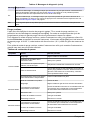
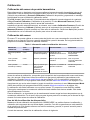
Table 1 Sensor calibration information
Calibration Method Time Benefits Drawbacks Reference
Liquid CO
2
solution 5 min High accuracy (for liquid
analysis)
Sensor linearity
validation not possible
ORBISPHERE High
Precision Calibration Kit
Gas at atmospheric
pressure
5 min Quick and easy Less accurate than
other methods
Gas with known purity,
certified barometer
Gas at elevated
pressure (2-3 bar)
10 min Higher accuracy than
atmospheric method.
Validation of the sensor
linearity
Requires a certified
pressure gauge
Certified pressure gauge
Before calibrating check that the sensor membrane surface is tight, smooth and wrinkle free. Select
the gas measurement phase for calibration (for full details see Gas measurement phase on page 15).
Next, select the calibration medium using the Hach 3658 program (see Calibration medium
on page 16).
Ensure that normal measurement mode is selected in the Measurement Mode menu of the Hach
3658 program (see Measurement mode on page 17).
Calibration must only be carried out once the TC sensor is giving a stable measurement. Expose the
membrane to the calibration sample until this stable reading is obtained. This usually takes about
5 minutes.
For calibration it is important that the sensor's membrane is at the same temperature as the
calibration sample. Therefore, allow some sample to pass through the flow chamber for 3 minutes
before calibrating.
Using the high precision calibration kit
Using the ORBISPHERE High Precision Calibration Kit, calibration and validation of the instrument
can be carried out quickly and easily. This ensures that each measurement of dissolved CO
2
gives a
true and accurate reading which is essential to final product quality.
English
17

In short these calibration kits offer:
• Traceable and accurate calibration
• Quick and easy solution preparation
• Eliminates handling of aggressive chemicals which are usually required in reference preparation
• High and low level kits are available to ensure accuracy in the appropriate measurement range
Once the solution has been prepared in the calibration bottle, it can be used in the standard package
piercer in place of the sample package.
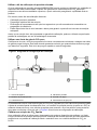
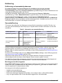
Using a source of pure CO
2
gas
Ensure that the purge cycle is running correctly by placing the purge gas exit tubing into water. This
rate should be more than four bubbles during the purge which lasts for 4 seconds. This purge cycle is
repeated every 20 seconds.
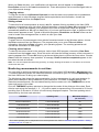
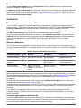
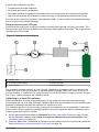
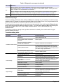
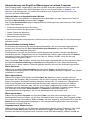
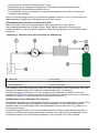
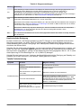
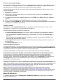
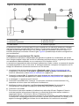
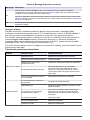
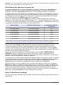
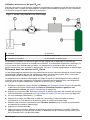
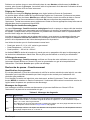
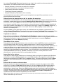
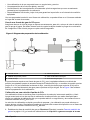
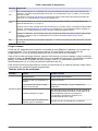
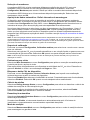
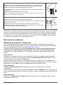
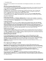
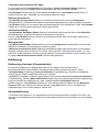
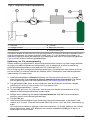
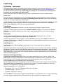
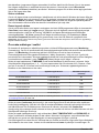
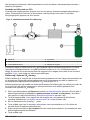
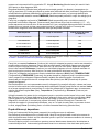
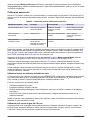
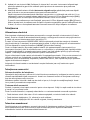
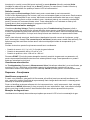
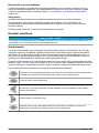
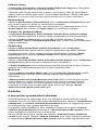
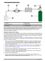
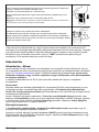
Figure 3 Calibration setup diagram
1 Needle valve 4 Pressure valve
2 Accurate pressure gauge 5 Beaker of water
3 Flow chamber 6 Pure gas supply
The procedure requires a source of pure CO
2
gas (regulated by a pressure valve) connected to the
central entry port of the flow chamber, an accurate pressure gauge (better than ± 2%) at the exit of
the flow chamber, a needle valve to control the flow on exit, and a beaker of water to monitor the gas
flow. Figure 3 above illustrates the calibration setup.
Calibrating in a liquid CO
2
solution
Effective calibration is critical to the performance of any analytical instrument, and Hach Lange
recommends the use of its High Precision Calibration Kits which are designed to give a traceable and
trustworthy calibration standard with defined CO
2
content of ± 0.5%.
The calibration solution is quick and easy to prepare, and calibration can be undertaken in less than
three minutes. Simply replace the package sample in your piercing device with the calibration bottle
containing the dissolved CO
2
solution.
1. Set the gas measurement phase to Dissolved (see Gas measurement phase on page 15) and
set the calibration medium to In a liquid or a gaseous sample at known concentration (see
Calibration medium on page 16).
2. Press the CAL button. Remember, this button may have been locked out to prevent an accidental
reset (see Locking out the instrument’s CAL button on page 16).
18
English

3. A brief clearing [---] message appears.
4. Press CAL again within a 3 second period. The instrument then displays the concentration of
CO
2
based on the last value of the calibration coefficient.
5. Modify this reading using the Up/Down Arrow keys until the displayed concentration agrees with
that of the calibration solution.
6. Press CAL again.
7. Start the flow of the standard (calibration) solution through the flow chamber. Adjust the flow until
the liquid is foam-free. The flow rate should be a minimum of 150 mL/min. (50% on the
32311 Flow Meter) and stable.
If the instrument makes two consecutive measurements with less than 1% difference, it calibrates
against this stabilized value. The LCD then displays the message [CAL] to indicate calibration
has been successfully completed.
If the calibration does not complete, the LCD displays the message [Err]. The reason for this
calibration error is either that the measured gas partial pressure is under 5 mbar, or that a wrong
instrument key was pressed during the calibration steps.
Note: A flow rate lower that 150 mL/min can be used for the calibration, but you must ensure that all
measurements made after the calibration are made at exactly the same flow rate as that used for the
calibration. For accurate results it is recommended to use a model 32311 Flow Meter set at 50% for the
optimum flow rate of 150mL/min. at room temperature (25°C).
Calibration in CO
2
at atmospheric pressure
The sensor can be calibrated in pure CO
2
gas at atmospheric pressure.
To ensure that the flow chamber and sensor components are dry, remove and blow dry the flow
chamber. Dry the sensor head surface with a clean soft tissue.
The analyzer uses an internal barometric pressure sensor during this calibration. First check that the
pressure sensor is correct and does not need recalibrating. If it does need to be recalibrated then
follow the instructions in Barometric pressure sensor calibration on page 17 before attempting this
calibration.
1. Set the gas measurement phase to Gaseous (see Gas measurement phase on page 15) and set
the calibration medium to In measured pure gas at atmospheric pressure (see Calibration
medium on page 16).
2. Connect a source of pure CO
2
gas to the inlet of the flow chamber, as illustrated in Figure 3
on page 18, and adjust the gas flow to one bubble per second when the exit tube is immersed in
water.
3. Press the CAL button. Remember, this button may have been locked out to prevent an accidental
reset (see Locking out the instrument’s CAL button on page 16).
4. brief clearing message [---] appears.
5. Press CAL again within a 3 second period.
If the instrument makes two consecutive measurements with less than 1% difference, it calibrates
against this stabilized value. The LCD then displays the message [CAL] to indicate calibration
has been successfully completed
If the calibration does not complete, the LCD displays the message [Err]. The reason for this
calibration error is either that the measured gas partial pressure is under 5 mbar, or that a wrong
instrument key was pressed during the calibration steps.
Calibration in CO
2
at elevated pressure
The sensor can be calibrated in pure CO
2
gas at an elevated pressure. This method requires an
accurate pressure gauge connected to the exit of the flow chamber.
When calibrating in gas phase, the flow chamber and sensor head must be dry. To ensure that the
flow chamber and sensor components are dry, remove and dry them with a clean soft tissue.
English
19

1. Set the gas measurement phase to Gaseous (see Gas measurement phase on page 15) and set
the calibration medium to In a liquid or a gaseous sample at known concentration (see
Calibration medium on page 16).
2. Connect a source of pure CO
2
gas to the inlet of the flow chamber, as illustrated in Figure 3
on page 18, and adjust the gas flow exiting from the flow chamber to be in the range of 1 to 5 bar
(it is best to use a pressure close to the application conditions).
3. Press the CAL button. Remember, this button may have been locked out to prevent an accidental
reset (see Locking out the instrument’s CAL button on page 16).
4. A brief clearing message [---] appears.
5. Press CAL again within a 3 second period. The instrument then displays the absolute pressure of
calibration gas (i.e. gauge pressure plus atmospheric pressure).
6. Modify this reading using the Up/Down Arrow keys until the displayed pressure agrees with that
of the gauge plus atmospheric pressure.
If the instrument makes two consecutive measurements with less than 1% difference, it calibrates
against this stabilized value. The LCD then displays the message [CAL] to indicate calibration
has been successfully completed.
If the calibration does not complete, the LCD displays the message [Err]. The reason for this
calibration error is either that the measured gas partial pressure is under 5 mbar, or that a wrong
instrument key was pressed during the calibration steps.
Maintenance
Power supply
It is important to maintain power to the instrument at all times, (either batteries or an external power
supply) to ensure the sensor is continually purged and so prevent damage to the TC sensor chip.
If the ORBISPHERE 3658 instrument is operating on battery power (two standard C-type cells), and
the battery power should drop, a [LO BAT] warning message is displayed in the instrument LCD's
top left corner.
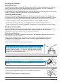
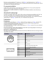
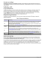
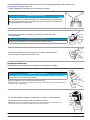
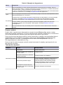
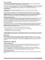
To install the batteries, unscrew the battery cap (on the right side of the instrument) with the tool
provided in the recharge kit, or with a coin or flat bladed screwdriver. Place the cells lengthwise into
the battery compartment (positive end first), and then replace the cap. Refer to the diagram on the
back of the instrument.
Rechargeable nickel-cadmium batteries may be used. Expect about 15 hours of autonomy in
continuous operational use, or 3 weeks in standby. Alkaline batteries provide the longest continuous
use though mercury-free batteries are available that present less of a disposal problem.
Make sure that a fully charged (or fresh) set of batteries is installed before switching on the
instrument.
Sensor maintenance
Maintenance schedule
Sensor maintenance includes membrane replacement and external cleaning to restore the original
sensor sensitivity. This means low running costs and down time reduced to a minimum.
The membrane needs to be replaced once or twice a year depending on application conditions. This
can be tailored accordingly.
Testing the sensor condition
Periodically, visually inspect the sensor head for any deposits. Rinse it under clean tap water, and
dry with a clean tissue.
To verify the sensor, check measurements against a known standard sample value:
• If reading deviation is ±1% of the expected value, no action needs to be taken.
• If deviation exceeds ± 1%, perform a new calibration.
• If deviation exceeds 10% of the original values, replace the membrane.
20
English
Pagina se încarcă...
Pagina se încarcă...
Pagina se încarcă...
Pagina se încarcă...
Pagina se încarcă...
Pagina se încarcă...
Pagina se încarcă...
Pagina se încarcă...
Pagina se încarcă...
Pagina se încarcă...
Pagina se încarcă...
Pagina se încarcă...
Pagina se încarcă...
Pagina se încarcă...
Pagina se încarcă...
Pagina se încarcă...
Pagina se încarcă...
Pagina se încarcă...
Pagina se încarcă...
Pagina se încarcă...
Pagina se încarcă...
Pagina se încarcă...
Pagina se încarcă...
Pagina se încarcă...
Pagina se încarcă...
Pagina se încarcă...
Pagina se încarcă...
Pagina se încarcă...
Pagina se încarcă...
Pagina se încarcă...
Pagina se încarcă...
Pagina se încarcă...
Pagina se încarcă...
Pagina se încarcă...
Pagina se încarcă...
Pagina se încarcă...
Pagina se încarcă...
Pagina se încarcă...
Pagina se încarcă...
Pagina se încarcă...
Pagina se încarcă...
Pagina se încarcă...
Pagina se încarcă...
Pagina se încarcă...
Pagina se încarcă...
Pagina se încarcă...
Pagina se încarcă...
Pagina se încarcă...
Pagina se încarcă...
Pagina se încarcă...
Pagina se încarcă...
Pagina se încarcă...
Pagina se încarcă...
Pagina se încarcă...
Pagina se încarcă...
Pagina se încarcă...
Pagina se încarcă...
Pagina se încarcă...
Pagina se încarcă...
Pagina se încarcă...
Pagina se încarcă...
Pagina se încarcă...
Pagina se încarcă...
Pagina se încarcă...
Pagina se încarcă...
Pagina se încarcă...
Pagina se încarcă...
Pagina se încarcă...
Pagina se încarcă...
Pagina se încarcă...
Pagina se încarcă...
Pagina se încarcă...
Pagina se încarcă...
Pagina se încarcă...
Pagina se încarcă...
Pagina se încarcă...
Pagina se încarcă...
Pagina se încarcă...
Pagina se încarcă...
Pagina se încarcă...
Pagina se încarcă...
Pagina se încarcă...
Pagina se încarcă...
Pagina se încarcă...
Pagina se încarcă...
Pagina se încarcă...
Pagina se încarcă...
Pagina se încarcă...
Pagina se încarcă...
Pagina se încarcă...
Pagina se încarcă...
Pagina se încarcă...
Pagina se încarcă...
Pagina se încarcă...
Pagina se încarcă...
Pagina se încarcă...
Pagina se încarcă...
Pagina se încarcă...
Pagina se încarcă...
Pagina se încarcă...
Pagina se încarcă...
Pagina se încarcă...
Pagina se încarcă...
Pagina se încarcă...
Pagina se încarcă...
Pagina se încarcă...
Pagina se încarcă...
Pagina se încarcă...
Pagina se încarcă...
Pagina se încarcă...
Pagina se încarcă...
Pagina se încarcă...
Pagina se încarcă...
Pagina se încarcă...
Pagina se încarcă...
Pagina se încarcă...
Pagina se încarcă...
Pagina se încarcă...
Pagina se încarcă...
Pagina se încarcă...
Pagina se încarcă...
Pagina se încarcă...
Pagina se încarcă...
Pagina se încarcă...
Pagina se încarcă...
Pagina se încarcă...
Pagina se încarcă...
Pagina se încarcă...
Pagina se încarcă...
Pagina se încarcă...
Pagina se încarcă...
Pagina se încarcă...
Pagina se încarcă...
Pagina se încarcă...
Pagina se încarcă...
Pagina se încarcă...
Pagina se încarcă...
Pagina se încarcă...
Pagina se încarcă...
Pagina se încarcă...
Pagina se încarcă...
Pagina se încarcă...
Pagina se încarcă...
Pagina se încarcă...
Pagina se încarcă...
Pagina se încarcă...
Pagina se încarcă...
Pagina se încarcă...
Pagina se încarcă...
Pagina se încarcă...
Pagina se încarcă...
Pagina se încarcă...
Pagina se încarcă...
Pagina se încarcă...
Pagina se încarcă...
Pagina se încarcă...
Pagina se încarcă...
Pagina se încarcă...
Pagina se încarcă...
Pagina se încarcă...
Pagina se încarcă...
Pagina se încarcă...
Pagina se încarcă...
Pagina se încarcă...
Pagina se încarcă...
Pagina se încarcă...
Pagina se încarcă...
Pagina se încarcă...
Pagina se încarcă...
Pagina se încarcă...
Pagina se încarcă...
Pagina se încarcă...
Pagina se încarcă...
Pagina se încarcă...
Pagina se încarcă...
Pagina se încarcă...
Pagina se încarcă...
Pagina se încarcă...
Pagina se încarcă...
Pagina se încarcă...
Pagina se încarcă...
Pagina se încarcă...
Pagina se încarcă...
Pagina se încarcă...
Pagina se încarcă...
Pagina se încarcă...
Pagina se încarcă...
Pagina se încarcă...
Pagina se încarcă...
Pagina se încarcă...
Pagina se încarcă...
Pagina se încarcă...
Pagina se încarcă...
Pagina se încarcă...
Pagina se încarcă...
Pagina se încarcă...
Pagina se încarcă...
Pagina se încarcă...
Pagina se încarcă...
Pagina se încarcă...
Pagina se încarcă...
Pagina se încarcă...
Pagina se încarcă...
Pagina se încarcă...
Pagina se încarcă...
Pagina se încarcă...
Pagina se încarcă...
Pagina se încarcă...
Pagina se încarcă...
Pagina se încarcă...
Pagina se încarcă...
Pagina se încarcă...
Pagina se încarcă...
Pagina se încarcă...
Pagina se încarcă...
Pagina se încarcă...
Pagina se încarcă...
Pagina se încarcă...
Pagina se încarcă...
Pagina se încarcă...
Pagina se încarcă...
Pagina se încarcă...
Pagina se încarcă...
Pagina se încarcă...
Pagina se încarcă...
Pagina se încarcă...
Pagina se încarcă...
Pagina se încarcă...
-
 1
1
-
 2
2
-
 3
3
-
 4
4
-
 5
5
-
 6
6
-
 7
7
-
 8
8
-
 9
9
-
 10
10
-
 11
11
-
 12
12
-
 13
13
-
 14
14
-
 15
15
-
 16
16
-
 17
17
-
 18
18
-
 19
19
-
 20
20
-
 21
21
-
 22
22
-
 23
23
-
 24
24
-
 25
25
-
 26
26
-
 27
27
-
 28
28
-
 29
29
-
 30
30
-
 31
31
-
 32
32
-
 33
33
-
 34
34
-
 35
35
-
 36
36
-
 37
37
-
 38
38
-
 39
39
-
 40
40
-
 41
41
-
 42
42
-
 43
43
-
 44
44
-
 45
45
-
 46
46
-
 47
47
-
 48
48
-
 49
49
-
 50
50
-
 51
51
-
 52
52
-
 53
53
-
 54
54
-
 55
55
-
 56
56
-
 57
57
-
 58
58
-
 59
59
-
 60
60
-
 61
61
-
 62
62
-
 63
63
-
 64
64
-
 65
65
-
 66
66
-
 67
67
-
 68
68
-
 69
69
-
 70
70
-
 71
71
-
 72
72
-
 73
73
-
 74
74
-
 75
75
-
 76
76
-
 77
77
-
 78
78
-
 79
79
-
 80
80
-
 81
81
-
 82
82
-
 83
83
-
 84
84
-
 85
85
-
 86
86
-
 87
87
-
 88
88
-
 89
89
-
 90
90
-
 91
91
-
 92
92
-
 93
93
-
 94
94
-
 95
95
-
 96
96
-
 97
97
-
 98
98
-
 99
99
-
 100
100
-
 101
101
-
 102
102
-
 103
103
-
 104
104
-
 105
105
-
 106
106
-
 107
107
-
 108
108
-
 109
109
-
 110
110
-
 111
111
-
 112
112
-
 113
113
-
 114
114
-
 115
115
-
 116
116
-
 117
117
-
 118
118
-
 119
119
-
 120
120
-
 121
121
-
 122
122
-
 123
123
-
 124
124
-
 125
125
-
 126
126
-
 127
127
-
 128
128
-
 129
129
-
 130
130
-
 131
131
-
 132
132
-
 133
133
-
 134
134
-
 135
135
-
 136
136
-
 137
137
-
 138
138
-
 139
139
-
 140
140
-
 141
141
-
 142
142
-
 143
143
-
 144
144
-
 145
145
-
 146
146
-
 147
147
-
 148
148
-
 149
149
-
 150
150
-
 151
151
-
 152
152
-
 153
153
-
 154
154
-
 155
155
-
 156
156
-
 157
157
-
 158
158
-
 159
159
-
 160
160
-
 161
161
-
 162
162
-
 163
163
-
 164
164
-
 165
165
-
 166
166
-
 167
167
-
 168
168
-
 169
169
-
 170
170
-
 171
171
-
 172
172
-
 173
173
-
 174
174
-
 175
175
-
 176
176
-
 177
177
-
 178
178
-
 179
179
-
 180
180
-
 181
181
-
 182
182
-
 183
183
-
 184
184
-
 185
185
-
 186
186
-
 187
187
-
 188
188
-
 189
189
-
 190
190
-
 191
191
-
 192
192
-
 193
193
-
 194
194
-
 195
195
-
 196
196
-
 197
197
-
 198
198
-
 199
199
-
 200
200
-
 201
201
-
 202
202
-
 203
203
-
 204
204
-
 205
205
-
 206
206
-
 207
207
-
 208
208
-
 209
209
-
 210
210
-
 211
211
-
 212
212
-
 213
213
-
 214
214
-
 215
215
-
 216
216
-
 217
217
-
 218
218
-
 219
219
-
 220
220
-
 221
221
-
 222
222
-
 223
223
-
 224
224
-
 225
225
-
 226
226
-
 227
227
-
 228
228
-
 229
229
-
 230
230
-
 231
231
-
 232
232
-
 233
233
-
 234
234
-
 235
235
-
 236
236
-
 237
237
-
 238
238
-
 239
239
-
 240
240
-
 241
241
-
 242
242
-
 243
243
-
 244
244
-
 245
245
-
 246
246
-
 247
247
-
 248
248


Hach ORBISPHERE 3658 Basic User Manual
- Categorie
- Măsurare
- Tip
- Basic User Manual
în alte limbi
- français: Hach ORBISPHERE 3658
- English: Hach ORBISPHERE 3658
- Deutsch: Hach ORBISPHERE 3658
- italiano: Hach ORBISPHERE 3658
- español: Hach ORBISPHERE 3658
- svenska: Hach ORBISPHERE 3658
- dansk: Hach ORBISPHERE 3658
- português: Hach ORBISPHERE 3658
Lucrări înrudite
-
 Hach ORBISPHERE 31285TC Basic User Manual
-
 Hach Lange ORBISPHERE 3100 Basic User Manual
-
Hach HQ440d Basic User Manual
-
 Hach Lange ORBISPHERE 3100 Basic User Manual
-
 Hach Polymetron 9610sc SiO2 Ghid de instalare
-
 Hach ORBISPHERE K1200 Basic User Manual
-
 Hach POLYMETRON 8810 ISE Basic User Manual
-
 Hach ORBISPHERE 31 series Basic User Manual
-
 Hach POLYMETRON 8810 ISE Basic User Manual
-
Hach sensION+ MM150 Manual de utilizare


Alte documente
-
Hama 00186434 Air Quality Detector Manualul proprietarului
-
Promate TimeBase-2 Manualul utilizatorului
-
Dräger Pac 7000 Instructions For Use Manual
-
Laserliner CoatingTest-Master Instrucțiuni de utilizare
-
Gigabyte GB-BACE-3150 Manualul proprietarului
-
Vonroc MM501DC Moisture Meter Manual de utilizare
-
CHAUVIN ARNOUX CA 8345 Ghid de inițiere rapidă
-
Weller WXR 3 Manual de utilizare
-
TESTBOY 72 Manual de utilizare
-
Megger PD Scan Manual de utilizare