Grundfos CU 241 Installation And Operating Instructions Manual
- Tip
- Installation And Operating Instructions Manual

CU 241
Single pump unit
Installation and operating instructions
CU 241 single pump unit
Installation and operating instructions
Other languages
http://net.grundfos.com/qr/i/99381579
GRUNDFOS INSTRUCTIONS


CU 241
English (GB)
Installation and operating instructions ..........................................................5
Български (BG)
Упътване за монтаж и експлоатация.........................................................19
Čeština (CZ)
Montážní a provozní návod .................................................................34
Deutsch (DE)
Montage- und Betriebsanleitung .............................................................48
Dansk (DK)
Monterings- og driftsinstruktion ..............................................................62
Eesti (EE)
Paigaldus- ja kasutusjuhend ................................................................76
Español (ES)
Instrucciones de instalación y funcionamiento ...................................................90
Suomi (FI)
Asennus- ja käyttöohjeet ..................................................................105
Français (FR)
Notice d'installation et de fonctionnement .....................................................119
Ελληνικά (GR)
Οδηγίες εγκατάστασης και λειτουργίας........................................................133
Hrvatski (HR)
Montažne i pogonske upute ................................................................148
Magyar (HU)
Telepítési és üzemeltetési utasítás...........................................................162
Italiano (IT)
Istruzioni di installazione e funzionamento .....................................................176
Lietuviškai (LT)
Įrengimo ir naudojimo instrukcija ............................................................190
Latviešu (LV)
Uzstādīšanas un ekspluatācijas instrukcija ....................................................204
Nederlands (NL)
Installatie- en bedieningsinstructies ..........................................................218
Polski (PL)
Instrukcja montażu i eksploatacji ............................................................232
Português (PT)
Instruções de instalação e funcionamento .....................................................246
Română (RO)
Instrucţiuni de instalare şi utilizare ...........................................................260
Srpski (RS)
Uputstvo za instalaciju i rad ................................................................274
Русский (RU)
Паспорт, Руководство по монтажу и эксплуатации.............................................288
Svenska (SE)
Monterings- och driftsinstruktion.............................................................303
Slovensko (SI)
Navodila za montažo in obratovanje .........................................................317
Türkçe (TR)
3
Table of contents

Montaj ve kullanım kılavuzu ................................................................331
Українська (UA)
Інструкції з монтажу та експлуатації ........................................................345
中文 (CN)
安装和使用说明书 .......................................................................360
(AR)
......................................................................372
4 CU 241
Table of contents

English (GB) Installation and operating instructions
Original installation and operating instructions
Table of contents
1. General information ........................5
1.1 Hazard statements..........................5
1.2 Notes ..................................5
2. Installing the product .......................6
2.1 Location ................................6
2.2 Mechanical installation .......................6
2.3 Electrical connection.........................7
3. Starting up the product ......................7
3.1 Connecting to Grundfos GO Remote...............7
3.2 Startup wizard on Grundfos GO Remote ............7
3.3 Startup wizard on the operating panel ..............7
3.4 How to enable Bluetooth on the operating panel........8
3.5 How to disable Bluetooth on the operating panel .......8
3.6 Testing the product..........................8
4. Product introduction........................8
4.1 Product description .........................8
4.2 Intended use .............................8
4.3 Features ................................8
4.4 Application types ...........................8
4.5 Terminals ...............................9
4.6 Identification..............................9
4.7 Supported communication interface modules and
protocols ................................9
5. Control functions .........................10
5.1 Operating panel ..........................10
6. Setting the product........................10
6.1 Setting the application type with Grundfos GO Remote. ..10
6.2 Setting the sensor type ......................10
6.3 Setting the start level .......................10
6.4 Setting the stop level .......................11
6.5 Setting the high level .......................11
6.6 After-run delay, high level.....................11
6.7 Stop delay ..............................11
6.8 Power-on delay...........................11
6.9 Dry-running protection.......................11
6.10 Using the same level switch for the start and stop level ..11
6.11 Antiseizing..............................11
6.12 Signal-detection time .......................12
6.13 Setting the maximum number of restarts with Grundfos
GO Remote .............................12
6.14 Setting the service interval with Grundfos GO Remote . ..12
6.15 Motor protection ..........................12
6.16 Alarm reset .............................12
6.17 Setting the buzzer with Grundfos GO Remote ........13
6.18 Setting units for Grundfos GO Remote.............13
6.19 Setting units for the operating panel with Grundfos GO
Remote................................13
6.20 GENIbus ...............................13
6.21 Security ...............................13
6.22 Starting the startup wizard with the operating panel .....13
7. Operating the product......................13
7.1 Manual operation..........................13
8. Servicing the product ......................14
8.1 Updating the product software..................14
8.2 Replacing the control unit.....................14
8.3 Replacing the CIM module ....................14
8.4 Replacing the battery .......................14
9. Fault finding the product ....................15
9.1 Overview of alarm and warning codes .............15
9.2 Code 2 (Power phase missing) .................15
9.3 Code 4 (Too many motor restarts) ...............15
9.4 Code 9 (Power phase sequence wrong)............15
9.5 Code 12 (Service needed) ....................15
9.6 Code 22 (Moisture in motor of pump) .............15
9.7 Code 25 (Wrong configuration) .................15
9.8 Code 48 (Motor is overloaded) .................16
9.9 Code 57 (Missing water in the application) ..........16
9.10 Code 69 (Winding temperature too high) ...........16
9.11 Code 84 (Memory storage media faulty)............16
9.12 Code 117 (Door opened) .....................16
9.13 Code 157 (Real-time clock monitoring) ............16
9.14 Code 159 (Communication error CIMxxx) ...........16
9.15 Code 165 (Signal fault) ......................16
9.16 Code 181 (Signal fault, PTC input) ...............17
9.17 Code 191 (High water level) ...................17
9.18 Code 205 (Level switch inconsistency) ............17
9.19 Code 225 (Communication error pump module) .......17
9.20 Code 226 (Communication error IO module) .........17
9.21 Code 229 (Water on floor) ....................17
10. Technical data ...........................17
11. Disposing of the product ....................18
1. General information
Read this document before you install the product.
Installation and operation must comply with local
regulations and accepted codes of good practice.
1.1 Hazard statements
The symbols and hazard statements below may appear in Grundfos
installation and operating instructions, safety instructions and
service instructions.
DANGER
Indicates a hazardous situation which, if not avoided, will
result in death or serious personal injury.
WARNING
Indicates a hazardous situation which, if not avoided,
could result in death or serious personal injury.
CAUTION
Indicates a hazardous situation which, if not avoided,
could result in minor or moderate personal injury.
The hazard statements are structured in the following way:
SIGNAL WORD
Description of the hazard
Consequence of ignoring the warning
• Action to avoid the hazard.
1.2 Notes
The symbols and notes below may appear in Grundfos installation
and operating instructions, safety instructions and service
instructions.
Observe these instructions for explosion-proof products.
A blue or grey circle with a white graphical symbol
indicates that an action must be taken.
A red or grey circle with a diagonal bar, possibly with a
black graphical symbol, indicates that an action must not
be taken or must be stopped.
If these instructions are not observed, it may result in
malfunction or damage to the equipment.
5
English (GB)

Tips and advice that make the work easier.
2. Installing the product
2.1 Location
Install the product in a location that meets the following
requirements:
• Place the product in a flood-safe place.
• Make sure that the ambient temperature is within the limits.
• Install the product as close as possible to the connected
pumps, sensors, and accessories.
• The product must be protected from direct sunlight.
• The product must be easily accessible.
• We recommend that you install the product in a protective shed
or enclosure to avoid direct sunlight and rain.
• Indoor installation: The product must be installed in a well-
ventilated room to ensure cooling of its components.
2.2 Mechanical installation
2.2.1 Mounting the control unit
1. Fasten the control unit with the four screws (1), M4 x 12,
supplied with the unit. Torque value: 0.5 Nm.
1
160.5 (6.3")
110.5 (4.35")
Min. 1 (0.04")
Max. 5 (0.2")
TM072345
Mounting the control unit
Related information
8.2 Replacing the control unit
2.2.2
Installing a communication interface module
You can fit a communication interface module (CIM) in the control
unit to enable communication with external systems. The module is
optional and is not delivered with the product. See the installation
and operating instruction for the module regarding electrical
connections.
Use an antistatic service kit when handling electronic
components. This prevents static electricity from
damaging the components.
1. Remove the screw in the back cover of the CU product.
TM071905
2. Remove the back cover.
TM071906
3. Break off the tap.
TM071977
4. Fit the CIM module.
1 Nm
TM071907
6
English (GB)

5. If supplied, place the labels on the back cover.
Type:
Kit Funct. module - Geni/RS485Op
0538
9854
CIM XXX
CIM XXX
96824795
V01
Prod. No.
Version
Serial No.
P. C.
TM071908
6. Refit the back cover to the CU product and secure it with the
mounting screw. Secure cables using the cable tie holders.
1.25 Nm
TM071909
2.3 Electrical connection
2.3.1
Connecting the power supply
Changes or modifications not expressly approved by
Grundfos may void the user's authority to operate the
equipment.
1. Check that the supply voltage corresponds with the needed 24
VDC, and ensure that the polarity is connected correctly
according to the label on the product itself.
2. Tighten the terminal screws to 0.5 Nm.
TM070570
Connecting a wire to a terminal with spring clamps
3. Starting up the product
3.1 Connecting to Grundfos GO Remote
Before connecting the product to Grundfos GO Remote, the
Grundfos GO Remote app must be downloaded to your smartphone
or tablet. The app is free of charge and available for iOS and
Android devices.
1. Open Grundfos GO Remote on your device. Make sure that
Bluetooth is enabled.
Your device must be within reach of the product to establish
Bluetooth connection.
2. Press the Bluetooth CONNECT button on Grundfos GO
Remote.
3. Press the connect button on the operating panel. The blue LED
above the connect button is flashing until your device is
connected. Once the connection is established, the LED will be
permanently on.
Grundfos GO Remote is now loading the data for the product.
Related information
3.4 How to enable Bluetooth on the operating panel
3.5 How to disable Bluetooth on the operating panel
3.2 Startup wizard on Grundfos GO Remote
The product is designed for Bluetooth communication with Grundfos
GO Remote.
Once you have connected your product to Grundfos GO Remote, a
startup wizard appears. Follow the instructions to make your
settings.
Grundfos GO Remote enables you to set functions and gives you
access to status overviews, technical product information and
current operating parameters.
Related information
8.2 Replacing the control unit
3.3
Startup wizard on the operating panel
The first time the control unit is switched on, a startup wizard will
guide you through the basic settings. You can select the sensor
type and sensor levels. For some products, you can also set the
nominal pump current and number of phases.
If you have an analog sensor, select S-1 and set the height of the
different levels, from dry running to high level.
If you have a digital sensor, select S-2 and enable or disable the
dry-running level, the start level for pump 2, if available and the high
level.
To change settings, use the Up and Down buttons on the operating
panel.
Use the OK button to confirm each setting and navigate to the next
setting.
For filling applications, you must use Grundfos GO Remote. Units
can only be changed with Grundfos GO Remote.
Designation
Description
S-1 Analog sensor
S-2 Digital sensor
7
English (GB)

Related information
6.22 Starting the startup wizard with the operating panel
3.4 How to enable Bluetooth on the operating panel
If the Bluetooth signal on the operating panel has been disabled for
some reason, you are not able to connect with Grundfos GO
Remote. You must enable Bluetooth first.
1. Press and hold the connect button on the operating panel for
15 seconds. Wait for the blue LED to light up.
2. Press the Bluetooth CONNECT button on Grundfos GO
Remote.
3. Press the connect button on the operating panel. The blue LED
above the connect button is flashing blue until your device is
connected.
Grundfos GO Remote is now loading the data for the product.
Related information
3.1 Connecting to Grundfos GO Remote
3.5 How to disable Bluetooth on the operating panel
In some installation areas, it is not allowed to have a Bluetooth
signal enabled during operation. After installation, the Bluetooth
signal must be disabled manually.
1. Press and hold the connect button on the operating panel for
15 seconds. Wait for the blue LED to switch off.
Grundfos GO Remote is no longer connected to the product.
Related information
3.1 Connecting to Grundfos GO Remote
3.6 Testing the product
When you have made all the electrical installations and completed
the startup wizard, you can test the system.
For emptying applications:
• Fill the pit with water and check that the pump starts
automatically at the defined level.
• Test the dry-running function by starting the pump manually
and wait while the pit with the pump is emptied. Check that the
control unit indicates an alarm and stops the pump when the
defined level is reached.
• Test the high-level function by stopping the pump manually and
continue to fill the pit with water. Check that the control unit
indicates an alarm when the defined level is reached. Set the
pump to Auto and observe that the pump starts and stops
when the stop level has been reached.
For filling applications:
• Start by draining the tank to be filled. When the tank is empty
and the start level is reached, the pump must start. When the
tank is full and the stop level is reached, the pump must stop.
• Test the high-level function by stopping the pump manually and
continue to fill the tank without the pump with water. Check that
the control unit indicates an alarm when the defined level is
reached.
• Test the dry-running function by starting the pump manually
and wait while the tank with the pump is emptied. Check that
the control unit indicates an alarm and stops the pump when
the defined level is reached. If the pump is placed in a well, this
test may not be possible since the pump cannot empty the well.
Alternatively, pull the dry-run level switch up to simulate a dry-
run situation. The same can be done with a pressure level
sensor.
4. Product introduction
4.1
Product description
The level-control unit switches the pump on and off according to the
liquid level measured by float switches or a pressure sensor. When
the start level is reached, the pump starts, and when the liquid level
has been lowered to the stop level, the pump is stopped by the
control unit. An alarm is indicated in case of for example high-water
level in the tank or sensor failure.
Basic settings are configured via the operating panel and advanced
settings are configured with Grundfos GO Remote. Furthermore,
you can read important operating parameters with Grundfos GO
Remote.
4.2 Intended use
The product is designed to control one pump or two pumps.
The product can be configured for two purposes: emptying a
wastewater pit or filling a pit or tank. The product can be used for
network pumping stations, main pumping stations, commercial
buildings and municipal systems.
The control unit is only intended for use in control panels.
The product must not be exposed to aggressive solvents or oil-
containing liquids.
4.3 Features
The control unit features among others the following functions:
• manual and automatic control of the pump
• Bluetooth pairing with Grundfos GO Remote
• operating indication, such as power on and pump running
• alarm and warning indication, such as power phase missing
and high-water level
• motor and phase failure protection
• setting of stop delays matching the actual operating conditions
4.4 Application types
You can choose between two application types:
• Empty
• Fill.
You can set the application type with Grundfos GO Remote.
Empty
1
2
3
4
5
TM073730
Pos.
Description
1 High level
2 Not in use
3 Start level P1: start level for pump 1
4 Stop level
5 Dry-running level
The pump will start to empty the tank or pit when Start level P1 is
reached.
The pump stops when the liquid level is lowered to Stop level.
If the inflow of liquid exceeds the capacity of the installed pump, the
level in the tank or pit will rise. Eventually, the High level sensor will
register a high liquid level in the tank or pit. If set, the signal from
the High level sensor can be used to activate an output relay which
can then be used to give a visual or acoustic alarm or send a signal
to a SCADA system.
If the pump is running and the liquid level in the tank or pit falls
below the dry-running level, the dry-running protection will stop the
pump to ensure that it is not damaged mechanically.
8
English (GB)

Fill
1
2
3
4
5
TM073733
Designation Description
1 High level
2 Stop level
3 Start level P1: start level for pump 1
4 Not in use
5 Dry-running level
In the filling application, the pump is installed in a tank or well from
where it pumps the liquid. The liquid is pumped into a second tank
where the level sensors are installed.
The pump will start to fill the second tank when Start level P1 is
reached.
The pump stops when the liquid level reaches Stop level.
If the pump for some reason does not stop at Stop level and the
liquid level keeps rising, the High level sensor will eventually
register this. If set, the signal from the High level sensor can be
used to activate a relay output which can then be used to give a
visual or acoustic alarm or send a signal to a SCADA system via a
communication interface.
If the pump is running and the liquid level in the tank falls below the
dry-running level, the dry-running protection will stop the pump to
ensure that it is not damaged.
Related information
7.1.2 Automatic operation
4.5 Terminals
7
1
4
5
6
3
2
TM072351
Pos. Description
1
Terminal for a CIM module,
optional
2 Cable tie holders
3 Terminal for the power supply
4
GENIbus, for internal use
between modules
5 USB port
6 Service connection
7 Nameplate
4.6 Identification
4.6.1 Nameplate
1
2
12
13
14
15
11
10
9
3
7
8
5
4
6
FCC ID OG3-CU241 IC: 10447A-CU241
This device complies with part 15 of the FCC Rules.
Operation is subject to the following two conditions:
(1) This device may not cause harmful interference, and
(2) This device must accept any interference received,
including interference that may cause undesired operation
Type
P.N.
Pmax
Tamb max
P.C.
S.N.
IP
P1
ENV
UN
C
Assembled in Denmark
99350754
N2042
DK - 8850 Bjerringbro Denmark
TM072129
Pos. Description
1 Product name
2 Supply voltage
3 Max. power consumption
4 Material number and version number
5 Max. ambient temperature
6 Enclosure type according to NEMA
7 Production code (year and week)
8 Serial number
9 Enclosure class according to IEC
10 Factory code
11 FCC text
12 IC
13 FCC ID
14 Production site
15 Markings and approvals
4.6.2 Type key for CU 241
Example CU 241 1
Pos. 1 2
Pos. Description
1
Type
• CU 241
2 Number of pumps supported
4.7 Supported communication interface modules and
protocols
The following Grundfos communication interface modules can be
added to the product.
Communication interface module
Protocol
CIM 050 GENIbus
CIM 150 PROFIBUS DP
CIM 200 Modbus RTU
CIM 260 3G/4G
CIM 270
*
GRM
CIM 280
*
Grundfos iSolutions Cloud
9
English (GB)

Communication interface module Protocol
CIM 300 BACnet
CIM 500
Modbus TCP
PROFINET IO
GRM IP
*
Not supported.
5. Control functions
5.1 Operating panel
7
6
8
8
9
11
10
13
14
15
12
5
43
2
1
TM070191
Pos. Symbol Description
1 Display
2
ft
m
Units
3 High level
4 Not in use
5 Start level
6 Stop level
7 Dry-running level
8
Up/Down buttons:
• Press these buttons to navigate between
submenus or change the value settings.
9
OK button:
• Press this button to save changed values.
10
Connect button:
• Press this button to connect the control
unit to Grundfos GO Remote via
Bluetooth.
11
Reset button:
• Press this button during startup to reset
settings and start over or to reset an
alarm or warning.
Pos. Symbol Description
12
On
Off
Auto
Operating mode for the pump:
• On: The pump has been switched on
manually.
• Off: The pump has been switched off
manually.
• Auto: The pump is running automatically
based on settings.
13 Display The display shows the pump status.
14
Setpoint
5.00 bar
Operaring mode
Normal
Actual controlled value
4.90 bar
Control mode
Const. pressure
Status Settings Assist
1 2 3
56789
Lock symbol:
If the symbol is lit, the control unit is locked
from making changes.
15
Alarm and warning symbol:
Red: Alarm
Yellow: Warning
The control unit enables manual setting and monitoring of the
system.
6. Setting the product
Make sure that all settings are entered according to the
pump and system requirements to avoid malfunction.
6.1 Setting the application type with Grundfos GO
Remote
1. Go to Settings > Level control > Application type.
2. Select the type.
• Empty
• Fill
6.2 Setting the sensor type
6.2.1
Setting the sensor type with Grundfos GO Remote
1. Go to Settings > Level control > Sensor type.
2. Select the type.
• Analog sensors
• Digital sensors
6.2.2
Setting the sensor type with the operating panel
1. Press and hold OK until S-1 or S-2 starts flashing.
2. Select the sensor type using the Up and Down buttons.
• S-1: Analog sensors
• S-2: Digital sensors.
3. Press OK to confirm the setting.
4. Continuously press OK to confirm all other settings and to exit
the setup.
6.3 Setting the start level
6.3.1
Setting the start level with Grundfos GO Remote
The settings apply to analog sensors. For digital sensors, the
setting is automatically activated.
1. Go to Settings > Level control > Start level P1.
2. Set the start level for pump 1.
6.3.2
Setting the start level with the operating panel
The settings apply to analog sensors. For digital sensors, the
setting is automatically activated.
1. Press and hold OK until the display and dry running start
flashing.
10
English (GB)

2. Continuously press OK until the indicator light for the start level
for pump 1 starts flashing.
TM072127
3. Set the start level for pump 1 by using
the Up and Down buttons.
4. Continuously press OK until the display stops flashing.
The settings have now been stored.
6.4 Setting the stop level
6.4.1 Setting the stop level with Grundfos GO Remote
The settings apply to analog sensors. For digital sensors, the
setting is automatically activated.
1. Go to Settings > Level control > Stop level
2. Set the stop level.
If you are using the same level for start and stop,
remember to set a stop delay. This will prevent the
pump from starting and stopping too frequently.
6.4.2 Setting the stop level with the operating panel
The settings apply to analog sensors. For digital sensors, the
setting is automatically activated.
1. Press and hold OK until the display starts flashing.
2. Press OK once.
The current stop level is indicated on the display.
3. Set the stop level using the Up and Down buttons.
4. Continuously press OK to confirm all other settings and to exit
the setup.
If you are using the same level for the start and stop
level, remember to set a stop delay. This will prevent
the pump from starting and stopping too frequently.
6.5 Setting the high level
6.5.1
Setting the high level with Grundfos GO Remote
For analog sensors:
1. Go to Settings > Level control > High level.
2. Set the high level.
For digital sensors:
1. Go to > Settings > IO modules
2. Select which terminal to configure.
6.5.2
Setting the high level with the operating panel
The settings apply to analog sensors
1. Press and hold OK until the display starts flashing.
2. Press OK four times. The current high level is indicated on the
display.
3. Set the high level using the Up and Down button.
For digital sensors, enable or disable the setting.
1. Press OK once to complete the setting.
6.6
After-run delay, high level
If the water level reaches the high level switch, due to either a
defective analog or digital level switch, the pump is only controlled
by the high level switch. To avoid too many starts and stops, an
after-run delay can be set which allows the pump to partly empty
the pit. The after-run delay should be set so that the pump stops at
the normal stop level to avoid dry running.
In case of an error, the product reports error 165 (Signal
fault) or error 205 (Level switch inconsistency) on the
display or in Grundfos GO Remote.
6.6.1 Setting the after-run delay, high level
1. Go to Settings > Level control > After-run delay, high level.
2. Select Enable or Disable.
3. Set a delay time.
6.7 Stop delay
The stop delay is the time from when the stop level is reached until
the pump stops. The stop delay prevents the pump from starting
and stopping too frequently and reduces water hammer in long
pipes.
6.7.1 Setting the stop delay with Grundfos GO Remote
1. Select Settings > Level control > Stop delay > State
2. Select Stop delay time.
3. Set the Stop delay time.
6.8 Power-on delay
With this function it is possible to delay the startup of the pump after
the power supply has been switched on. The purpose is to avoid
disturbing the main power network which could happen if several
pumps start up immediately when the power supply is switched on.
6.8.1
Setting the power-on delay with Grundfos GO Remote
1. Go to Settings > Power-on delay.
2. Set the function to Enabled.
3. Set the time delay.
6.9 Dry-running protection
If the pump is running and the liquid level in the tank or pit becomes
lower than the dry-running level, the dry-running protection will stop
the pump to ensure that it is not damaged.
Dry-running protection is dependent on a feedback signal from a
level sensor installed in the tank or pit.
6.9.1
Setting the dry-running level with Grundfos GO Remote
1. Go to Settings > Level control > Dry-running level.
2. Set the dry-running level.
The dry-running level must be set to a value which
ensures that the pump is not damaged due to dry-
running. The specific level depends on the installed
pump type. See the installation and operating
instructions for the product.
6.9.2 Setting the dry-running level with the operating panel
1. Press and hold OK until the display starts flashing.
2. Set the dry-running level using the Up or Down button.
3. Continuously press OK to confirm all other settings and to exit
the setup.
6.10
Using the same level switch for the start and stop
level
1. Set one digital input to Start pump 1 or Stop. All other digital
inputs must be disabled.
2. Set a stop delay.
This will prevent the pump from starting and stopping too
frequently.
6.11
Antiseizing
The Anti-seizing function prevents a pump from choking or seizing
up as a result of deposits buildup. Anti-seizing is used in pits that
have had no inlet flow for a long period. The Anti-seizing function
11
English (GB)

ensures that the pump starts as often as set in Anti-seizing > >
Interval. The pump will operate for the number of seconds
indicated by the user.
6.11.1 Setting the "Anti-seizing" function with Grundfos GO
Remote
1. Go to Settings > Anti-seizing.
2. Set the function to Enabled.
3. Set the time interval.
4. Set the operating time.
6.12 Signal-detection time
The signal-detection time is the minimum time a level has to be
active before the control unit initiates an action, such as starting or
stopping a pump.
6.12.1 Setting the signal-detection time with Grundfos GO
Remote
1. Go to
Settings > Level control > Signal detection time.
2. Set the signal-detection time.
6.13 Setting the maximum number of restarts with
Grundfos GO Remote
If the pump is seized up as a result of deposits buildup, it will be
stopped automatically due to overheating, provided that the motor
protection has been set. When the motor has cooled down, the
control unit will unsuccessfully try to restart the pump and this
scenario will be repeated.
In order to prevent this, it is possible to set a maximum number of
restart attempts within a set interval.
1. Go to Settings > Max number of restarts.
2. Enable the function.
3. Set the interval within which the allowed number of restarts are
to be counted.
4. Set the maximum number of pump restarts which are allowed
during the set interval.
Related information
6.15.4 Setting the motor protection with Grundfos GO Remote
9.3 Code 4 (Too many motor restarts)
6.14 Setting the service interval with Grundfos GO
Remote
You can set a time in Grundfos GO Remote in order to get a
reminder that the pump needs service when the time comes.
1. Go to Settings > Service > State
2. Select Enable and press OK.
3. Select the pump.
4. Enter the number of hours until next service and press OK.
6.15 Motor protection
6.15.1
Overheat protection
The control unit offers thermal protection for the connected motors.
Two types of thermal-protection sensor can be connected to the
control unit: a PTC sensor (analog) and a thermal switch (digital).
Under normal running conditions, the sensor will act as a short
circuit, but when its temperature limit is reached, it will open and tell
the control unit that the temperature is too high, and the pump is
stopped. When the temperature has dropped to the sensor-trigger
level, the pump will return to normal running conditions. It will not be
possible to start the pump manually as long as the temperature is
too high.
Related information
9.10 Code 69 (Winding temperature too high)
6.15.2
Overload protection
The pump is protected by a motor-protection relay. The nominal
current draw must be set manually on the motor-protection relay.
See the specific documentation for the relay on how to set the
trigger level. If the current exceeds the trigger level, the relay will
switch off the pump and the controller will give an alarm. The alarm
has to be manually reset directly on the motor protection relay.
Related information
9.8 Code 48 (Motor is overloaded)
6.15.3 Moisture protection
When a moisture sensor is installed in series with the temperature
sensor, the control unit needs to know how to determine whether
there is a high temperature or moisture in the pump. If the
temperature is too high, normally the temperature sensor will go
back to its normal stage when the temperature has dropped to its
trigger level. If there is moisture in the pump, then the moisture
sensor will keep the series connection open until the pump is
opened and serviced.
To determine which sensor has been active, a cool down
time must be entered. This is the time that will normally pass until
the temperature has dropped enough for the temperature sensor to
return to its normal stage. If the cool down time is exceeded, the
control unit will assume that there is moisture in the pump, and it
will send a moisture alarm.
Related information
6.15.4 Setting the motor protection with Grundfos GO Remote
6.15.4
Setting the motor protection with Grundfos GO Remote
You can set the current, temperature and moisture protection via a
setup wizard.
1. Go to Settings > Motor protection pump 1.
2. Follow the on-screen wizard to set the following:
• Nominal pump current
• Trip IEC class
• Pump connection
• Overheat protection.
Related information
6.13 Setting the maximum number of restarts with Grundfos GO
Remote
6.15.3 Moisture protection
6.16 Alarm reset
6.16.1
Resetting alarms and warnings manually with Grundfos
GO Remote
1. Go to Alarms and warnings.
2. Press Reset alarm.
All current alarms and warnings have been reset. However, if
the fault causing the alarm or warning has not been removed,
the alarm or warning will appear again.
3. If you want to delete all alarms and warnings from the history
log, press Show log > Reset alarm and warning logs.
6.16.2
Setting the automatic alarm reset with Grundfos GO
Remote
1. Go to Settings > Automatic alarm reset.
2. Select one of the following:
No automatic reset
The control unit does not
reset any alarm or warning.
You must do it manually.
All except pump critical
The control unit resets alarms
and warnings unless the
related fault can damage the
pump.
All alarms
The control unit resets alarms
and warnings, regardless of
the fault.
12
English (GB)

6.16.3 Resetting alarms and warnings on the operating panel
You can manually reset alarms and warnings on the operating
panel. However, if the fault causing the alarm or warning has not
been removed, the alarm or warning will appear again.
1. Press Reset on the operating panel to reset the alarm or
warning.
6.17 Setting the buzzer with Grundfos GO Remote
The internal buzzer is used to give an acoustic sound if there is a
warning or an alarm.
1. Go to Settings > Buzzer settings.
2. Select when the buzzer is to be activated:
• All alarms
• All alarms and warnings.
6.18 Setting units for Grundfos GO Remote
Changing units as described here will only change the units shown
in Grundfos GO Remote. It will not affect the units shown on the
operating panel of products connected to Grundfos GO Remote.
1. Press the Menu button in the upper left corner of Grundfos GO
Remote.
TM075196
2. Go to General > Settings > Products > Units.
3. Select US or Grundfos default units.
6.19
Setting units for the operating panel with Grundfos
GO Remote
Changing units as described below changes the units shown in the
operating panel of the product connected to Grundfos GO Remote.
It does not affect the units shown in Grundfos GO Remote.
1. Go to Settings > Display units.
2. Select the units to be used on the operating panel.
• SI Units
• US Units.
6.20
GENIbus
GENIbus, the Grundfos Electronics Network Intercommunications
bus, is a fieldbus developed by Grundfos to meet the need for data
transfer in all typical Grundfos motor or pump applications.
Grundfos devices with GENIbus can be wired together in networks
and integrated in automation systems. Each device on the network
must have a unique GENIbus address. GENIbus is based on the
RS485 hardware standard and typically operates at a baud rate of
9600 bits/s.
6.20.1 Setting the GENIbus address with Grundfos GO Remote
If CU 241 is used in a GENIbus network, a CIM 050 must be
installed to add a GENIbus connection.
1. Go to Settings > GENI bus address.
2. Set the GENIbus address.
The GENIbus address is a unique identifier for the product on
the network.
6.21 Security
6.21.1 Locking the operating panel
The operating panel can only be locked with Grundfos GO Remote.
1. Go to Settings > Security > Lock Display.
2. Enable the setting and press Done.
3. Select if you want to restrict access to Settings
only or Settings and operation.
4. Press Done.
The lock symbol on the operating panel is now lit.
6.21.2
Unlocking the operating panel
The operating panel can only be unlocked with Grundfos GO
Remote.
1. Go to Settings > Security > Lock Display.
2. Disable the setting and press Done.
The lock symbol on the operating panel is switched off.
6.21.3
Locking Grundfos GO Remote
1. Go to Settings > Security > Lock GO Remote.
2. Enable the setting and press Done.
3. Enter a four digit PIN code and press CONFIRM.
A lock symbol indicates which menus are locked. To view or change
settings, you must enter the PIN code.
6.21.4
Unlocking Grundfos GO Remote
1. Go to Settings > Security.
2. Enter the four digit PIN code.
3. Select Lock GO Remote.
4. Disable the setting and press Done.
All menus in Grundfos GO Remote are unlocked.
6.22
Starting the startup wizard with the operating panel
• Press and hold the OK button for 5 seconds
until S-1 or S-2 starts flashing.
Related information
3.3 Startup wizard on the operating panel
7. Operating the product
7.1 Manual operation
7.1.1
Starting and stopping the pump manually with Grundfos
GO Remote
1. Go to Settings > Control, pump 1.
2. Start the pump by selecting On and pressing OK.
3. Stop the pump by selecting Off and pressing OK.
13
English (GB)

Related information
7.1.4 Choosing what the pump must do after manual start
7.1.2 Automatic operation
In automatic operating mode, the control unit starts and stops the
pump based on the signals it receives from the connected level
sensors and the corresponding level settings within the control unit.
Related information
4.4 Application types
7.1.3 Starting and stopping the pump manually with the
operating panel
1. To start a pump manually, press and hold the Pump button until
the pump starts.
The On indicator light is lit when the pump is operating in
manual mode.
2. Stop the pump by pressing the Pump button.
The Off indicator light is lit when the pump is stopped.
Related information
7.1.4 Choosing what the pump must do after manual start
7.1.4 Choosing what the pump must do after manual start
The following can be configured:
• Automatic return
Here you select if the pump must automatically return to a
defined operating mode when the manual start ends.
• Return to
Here you select whether the pump must return to automatic
operating mode or stop when the manual start ends and
Automatic return has been enabled.
• Forced start time
Here you set the time period in which the pump must run in
manual operating mode.
1. Go to Settings > Manual start.
2. Select Automatic return and choose one of the following
options:
• Disabled
• Enabled.
3. Go one step back in the menu and select Return to.
4. Choose one of the following options:
• Auto
• Off.
5. Go one step back in the menu and select Forced start time.
6. Set the time period in which the pump must run in manual
operating mode.
Related information
7.1.1 Starting and stopping the pump manually with Grundfos GO
Remote
7.1.3 Starting and stopping the pump manually with the operating
panel
8. Servicing the product
WARNING
Electric shock
Death or serious personal injury
‐ Switch off the incoming power supply before you start
any work on the product or connected pumps.
‐ Make sure that the power supply cannot be switched
on accidentally.
8.1 Updating the product software
New features and functions can be made available during the
product's life cycle.
1. Contact Grundfos to get your product software updated.
8.2
Replacing the control unit
WARNING
Electric shock
Death or serious personal injury
‐ Switch off the power supply before making any
electrical connections.
‐ Make sure that the power supply cannot be switched
on accidentally.
Remember to save the controller's settings in Grundfos GO Remote
under Settings. The settings can then be transferred to the new
control unit when installed.
1. Switch off the power supply to the product and
other components with external supply.
2. Write down the terminal connection of each wire to ensure
correct re-connection.
3. Disconnect all wires.
4. Remove the control unit from the panel or cabinet.
5. Fit the new unit.
6. Connect all wires.
7. Configure the new control unit using Grundfos GO Remote.
Related information
2.2.1 Mounting the control unit
3.2 Startup wizard on Grundfos GO Remote
8.3 Replacing the CIM module
WARNING
Electric shock
Death or serious personal injury
‐ Switch off the power supply before making any
electrical connections.
‐ Make sure that the power supply cannot be switched
on accidentally.
1. Switch off the power supply to the product and
other components with external supply.
2. Write down the terminal connection of each wire to ensure
correct re-connection.
3. Disconnect all wires connected to the CIM module.
4. Remove the screws that holds the module.
5. Remove the module from the control unit.
6. Fit the new module.
7. Connect all wires.
8.4 Replacing the battery
CAUTION
Fire and chemical leakage
Minor or moderate personal injury
‐ Risk of explosion if the battery is replaced by an
incorrect type.
To replace the battery, do the following:
1. Remove the back cover.
2. Gently grab around the battery without touching it too much.
3. Pull the battery up.
4. Insert a new battery of the correct type.
Related information
10. Technical data
14
English (GB)

9. Fault finding the product
WARNING
Electric shock
Death or serious personal injury
‐ Switch off the power supply before you start any work
on the product.
‐ Make sure that the power supply cannot be switched
on accidentally.
Fault finding and fault correction must be carried out by qualified
persons.
9.1 Overview of alarm and warning codes
Code number Description
Code 2 The power phase is missing.
Code 4 Too many motor restarts.
Code 9
The power-phase sequence is
wrong.
Code 12 Service is needed.
Code 22 Moisture in motor of pump.
Code 25 Wrong configuration.
Code 48 The motor is overloaded.
Code 57 Missing water in the application.
Code 69
The winding temperature is too
high.
Code 84
The memory-storage media is
faulty.
Code 117 The door is opened.
Code 157 Real-time clock monitoring.
Code 159 Communication error, CIM xxx.
Code 165 Signal fault.
Code 181 Signal fault, PTC input.
Code 191 High water level.
Code 205 Level-switch inconsistency.
Code 225
Communication error, pump
module.
Code 226
Communication error, IO
module.
Code 229 Water on the floor.
9.2 Code 2 (Power phase missing)
• Alarm code 2 is shown on the display.
• The alarm symbol on the display turns red and the pump stops.
• Alarm code Power phase missing is displayed in Grundfos
GO Remote.
Cause
The product is configured for 2 or 3 phases but only 1 phase is
connected.
Remedy
• Make sure that the Mains Power connection setting is
correct according to the number of phases connected (1, 2 or
3 phases).
Cause
One of the power supply phases is not connected.
Remedy
• Connect the phase.
Cause
The fuse is blown somewhere on the incoming power line.
Remedy
• Replace the fuse.
9.3 Code 4 (Too many motor restarts)
• Alarm code 4 is shown on the display.
• The alarm symbol on the display turns red and the pump
stops.
• Alarm code Too many motor restarts is displayed in Grundfos
GO Remote.
Cause
The pump has been blocked or partly blocked causing overload in
the motor.
Remedy
• Remove the blockage from the pump.
Related information
6.13 Setting the maximum number of restarts with Grundfos GO
Remote
9.4 Code 9 (Power phase sequence wrong)
• Alarm code 9 is shown on the display.
• The alarm symbol on the display turns red and the pump
stops.
• Alarm code Power phase sequence wrong is displayed in
Grundfos GO Remote.
Cause
The power supply phase is set incorrectly.
Remedy
• Interchange two phases.
9.5 Code 12 (Service needed)
• Warning code 12 is shown on the display if you press
the Up or Down button.
• The warning symbol on the display turns yellow and the pump's
operating mode is unchanged.
• Warning code Service needed is displayed in Grundfos GO
Remote.
Cause
The pump requires service based on time to next service
countdown.
Remedy
• Contact Grundfos or an authorised service workshop.
• In order for the product to determine the service time, you
must have enabled the service countdown with Grundfos GO
Remote: Settings > Service
9.6 Code 22 (Moisture in motor of pump)
• Alarm code 22 is shown on the display.
• The alarm symbol on the display turns red and the pump
stops.
• Alarm code Moisture in motor of pump is displayed in
Grundfos GO Remote.
Cause
Moisture is detected in the motor of the pump.
Remedy
• Service is needed on the pump. Contact Grundfos.
9.7
Code 25 (Wrong configuration)
• Alarm code 25 is shown on the display.
• The alarm symbol on the display turns red and the pump
stops.
• Alarm code Wrong configuration is displayed in Grundfos GO
Remote.
Cause
The level control is not configured correctly.
15
English (GB)

Remedy
• Check and adjust the level control configuration with
Grundfos GO Remote.
Cause
The IO terminal is not configured correctly.
Remedy
• Select which IO terminal to change in Grundfos GO Remote
and adjust the configuration.
9.8 Code 48 (Motor is overloaded)
• Alarm code 48 is shown on the display.
• The alarm symbol on the display turns red and the pump
stops.
• Alarm code Motor is overloaded is displayed in Grundfos GO
Remote.
Cause
The pump is clogged.
The blockage causes the motor current to rise, which could damage
the pump.
Remedy
• Remove the blockage.
• Check the pit conditions to ensure blockage is not possible
again.
Related information
6.15.2 Overload protection
9.9 Code 57 (Missing water in the application)
• Alarm code 57 is shown on the display.
• The alarm symbol on the display turns red and the pump
stops.
• Alarm code Dry run is displayed in Grundfos GO Remote.
Cause
Low water level in the pit and the pump stops due to the dry-running
function.
Remedy
• Check and configure the sensor stop level.
9.10 Code 69 (Winding temperature too high)
• Alarm code 69 is shown on the display.
• The alarm symbol on the display turns red and the pump
stops.
• Alarm code Winding temperature too high is displayed in
Grundfos GO Remote.
Cause
The pump is clogged, causing the pump to use more current and
thereby overheat.
Remedy
• Remove the blockage.
Cause
The pump has run for too long.
Remedy
• Allow the pump to cool down.
• Adjust the distance between start and stop levels.
Related information
6.15.1 Overheat protection
9.11
Code 84 (Memory storage media faulty)
• Warning code 84 is shown on the display if you press
the Up or Down button.
• The warning symbol on the display turns yellow and the pump's
operating mode is unchanged.
• Warning code
Memory storage media faulty is displayed in
Grundfos GO Remote.
Cause
An error in the internal memory has been detected.
Remedy
• Replace the control unit.
• Contact Grundfos or an authorised service workshop.
9.12 Code 117 (Door opened)
• Warning code 117 is shown on the display if you press
the Up or Down button.
• The warning symbol on the display turns yellow and the
operating mode of the pump is unchanged.
• Warning code Door opened is displayed in Grundfos GO
Remote.
Cause
The door to the control-unit room has been opened.
Remedy
• Check the room with the control unit.
9.13 Code 157 (Real-time clock monitoring)
• Warning code 157 is shown on the display if you press the Up
or Down button.
• The warning symbol on the display turns yellow, and the
pump's operating mode is unchanged.
• Warning code Real-time clock out of order is displayed in
Grundfos GO Remote.
Cause
The battery for the real time clock is missing or worn out so the
product is unable to maintain time and date.
Remedy
• Replace the battery with a new one.
9.14 Code 159 (Communication error CIMxxx)
• Warning code 159 is shown on the display if you press
the Up or Down button.
• The warning symbol on the display turns yellow and the pump's
operating mode is unchanged.
• Warning code Communication error CIMxxx is displayed in
Grundfos GO Remote.
• The CIM module is unable to communicate with the product.
Cause
The CIM module is installed incorrectly.
Remedy
• Ensure that the module, including cables, is fitted correctly.
Cause
The CIM module is defective.
Remedy
• Contact Grundfos.
9.15
Code 165 (Signal fault)
• Alarm code 165 is shown on the display.
• The alarm symbol on the display turns red and the pump stops.
• Alarm code Signal fault is displayed in Grundfos GO Remote.
Cause
The signal from the sensor is out of the configured range.
Remedy
• Go to Settings > Level control in Grundfos GO Remote and
ensure that the configured range corresponds to the physical
application type.
• Change the sensor, if needed.
16
English (GB)

9.16 Code 181 (Signal fault, PTC input)
• Alarm code 181 is shown on the display.
• The alarm symbol on the display turns red and the pump stops.
• Alarm code Signal fault, PTC input is displayed in Grundfos
GO Remote.
Cause
There is a signal fault in the PTC input.
Remedy
• Make sure that the two PTC wires from the pump are
connected correctly to the terminals on the product.
• Make sure that the third PTC wire is left unconnected, if
present.
• Make sure that the PTC wires are undamaged.
• Make sure that the PTC sensors within the pumps are
undamaged.
• Perform a test by disconnecting the PTC wires from the
pump and shorting PTC1 terminal A and B and also PTC2
terminal A and B, and verify that the error is cleared.
• Replace the product due to damaged PTC circuit. Contact
Grundfos.
9.17 Code 191 (High water level)
• Alarm code 191 is shown on the display.
• The alarm symbol on the display turns red, but the pump's
operating mode is unchanged.
• Alarm code High water level is displayed in Grundfos GO
Remote.
Cause
The defined start level did not start the pump.
Remedy
• Check and configure the sensor start level.
Cause
The pump is not big enough to remove the water.
Remedy
• Contact Grundfos or an authorised service workshop.
Cause
The level sensor is defective and not reacting on level changes.
Remedy
• Check the functionality of the level sensor.
9.18 Code 205 (Level switch inconsistency)
• Alarm code 205 is shown on the display.
• The alarm symbol on the display turns red and the pump
stops.
• Alarm code Level switch inconsistency is displayed in
Grundfos GO Remote.
Cause
A float switch could be defective or stuck.
Remedy
• Check the functionality of each float switch.
9.19
Code 225 (Communication error pump module)
• Alarm code 225 is shown on the display.
• The alarm symbol on the display turns red and the pump
stops.
• Alarm code Communication fault, pump module is displayed
in Grundfos GO Remote.
• The product is unable to communicate with the IO module.
Cause
The connection to GENIbus is missing.
Remedy
• Check the GENIbus connection cable between CU 24X and
IO 242.
Cause
The pump module is defective.
Remedy
• Contact Grundfos.
9.20 Code 226 (Communication error IO module)
• Alarm code 226 is shown on the display.
• The alarm symbol on the display turns red and the pump
stops.
• Alarm code Communication fault, I/O module is displayed in
Grundfos GO Remote.
• The product is unable to communicate with the IO module.
Cause
The connection to GENIbus is missing.
Remedy
• Check the GENIbus connection cable between CU 24X and
IO 241.
Cause
The IO module is defective.
Remedy
• Contact Grundfos.
9.21 Code 229 (Water on floor)
• Warning code 229 is shown on the display if you press
the Up or Down button.
• The warning symbol on the display turns yellow and the pump's
operating mode is unchanged.
• Warning code Water on floor is displayed in Grundfos GO
Remote.
Cause
The sensor detects water on the floor.
Remedy
• Check for water leakage.
10. Technical data
Supply voltage
24 VDC, - 10 %/+ 10 %.
Power supply is required to be class 2.
Check that the supply voltage corresponds to the values stated on
the nameplate.
Maximum power dissipation
Object
Maximum power dissipation
99347490
3 W
*
*
Excluding power to USB and CIM modules.
Maximum input power
Object
Maximum input power
99347490 10 W
Enclosure class
IP54, 3R for CU 24X built into a panel of similar or higher enclosure
class.
GENIbus terminal
- 7 to + 12 VDC.
Nominal current condition: 4 mADC.
Short-circuit current condition: 328 mA.
17
English (GB)

Battery
Size BR2032.
Dimensions
187 (7.36")
137 (5.4")
52 (2")
TM072339
Related information
8.4 Replacing the battery
11. Disposing of the product
This product or parts of it must be disposed of in an environmentally
sound way.
1. Use the public or private waste collection service.
2. If this is not possible, contact the nearest Grundfos company or
service workshop.
3. Dispose of the waste battery through the national collective
schemes. If in doubt, contact your local Grundfos company.
See also end-of-life information at www.grundfos.com/product-
recycling.
18
English (GB)

Български (BG) Упътване за монтаж и експлоатация
Превод на оригиналната английска версия
Съдържание
1. Обща информация .......................19
1.1 Предупредителни текстове за опасност ..........19
1.2 Бележки ...............................19
2. Инсталиране на продукта ..................20
2.1 Местоположение .........................20
2.2 Механичен монтаж ........................20
2.3 Електрическо свързване ....................21
3. Стартиране на продукта ...................21
3.1 Свързване към Grundfos GO Remote ............21
3.2 Съветник за първоначално стартиране на Grundfos
GO Remote .............................22
3.3 Съветник за първоначално стартиране на панела за
работа ................................22
3.4 Как се активира Bluetooth от панела за работа ......22
3.5 Как се деактивира Bluetooth от панела за работа ....22
3.6 Изпробване на продукта ....................22
4. Представяне на продукта...................22
4.1 Описание на продукта ......................22
4.2 Употреба по предназначение .................22
4.3 Характеристики ..........................23
4.4 Видове приложения .......................23
4.5 Клеми ................................23
4.6 Идентификация ..........................24
4.7 Поддържани комуникационни интерфейсни модули
и протоколи.............................24
5. Функции за управление ....................24
5.1 Панел за работа..........................24
6. Настройване на продукта ..................25
6.1 Задаване на вида на приложението от Grundfos GO
Remote................................25
6.2 Настройване на типа на сензора ...............25
6.3 Настройване на нивото за стартиране ...........25
6.4 Настройване на нивото за спиране .............25
6.5 Настройване на високото ниво ................25
6.6 Закъснение след работния цикъл, високо ниво......26
6.7 Закъснение при стоп .......................26
6.8 Закъснение за включване ...................26
6.9 Защита срещу работа на сухо .................26
6.10 Използване на един и същ превключвател за ниво
за нивото за стартиране и за спиране ............26
6.11 Анти-блокиране ..........................26
6.12 Време за откриване на сигнал.................26
6.13 Задаване на максималния брой рестартирания от
Grundfos GO Remote .......................26
6.14 Задаване на интервала за обслужване от Grundfos
GO Remote .............................27
6.15 Защита на двигателя.......................27
6.16 Нулиране на аларма .......................27
6.17 Настройване на зумера от Grundfos GO Remote .....27
6.18 Настройване на мерните единици за Grundfos GO
Remote................................27
6.19 Настройване на мерните единици за панела за
работа от Grundfos GO Remote ................28
6.20 GENIbus ...............................28
6.21 Защита ...............................28
6.22 Стартиране на съветника за първоначално
стартиране от панела за работа ...............28
7. Работа с продукта........................28
7.1 Ръчно управление ........................28
8. Сервизно обслужване на продукта ............29
8.1 Актуализиране на софтуера на продукта..........29
8.2 Замяна на управляващото устройство ...........29
8.3 Замяна на CIM модула .....................29
8.4 Смяна на батерията .......................29
9. Откриване на неизправности в продукта ........30
9.1 Преглед на кодовете на аларми и предупреждения . ..30
9.2 Код 2 (Липсва фаза в захранването).............30
9.3 Код 4 (Твърде много рестартирания на двигателя)....30
9.4 Код 9 (Грешна последователност на захранващите
фази).................................30
9.5 Код 12 (Необходим е сервиз) .................30
9.6 Код 22 (Влага в двигателя на помпата) ...........30
9.7 Код 25 (Погрешна конфигурация)...............31
9.8 Код 48 (Двигателят е претоварен) ..............31
9.9 Код 57 (Липсва вода в приложението)............31
9.10 Код 69 (Твърде висока температура на намотката) . ..31
9.11 Код 84 (Повреден носител с памет за съхранение) . ..31
9.12 Код 117 (Вратата е отворена) .................31
9.13 Код 157 (Наблюдение на часовника за реално
време) ................................31
9.14 Код 159 (Комуникационна грешка CIMxxx) .........31
9.15 Код 165 (Неизправност в сигнала) ..............32
9.16 Код 181 (Грешка в сигнала, вход за PTC)..........32
9.17 Код 191 (Високо ниво на водата) ...............32
9.18 Код 205 (Несъстоятелност на превключвателя за
ниво) .................................32
9.19 Код 225 (Комуникационна грешка в помпения модул)..32
9.20 Код 226 (Комуникационна грешка във входно-
изходния модул)..........................32
9.21 Код 229 (Вода на пода) .....................32
10. Технически данни ........................33
11. Бракуване на продукта ....................33
1. Обща информация
Прочетете настоящия документ, преди да инсталирате
продукта. Монтажът и експлоатацията трябва да
отговарят на местната нормативна уредба и
утвърдените правила за добра практика.
1.1 Предупредителни текстове за опасност
В инструкциите за монтаж и експлоатация, инструкциите за
безопасност и сервизните инструкции на Grundfos може да се
появяват символите и предупредителните текстове за опасност
по-долу.
ОПАСНОСТ
Обозначава опасна ситуация, която ще доведе до
смърт или тежки наранявания, ако не бъде избегната.
ПРЕДУПРЕЖДЕНИЕ
Обозначава опасна ситуация, която може да доведе
до смърт или тежки наранявания, ако не бъде
избегната.
ВНИМАНИЕ
Обозначава опасна ситуация, която може да доведе
до леки или средни наранявания, ако не бъде
избегната.
Предупредителните текстове за опасност са структурирани по
следния начин:
СИГНАЛИЗИРАЩА ДУМА
Описание на опасността
Последствия от пренебрегването на
предупреждението
• Действия за избягване на опасността.
1.2 Бележки
В инструкциите за монтаж и експлоатация, инструкциите за
безопасност и сервизните инструкции на Grundfos може да се
появяват символите и бележките по-долу.
19
Български (BG)

Съблюдавайте тези инструкции при работа с
взривобезопасни продукти.
Син или сив кръг с бял графичен символ обозначава,
че трябва да се предприеме действие.
Червен или сив кръг с диагонална лента, обикновено с
черен графичен символ, обозначава, че определено
действие трябва да не се предприема или да бъде
преустановено.
Неспазването на тези инструкции може да доведе до
неизправност или повреда на оборудването.
Съвети и препоръки, които улесняват работата.
2. Инсталиране на продукта
2.1 Местоположение
Монтирайте продукта на място, което отговаря на следните
изисквания:
• Поставете продукта на защитено срещу наводнения място.
• Гарантирайте околната температура да е в нужните
граници.
• Монтирайте продукта възможно най-близо до свързаните
помпи, сензори и аксесоари.
• Продуктът трябва да е защитен от пряка слънчева
светлина.
• Продуктът трябва да бъде лесно достъпен.
• Препоръчваме да монтирате продукта под защитен навес
или в корпус, за да го предпазите от пряка слънчева
светлина и дъжд.
• Монтаж на закрито: Продуктът трябва да се монтира в
проветриво помещение, за да се осигури охлаждане за
компонентите му.
2.2 Механичен монтаж
2.2.1
Монтиране на управляващото устройство
1. Монтирайте yправляващото уcтройство с четирите винта
(1) M4 x 12, доставени заедно с устройството. Стойност на
въртящия момент: 0,5 Nm.
1
160.5 (6.3")
110.5 (4.35")
Min. 1 (0.04")
Max. 5 (0.2")
TM072345
Монтиране на управляващото устройство
Свързана информация
8.2 Замяна на управляващото устройство
2.2.2
Инсталиране на комуникационен интерфейсен модул
Можете да монтирате комуникационен интерфейсен модул
(CIM) в yправляващото уcтройство, за да е възможна
комуникация с външни системи. Модулът е по желание и не се
доставя с продукта. Вижте инструкцията за монтаж и
експлоатация на модула относно електрическите връзки.
Използвайте антистатичен сервизен комплект, когато
работите с електронни елементи. Това ще предпази
компонентите от повреди от статично електричество.
1. Развийте винта на задния капак на продукта CU.
TM071905
2. Свалете задния капак.
TM071906
3. Отчупете издатъка.
TM071977
20
Български (BG)
Pagina se încarcă ...
Pagina se încarcă ...
Pagina se încarcă ...
Pagina se încarcă ...
Pagina se încarcă ...
Pagina se încarcă ...
Pagina se încarcă ...
Pagina se încarcă ...
Pagina se încarcă ...
Pagina se încarcă ...
Pagina se încarcă ...
Pagina se încarcă ...
Pagina se încarcă ...
Pagina se încarcă ...
Pagina se încarcă ...
Pagina se încarcă ...
Pagina se încarcă ...
Pagina se încarcă ...
Pagina se încarcă ...
Pagina se încarcă ...
Pagina se încarcă ...
Pagina se încarcă ...
Pagina se încarcă ...
Pagina se încarcă ...
Pagina se încarcă ...
Pagina se încarcă ...
Pagina se încarcă ...
Pagina se încarcă ...
Pagina se încarcă ...
Pagina se încarcă ...
Pagina se încarcă ...
Pagina se încarcă ...
Pagina se încarcă ...
Pagina se încarcă ...
Pagina se încarcă ...
Pagina se încarcă ...
Pagina se încarcă ...
Pagina se încarcă ...
Pagina se încarcă ...
Pagina se încarcă ...
Pagina se încarcă ...
Pagina se încarcă ...
Pagina se încarcă ...
Pagina se încarcă ...
Pagina se încarcă ...
Pagina se încarcă ...
Pagina se încarcă ...
Pagina se încarcă ...
Pagina se încarcă ...
Pagina se încarcă ...
Pagina se încarcă ...
Pagina se încarcă ...
Pagina se încarcă ...
Pagina se încarcă ...
Pagina se încarcă ...
Pagina se încarcă ...
Pagina se încarcă ...
Pagina se încarcă ...
Pagina se încarcă ...
Pagina se încarcă ...
Pagina se încarcă ...
Pagina se încarcă ...
Pagina se încarcă ...
Pagina se încarcă ...
Pagina se încarcă ...
Pagina se încarcă ...
Pagina se încarcă ...
Pagina se încarcă ...
Pagina se încarcă ...
Pagina se încarcă ...
Pagina se încarcă ...
Pagina se încarcă ...
Pagina se încarcă ...
Pagina se încarcă ...
Pagina se încarcă ...
Pagina se încarcă ...
Pagina se încarcă ...
Pagina se încarcă ...
Pagina se încarcă ...
Pagina se încarcă ...
Pagina se încarcă ...
Pagina se încarcă ...
Pagina se încarcă ...
Pagina se încarcă ...
Pagina se încarcă ...
Pagina se încarcă ...
Pagina se încarcă ...
Pagina se încarcă ...
Pagina se încarcă ...
Pagina se încarcă ...
Pagina se încarcă ...
Pagina se încarcă ...
Pagina se încarcă ...
Pagina se încarcă ...
Pagina se încarcă ...
Pagina se încarcă ...
Pagina se încarcă ...
Pagina se încarcă ...
Pagina se încarcă ...
Pagina se încarcă ...
Pagina se încarcă ...
Pagina se încarcă ...
Pagina se încarcă ...
Pagina se încarcă ...
Pagina se încarcă ...
Pagina se încarcă ...
Pagina se încarcă ...
Pagina se încarcă ...
Pagina se încarcă ...
Pagina se încarcă ...
Pagina se încarcă ...
Pagina se încarcă ...
Pagina se încarcă ...
Pagina se încarcă ...
Pagina se încarcă ...
Pagina se încarcă ...
Pagina se încarcă ...
Pagina se încarcă ...
Pagina se încarcă ...
Pagina se încarcă ...
Pagina se încarcă ...
Pagina se încarcă ...
Pagina se încarcă ...
Pagina se încarcă ...
Pagina se încarcă ...
Pagina se încarcă ...
Pagina se încarcă ...
Pagina se încarcă ...
Pagina se încarcă ...
Pagina se încarcă ...
Pagina se încarcă ...
Pagina se încarcă ...
Pagina se încarcă ...
Pagina se încarcă ...
Pagina se încarcă ...
Pagina se încarcă ...
Pagina se încarcă ...
Pagina se încarcă ...
Pagina se încarcă ...
Pagina se încarcă ...
Pagina se încarcă ...
Pagina se încarcă ...
Pagina se încarcă ...
Pagina se încarcă ...
Pagina se încarcă ...
Pagina se încarcă ...
Pagina se încarcă ...
Pagina se încarcă ...
Pagina se încarcă ...
Pagina se încarcă ...
Pagina se încarcă ...
Pagina se încarcă ...
Pagina se încarcă ...
Pagina se încarcă ...
Pagina se încarcă ...
Pagina se încarcă ...
Pagina se încarcă ...
Pagina se încarcă ...
Pagina se încarcă ...
Pagina se încarcă ...
Pagina se încarcă ...
Pagina se încarcă ...
Pagina se încarcă ...
Pagina se încarcă ...
Pagina se încarcă ...
Pagina se încarcă ...
Pagina se încarcă ...
Pagina se încarcă ...
Pagina se încarcă ...
Pagina se încarcă ...
Pagina se încarcă ...
Pagina se încarcă ...
Pagina se încarcă ...
Pagina se încarcă ...
Pagina se încarcă ...
Pagina se încarcă ...
Pagina se încarcă ...
Pagina se încarcă ...
Pagina se încarcă ...
Pagina se încarcă ...
Pagina se încarcă ...
Pagina se încarcă ...
Pagina se încarcă ...
Pagina se încarcă ...
Pagina se încarcă ...
Pagina se încarcă ...
Pagina se încarcă ...
Pagina se încarcă ...
Pagina se încarcă ...
Pagina se încarcă ...
Pagina se încarcă ...
Pagina se încarcă ...
Pagina se încarcă ...
Pagina se încarcă ...
Pagina se încarcă ...
Pagina se încarcă ...
Pagina se încarcă ...
Pagina se încarcă ...
Pagina se încarcă ...
Pagina se încarcă ...
Pagina se încarcă ...
Pagina se încarcă ...
Pagina se încarcă ...
Pagina se încarcă ...
Pagina se încarcă ...
Pagina se încarcă ...
Pagina se încarcă ...
Pagina se încarcă ...
Pagina se încarcă ...
Pagina se încarcă ...
Pagina se încarcă ...
Pagina se încarcă ...
Pagina se încarcă ...
Pagina se încarcă ...
Pagina se încarcă ...
Pagina se încarcă ...
Pagina se încarcă ...
Pagina se încarcă ...
Pagina se încarcă ...
Pagina se încarcă ...
Pagina se încarcă ...
Pagina se încarcă ...
Pagina se încarcă ...
Pagina se încarcă ...
Pagina se încarcă ...
Pagina se încarcă ...
Pagina se încarcă ...
Pagina se încarcă ...
Pagina se încarcă ...
Pagina se încarcă ...
Pagina se încarcă ...
Pagina se încarcă ...
Pagina se încarcă ...
Pagina se încarcă ...
Pagina se încarcă ...
Pagina se încarcă ...
Pagina se încarcă ...
Pagina se încarcă ...
Pagina se încarcă ...
Pagina se încarcă ...
Pagina se încarcă ...
Pagina se încarcă ...
Pagina se încarcă ...
Pagina se încarcă ...
Pagina se încarcă ...
Pagina se încarcă ...
Pagina se încarcă ...
Pagina se încarcă ...
Pagina se încarcă ...
Pagina se încarcă ...
Pagina se încarcă ...
Pagina se încarcă ...
Pagina se încarcă ...
Pagina se încarcă ...
Pagina se încarcă ...
Pagina se încarcă ...
Pagina se încarcă ...
Pagina se încarcă ...
Pagina se încarcă ...
Pagina se încarcă ...
Pagina se încarcă ...
Pagina se încarcă ...
Pagina se încarcă ...
Pagina se încarcă ...
Pagina se încarcă ...
Pagina se încarcă ...
Pagina se încarcă ...
Pagina se încarcă ...
Pagina se încarcă ...
Pagina se încarcă ...
Pagina se încarcă ...
Pagina se încarcă ...
Pagina se încarcă ...
Pagina se încarcă ...
Pagina se încarcă ...
Pagina se încarcă ...
Pagina se încarcă ...
Pagina se încarcă ...
Pagina se încarcă ...
Pagina se încarcă ...
Pagina se încarcă ...
Pagina se încarcă ...
Pagina se încarcă ...
Pagina se încarcă ...
Pagina se încarcă ...
Pagina se încarcă ...
Pagina se încarcă ...
Pagina se încarcă ...
Pagina se încarcă ...
Pagina se încarcă ...
Pagina se încarcă ...
Pagina se încarcă ...
Pagina se încarcă ...
Pagina se încarcă ...
Pagina se încarcă ...
Pagina se încarcă ...
Pagina se încarcă ...
Pagina se încarcă ...
Pagina se încarcă ...
Pagina se încarcă ...
Pagina se încarcă ...
Pagina se încarcă ...
Pagina se încarcă ...
Pagina se încarcă ...
Pagina se încarcă ...
Pagina se încarcă ...
Pagina se încarcă ...
Pagina se încarcă ...
Pagina se încarcă ...
Pagina se încarcă ...
Pagina se încarcă ...
Pagina se încarcă ...
Pagina se încarcă ...
Pagina se încarcă ...
Pagina se încarcă ...
Pagina se încarcă ...
Pagina se încarcă ...
Pagina se încarcă ...
Pagina se încarcă ...
Pagina se încarcă ...
Pagina se încarcă ...
Pagina se încarcă ...
Pagina se încarcă ...
Pagina se încarcă ...
Pagina se încarcă ...
Pagina se încarcă ...
Pagina se încarcă ...
Pagina se încarcă ...
Pagina se încarcă ...
Pagina se încarcă ...
Pagina se încarcă ...
Pagina se încarcă ...
Pagina se încarcă ...
Pagina se încarcă ...
Pagina se încarcă ...
Pagina se încarcă ...
Pagina se încarcă ...
Pagina se încarcă ...
Pagina se încarcă ...
Pagina se încarcă ...
Pagina se încarcă ...
Pagina se încarcă ...
Pagina se încarcă ...
Pagina se încarcă ...
Pagina se încarcă ...
Pagina se încarcă ...
Pagina se încarcă ...
Pagina se încarcă ...
Pagina se încarcă ...
Pagina se încarcă ...
Pagina se încarcă ...
Pagina se încarcă ...
Pagina se încarcă ...
Pagina se încarcă ...
Pagina se încarcă ...
Pagina se încarcă ...
Pagina se încarcă ...
Pagina se încarcă ...
Pagina se încarcă ...
Pagina se încarcă ...
Pagina se încarcă ...
Pagina se încarcă ...
Pagina se încarcă ...
Pagina se încarcă ...
Pagina se încarcă ...
-
 1
1
-
 2
2
-
 3
3
-
 4
4
-
 5
5
-
 6
6
-
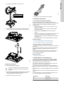 7
7
-
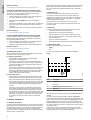 8
8
-
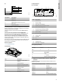 9
9
-
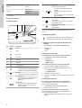 10
10
-
 11
11
-
 12
12
-
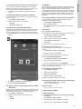 13
13
-
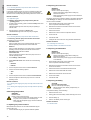 14
14
-
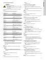 15
15
-
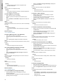 16
16
-
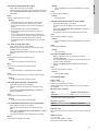 17
17
-
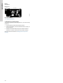 18
18
-
 19
19
-
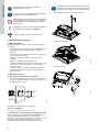 20
20
-
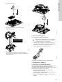 21
21
-
 22
22
-
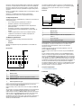 23
23
-
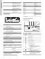 24
24
-
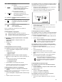 25
25
-
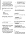 26
26
-
 27
27
-
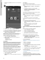 28
28
-
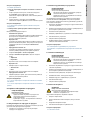 29
29
-
 30
30
-
 31
31
-
 32
32
-
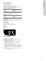 33
33
-
 34
34
-
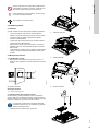 35
35
-
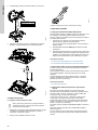 36
36
-
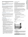 37
37
-
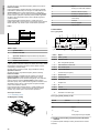 38
38
-
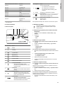 39
39
-
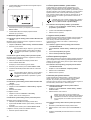 40
40
-
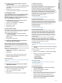 41
41
-
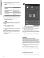 42
42
-
 43
43
-
 44
44
-
 45
45
-
 46
46
-
 47
47
-
 48
48
-
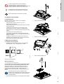 49
49
-
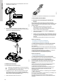 50
50
-
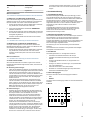 51
51
-
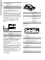 52
52
-
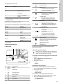 53
53
-
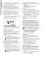 54
54
-
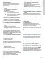 55
55
-
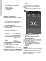 56
56
-
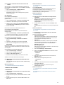 57
57
-
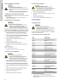 58
58
-
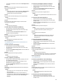 59
59
-
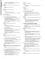 60
60
-
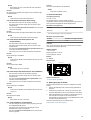 61
61
-
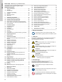 62
62
-
 63
63
-
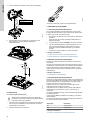 64
64
-
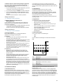 65
65
-
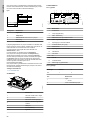 66
66
-
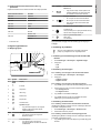 67
67
-
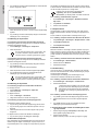 68
68
-
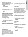 69
69
-
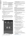 70
70
-
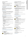 71
71
-
 72
72
-
 73
73
-
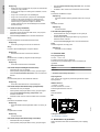 74
74
-
 75
75
-
 76
76
-
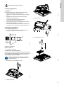 77
77
-
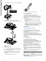 78
78
-
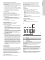 79
79
-
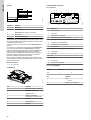 80
80
-
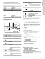 81
81
-
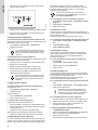 82
82
-
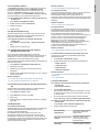 83
83
-
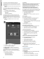 84
84
-
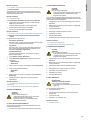 85
85
-
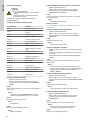 86
86
-
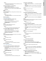 87
87
-
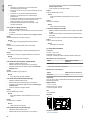 88
88
-
 89
89
-
 90
90
-
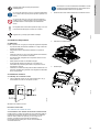 91
91
-
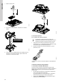 92
92
-
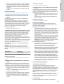 93
93
-
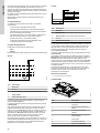 94
94
-
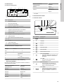 95
95
-
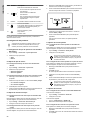 96
96
-
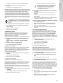 97
97
-
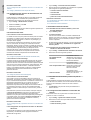 98
98
-
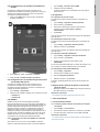 99
99
-
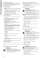 100
100
-
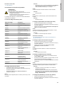 101
101
-
 102
102
-
 103
103
-
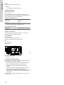 104
104
-
 105
105
-
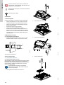 106
106
-
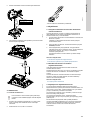 107
107
-
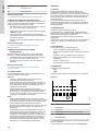 108
108
-
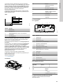 109
109
-
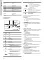 110
110
-
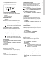 111
111
-
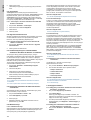 112
112
-
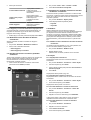 113
113
-
 114
114
-
 115
115
-
 116
116
-
 117
117
-
 118
118
-
 119
119
-
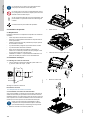 120
120
-
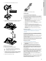 121
121
-
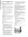 122
122
-
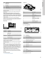 123
123
-
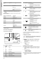 124
124
-
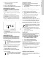 125
125
-
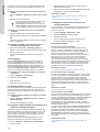 126
126
-
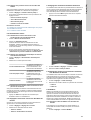 127
127
-
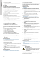 128
128
-
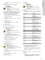 129
129
-
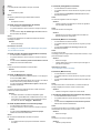 130
130
-
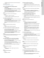 131
131
-
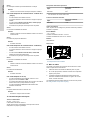 132
132
-
 133
133
-
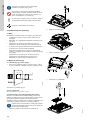 134
134
-
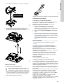 135
135
-
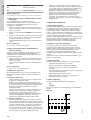 136
136
-
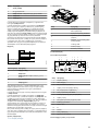 137
137
-
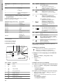 138
138
-
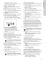 139
139
-
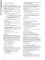 140
140
-
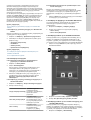 141
141
-
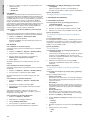 142
142
-
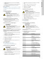 143
143
-
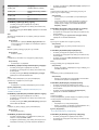 144
144
-
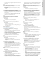 145
145
-
 146
146
-
 147
147
-
 148
148
-
 149
149
-
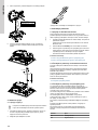 150
150
-
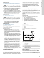 151
151
-
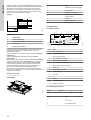 152
152
-
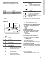 153
153
-
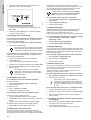 154
154
-
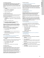 155
155
-
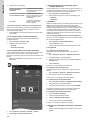 156
156
-
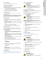 157
157
-
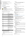 158
158
-
 159
159
-
 160
160
-
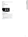 161
161
-
 162
162
-
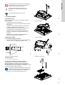 163
163
-
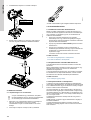 164
164
-
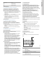 165
165
-
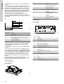 166
166
-
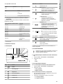 167
167
-
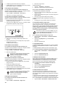 168
168
-
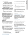 169
169
-
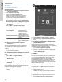 170
170
-
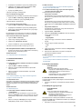 171
171
-
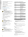 172
172
-
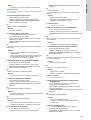 173
173
-
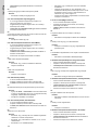 174
174
-
 175
175
-
 176
176
-
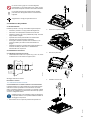 177
177
-
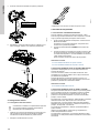 178
178
-
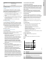 179
179
-
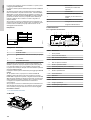 180
180
-
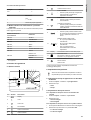 181
181
-
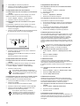 182
182
-
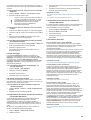 183
183
-
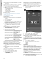 184
184
-
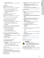 185
185
-
 186
186
-
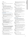 187
187
-
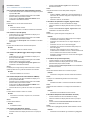 188
188
-
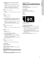 189
189
-
 190
190
-
 191
191
-
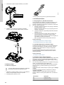 192
192
-
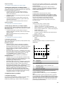 193
193
-
 194
194
-
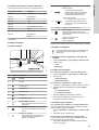 195
195
-
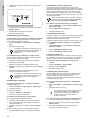 196
196
-
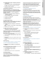 197
197
-
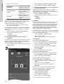 198
198
-
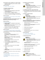 199
199
-
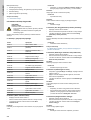 200
200
-
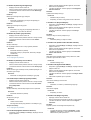 201
201
-
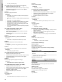 202
202
-
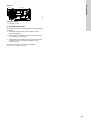 203
203
-
 204
204
-
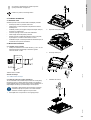 205
205
-
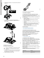 206
206
-
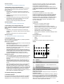 207
207
-
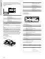 208
208
-
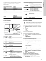 209
209
-
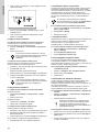 210
210
-
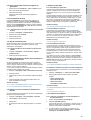 211
211
-
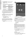 212
212
-
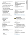 213
213
-
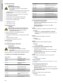 214
214
-
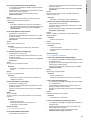 215
215
-
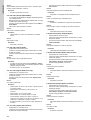 216
216
-
 217
217
-
 218
218
-
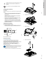 219
219
-
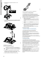 220
220
-
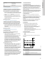 221
221
-
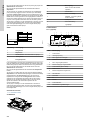 222
222
-
 223
223
-
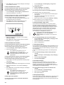 224
224
-
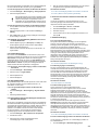 225
225
-
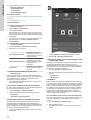 226
226
-
 227
227
-
 228
228
-
 229
229
-
 230
230
-
 231
231
-
 232
232
-
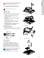 233
233
-
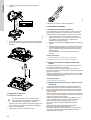 234
234
-
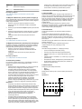 235
235
-
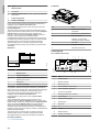 236
236
-
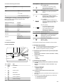 237
237
-
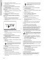 238
238
-
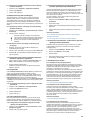 239
239
-
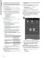 240
240
-
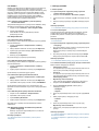 241
241
-
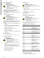 242
242
-
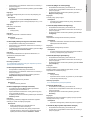 243
243
-
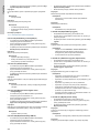 244
244
-
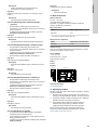 245
245
-
 246
246
-
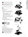 247
247
-
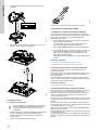 248
248
-
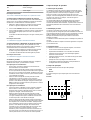 249
249
-
 250
250
-
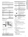 251
251
-
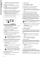 252
252
-
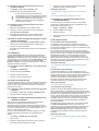 253
253
-
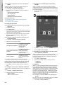 254
254
-
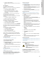 255
255
-
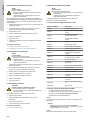 256
256
-
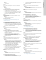 257
257
-
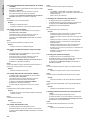 258
258
-
 259
259
-
 260
260
-
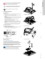 261
261
-
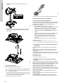 262
262
-
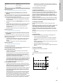 263
263
-
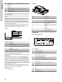 264
264
-
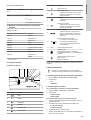 265
265
-
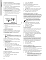 266
266
-
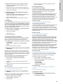 267
267
-
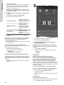 268
268
-
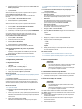 269
269
-
 270
270
-
 271
271
-
 272
272
-
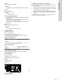 273
273
-
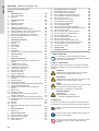 274
274
-
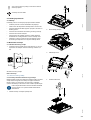 275
275
-
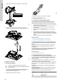 276
276
-
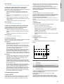 277
277
-
 278
278
-
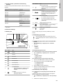 279
279
-
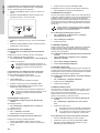 280
280
-
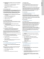 281
281
-
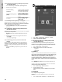 282
282
-
 283
283
-
 284
284
-
 285
285
-
 286
286
-
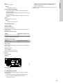 287
287
-
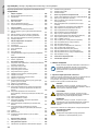 288
288
-
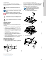 289
289
-
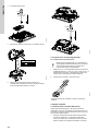 290
290
-
 291
291
-
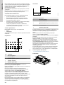 292
292
-
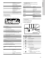 293
293
-
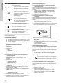 294
294
-
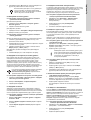 295
295
-
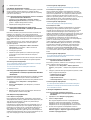 296
296
-
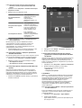 297
297
-
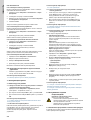 298
298
-
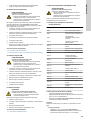 299
299
-
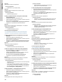 300
300
-
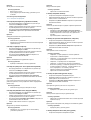 301
301
-
 302
302
-
 303
303
-
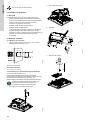 304
304
-
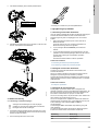 305
305
-
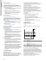 306
306
-
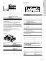 307
307
-
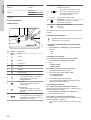 308
308
-
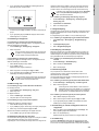 309
309
-
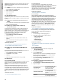 310
310
-
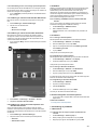 311
311
-
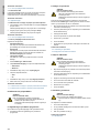 312
312
-
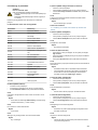 313
313
-
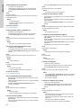 314
314
-
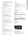 315
315
-
 316
316
-
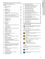 317
317
-
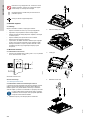 318
318
-
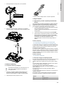 319
319
-
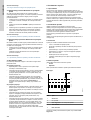 320
320
-
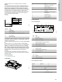 321
321
-
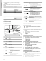 322
322
-
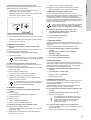 323
323
-
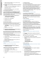 324
324
-
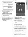 325
325
-
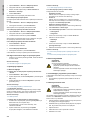 326
326
-
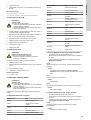 327
327
-
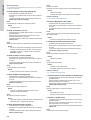 328
328
-
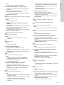 329
329
-
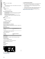 330
330
-
 331
331
-
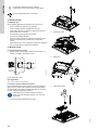 332
332
-
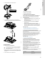 333
333
-
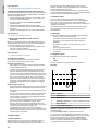 334
334
-
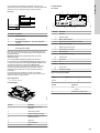 335
335
-
 336
336
-
 337
337
-
 338
338
-
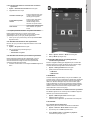 339
339
-
 340
340
-
 341
341
-
 342
342
-
 343
343
-
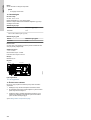 344
344
-
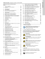 345
345
-
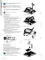 346
346
-
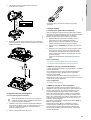 347
347
-
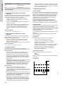 348
348
-
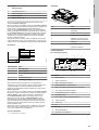 349
349
-
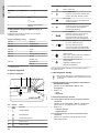 350
350
-
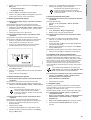 351
351
-
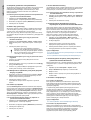 352
352
-
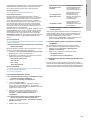 353
353
-
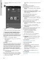 354
354
-
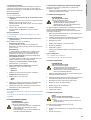 355
355
-
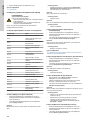 356
356
-
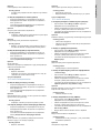 357
357
-
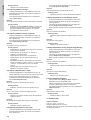 358
358
-
 359
359
-
 360
360
-
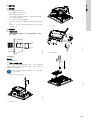 361
361
-
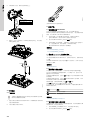 362
362
-
 363
363
-
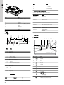 364
364
-
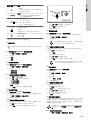 365
365
-
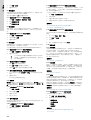 366
366
-
 367
367
-
 368
368
-
 369
369
-
 370
370
-
 371
371
-
 372
372
-
 373
373
-
 374
374
-
 375
375
-
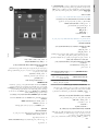 376
376
-
 377
377
-
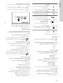 378
378
-
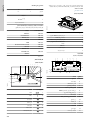 379
379
-
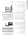 380
380
-
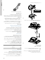 381
381
-
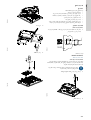 382
382
-
 383
383
-
 384
384
-
 385
385


Grundfos CU 241 Installation And Operating Instructions Manual
- Tip
- Installation And Operating Instructions Manual
Lucrări conexe
-
Grundfos APG.50.12.1 Installation And Operating Instructions Manual
-
Grundfos LCD 108 Installation And Operating Instructions Manual
-
-
-
-
-
-
-
Grundfos DME 940 Installation And Operating Instructions Manual
-
Alte documente
-
Sulzer AquaPlug - XJ/XJS Starting And Operating Instructions
-
 Reflex Refix DE 8 Manualul proprietarului
-
 Xxxlutz Regale/30-3er Assembly Instructions
-
DAB Esybox Max Instrucțiuni de utilizare
-
Vortex M 153 Operating Instructions Manual
-
Danfoss IHx Controllers - PM2+P, PTC2+P, IHPT - PN16 Instrucțiuni de utilizare
-
Osram LF1500I-G1-840-48-12 L1 User Instruction
-
-

