
GRUNDFOS INSTRUCTIONS
APG
Installation and operating instructions
www.motralec.com

Declaration of conformity
2
Declaration of conformity
GB: EC declaration of conformity
We, Grundfos, declare under our sole responsibility that the product
APG, to which this declaration relates, is in conformity with these
Council directives on the approximation of the laws of the EC member
states:
— Machinery Directive (98/37/EC).
— Low Voltage Directive (2006/95/EC).
Standards used: EN 60335-1:2002, EN 60335-2-41:2003.
— EMC Directive (89/336/EEC).
Standards used: EN 61000-6-2, EN 61000-6-3.
This EC declaration of conformity is only valid when published as part
of the Grundfos installation and operating instructions (publication
number 96434822 0912).
BG: EC декларация за съответствие
Ние, фирма Grundfos, заявяваме с пълна отговорност, че продукта
APG, за който се отнася настоящата декларация, отговаря на
следните указания на Съвета за уеднаквяване на правните
разпоредби на държавите членки на ЕС:
– Директива за машините (98/37/EC).
– Директива за нисковолтови системи (2006/95/EC).
Приложени стандарти: EN 60335-1:2002, EN 60335-2-41:2003.
– Директива за електромагнитна съвместимост (89/336/EEC).
Приложени стандарти: EN 61000-6-2, EN 61000-6-3.
Тази ЕС декларация за
съответствие е валидна само когато е
публикувана като част от инструкциите за монтаж и експлоатация
на Grundfos (номер на публикацията 96434822 0912).
DK: EF-overensstemmelseserklæring
Vi, Grundfos, erklærer under ansvar at produktet APG som denne
erklæring omhandler, er i overensstemmelse med disse af Rådets
direktiver om indbyrdes tilnærmelse til EF-medlemsstaternes
lovgivning:
— Maskindirektivet (98/37/EF).
— Lavspændingsdirektivet (2006/95/EF).
Anvendte standarder: EN 60335-1:2002, EN 60335-2-41:2003.
— EMC-direktivet (89/336/EØF).
Anvendte standarder: EN 61000-6-2, EN 61000-6-3.
Denne EF-overensstemmelseserklæring er kun gyldig når den
publiceres som en del af Grundfos-monterings- og driftsinstruktionen
(publikationsnummer 96434822 0912).
DE: EG-Konformitätserklärung
Wir, Grundfos, erklären in alleiniger Verantwortung, dass das Produkt
APG, auf das sich diese Erklärung bezieht, mit den folgenden
Richtlinien des Rates zur Angleichung der Rechtsvorschriften der
EU-Mitgliedsstaaten übereinstimmt:
— Maschinenrichtlinie (98/37/EG).
— Niederspannungsrichtlinie (2006/95/EG).
Normen, die verwendet wurden: EN 60335-1:2002,
EN 60335-2-41:2003.
— EMV-Richtlinie (89/336/EWG).
Normen, die verwendet wurden: EN 61000-6-2, EN 61000-6-3.
Diese EG-Konformitätserklärung gilt nur, wenn sie in Verbindung mit der
Grundfos Montage- und Betriebsanleitung (Veröffentlichungsnummer
96434822 0912) veröffentlicht wird.
GR: ∆ήλωση συμμόρφωσης EC
Εμείς, η Grundfos, δηλώνουμε με αποκλειστικά δική μας ευθύνη ότι τα
προϊόντα APG, στα οποία αναφέρεται η παρούσα δήλωση,
συμμορφώνονται με τις εξής Οδηγίες του Συμβουλίου περί
προσέγγισης των νομοθεσιών των κρατών μελών της ΕΕ:
— Οδηγία για μηχανήματα (98/37/EC).
— Οδηγία χαμηλής τάσης (2006/95/EC).
Πρότυπα που χρησιμοποιήθηκαν: EN 60335-1:2002,
EN 60335-2-41:2003.
— Οδηγία Ηλεκτρομαγνητικής Συμβατότητας (EMC) (89/336/EOK).
Πρότυπα που χρησιμοποιήθηκαν: EN 61000-6-2, EN 61000-6-3.
Αυτή
η δήλωση συμμόρφωσης EC ισχύει μόνον όταν συνοδεύει τις
οδηγίες εγκατάστασης και λειτουργίας της Grundfos (κωδικός εντύπου
96434822 0912).
ES: Declaración CE de conformidad
Nosotros, Grundfos, declaramos bajo nuestra propia responsabilidad
que el producto APG, al cual se refiere esta declaración, está conforme
con las Directivas del Consejo en la aproximación de las leyes de los
Estados Miembros del EM:
— Directiva de Maquinaria (98/37/CE).
— Directiva de Baja Tensión (2006/95/CE).
Normas aplicadas: EN 60335-1:2002, EN 60335-2-41:2003.
— Directiva EMC (89/336/CEE).
Normas aplicadas: EN 61000-6-2, EN 61000-6-3.
Esta declaración CE de conformidad sólo es válida cuando se publique
como parte de las instrucciones de instalación y funcionamiento de
Grundfos (número de publicación 96434822 0912).
FR : Déclaration de conformité CE
Nous, Grundfos, déclarons sous notre seule responsabilité, que
le produit APG, auquel se réfère cette déclaration, est conforme aux
Directives du Conseil concernant le rapprochement des législations
des Etats membres CE relatives aux normes énoncées ci-dessous:
— Directive Machines (98/37/CE).
— Directive Basse Tension (2006/95/CE).
Normes utilisées: EN 60335-1:2002, EN 60335-2-41:2003.
— Directive Compatibilité Electromagnétique CEM (89/336/CEE).
Normes utilisées: EN 61000-6-2, EN 61000-6-3.
Cette déclaration de conformité CE est uniquement valide lors de sa
publication dans la notice d'installation et de fonctionnement Grundfos
(numéro de publication 96434822 0912).
HR: EZ izjava o usklađenosti
Mi, Grundfos, izjavljujemo pod vlastitom odgovornošću da je proizvod
APG, na koji se ova izjava odnosi, u skladu s direktivama ovog Vijeća
o usklađivanju zakona država članica EU:
— Direktiva za strojeve (98/37/EZ).
— Direktiva za niski napon (2006/95/EZ).
Korištene norme: EN 60335-1:2002, EN 60335-2-41:2003.
— Direktiva za elektromagnetsku kompatibilnost (89/336/EEC).
Korištene norme: EN 61000-6-2, EN 61000-6-3.
Ova EZ izjava o suklađnosti važeća je jedino kada je izdana kao dio
Grundfos montažnih i pogonskih uputa (broj izdanja 96434822 0912).
IT: Dichiarazione di conformità CE
Grundfos dichiara sotto la sua esclusiva responsabilità che il prodotto
APG, al quale si riferisce questa dichiarazione, è conforme alle
seguenti direttive del Consiglio riguardanti il riavvicinamento delle
legislazioni degli Stati membri CE:
— Direttiva Macchine (98/37/CE).
— Direttiva Bassa Tensione (2006/95/CE).
Norme applicate: EN 60335-1:2002, EN 60335-2-41:2003.
— Direttiva EMC (89/336/CEE).
Norme applicate: EN 61000-6-2, EN 61000-6-3.
Questa dichiarazione di conformità CE è valida solo quando pubblicata
come parte delle istruzioni di installazione e funzionamento Grundfos
(pubblicazione numero 96434822 0912).
HU: EK megfelelőségi nyilatkozat
Mi, a Grundfos, egyedüli felelősséggel kijelentjük, hogy a APG termék,
amelyre jelen nyilatkozik vonatkozik, megfelel az Európai Unió
tagállamainak jogi irányelveit összehangoló tanács alábbi előírásainak:
— Gépek (98/37/EK).
— Kisfeszültségű Direktíva (2006/95/EK).
Alkalmazott szabványok: EN 60335-1:2002,
EN 60335-2-41:2003.
— EMC Direktíva (89/336/EEC).
Alkalmazott szabványok: EN 61000-6-2, EN 61000-6-3.
Ez az EK megfelelőségi nyilatkozat kizárólag akkor érvényes, ha
Grundfos telepítési és üzemeltetési utasítás (kiadvány szám 96434822
0912) részeként kerül kiadásra.
www.motralec.com

Declaration of conformity
3
NL: EC overeenkomstigheidsverklaring
Wij, Grundfos, verklaren geheel onder eigen verantwoordelijkheid dat
het product APG waarop deze verklaring betrekking heeft, in
overeenstemming is met de Richtlijnen van de Raad in zake de
onderlinge aanpassing van de wetgeving van de EG lidstaten
betreffende:
— Machine Richtlijn (98/37/EC).
— Laagspannings Richtlijn (2006/95/EC).
Gebruikte normen: EN 60335-1:2002, EN 60335-2-41:2003.
— EMC Richtlijn (89/336/EEC).
Gebruikte normen: EN 61000-6-2, EN 61000-6-3.
Deze EC overeenkomstigheidsverklaring is alleen geldig wanneer deze
gepubliceerd is als onderdeel van de Grundfos installatie- en
bedieningsinstructies (publicatienummer 96434822 0912).
PT: Declaração de conformidade CE
A Grundfos declara sob sua única responsabilidade que o produto
APG, ao qual diz respeito esta declaração, está em conformidade com
as seguintes Directivas do Conselho sobre a aproximação das
legislações dos Estados Membros da CE:
— Directiva Máquinas (98/37/CE).
— Directiva Baixa Tensão (2006/95/CE).
Normas utilizadas: EN 60335-1:2002, EN 60335-2-41:2003.
— Directiva EMC (compatibilidade electromagnética) (89/336/CEE).
Normas utilizadas: EN 61000-6-2, EN 61000-6-3.
Esta declaração de conformidade CE é apenas válida quando
publicada como parte das instruções de instalação e funcionamento
Grundfos (número de publicação 96434822 0912).
RU: Декларация о соответствии ЕС
Мы, компания Grundfos, со всей ответственностью заявляем,
что изделия APG, к которым относится настоящая декларация,
соответствуют следующим Директивам Совета Евросоюза об
унификации законодательных предписаний стран-членов ЕС:
— Механические устройства (98/37/ЕС).
— Низковольтное оборудование (2006/95/EC).
Применявшиеся стандарты: EN 60335-1:2002,
EN 60335-2-41:2003.
— Электромагнитная совместимость (89/336/ЕЭС).
Применявшиеся стандарты: EN 61000-6-2, EN 61000-6-3.
Данная декларация о соответствии ЕС имеет силу только в случае
публикации в составе
инструкции по монтажу и эксплуатации на
продукцию производства компании Grundfos (номер публикации
96434822 0912).
RO: Declaraţie de conformitate CE
Noi, Grundfos, declarăm pe propria răspundere că produsele APG,
la care se referă această declaraţie, sunt în conformitate cu aceste
Directive de Consiliu asupra armonizării legilor Statelor Membre CE:
— Directiva Utilaje (98/37/CE).
— Directiva Tensiune Joasă (2006/95/CE).
Standarde utilizate: EN 60335-1:2002, EN 60335-2-41:2003.
— Directiva EMC (89/336/CEE).
Standarde utilizate: EN 61000-6-2, EN 61000-6-3.
Această declarație de conformitate CE este valabilă numai când este
publicată ca parte a instrucțiunilor Grundfos de instalare și funcționare
(număr publicație 96434822 0912).
RS: EC deklaracija o usaglašenosti
Mi, Grundfos, izjavljujemo pod vlastitom odgovornošću da je proizvod
APG, na koji se ova izjava odnosi, u skladu sa direktivama Saveta
za usklađivanje zakona država članica EU:
— Direktiva za mašine (98/37/EC).
— Direktiva niskog napona (2006/95/EC).
Korišćeni standardi: EN 60335-1:2002, EN 60335-2-41:2003.
— EMC direktiva (89/336/EEC).
Korišćeni standardi: EN 61000-6-2, EN 61000-6-3.
Ova EC deklaracija o usaglašenosti važeća je jedino kada je izdata kao
deo Grundfos uputstava za instalaciju i rad (broj izdanja 96434822
0912).
FI: EY-vaatimustenmukaisuusvakuutus
Me, Grundfos, vakuutamme omalla vastuullamme, että tuote APG,
jota tämä vakuutus koskee, on EY:n jäsenvaltioiden lainsäädännön
yhdenmukaistamiseen tähtäävien Euroopan neuvoston direktiivien
vaatimusten mukainen seuraavasti:
— Konedirektiivi (98/37/EY).
— Pienjännitedirektiivi (2006/95/EY).
Sovellettavat standardit: EN 60335-1:2002, EN 60335-2-41:2003.
— EMC-direktiivi (89/336/ETY).
Sovellettavat standardit: EN 61000-6-2, EN 61000-6-3.
Tämä EY-vaatimustenmukaisuusvakuutus on voimassa vain, kun se
julkaistaan osana Grundfosin asennus- ja käyttöohjeita (julkaisun
numero 96434822 0912).
SE: EG-försäkran om överensstämmelse
Vi, Grundfos, försäkrar under ansvar att produkten APG, som omfattas
av denna försäkran, är i överensstämmelse med rådets direktiv om
inbördes närmande till EU-medlemsstaternas lagstiftning, avseende:
— Maskindirektivet (98/37/EG).
— Lågspänningsdirektivet (2006/95/EG).
Tillämpade standarder: EN 60335-1:2002, EN 60335-2-41:2003.
— EMC-direktivet (89/336/EEG).
Tillämpade standarder: EN 61000-6-2, EN 61000-6-3.
Denna EG-försäkran om överensstämmelse är endast giltig när den
publiceras som en del av Grundfos monterings- och driftsinstruktion
(publikation nummer 96434822 0912).
CN: EC 产品合格声明书
我们格兰富在我们的全权责任下声明,产品 APG,即该合格证所指之产
品,符合欧共体使其成员国法律趋于一致的以下欧共理事会指令:
– 机械设备指令 (98/37/EC)
– 低电压指令 (2006/95/EC)。
所用标准 : EN 60335-1:2002, EN 60335-2-41:2003。
– 电磁兼容性指令 (89/336/EEC)。
所用标准 : EN 61000-6-2, EN 61000-6-3。
本 EC 合格性声明仅在作为格兰富安装与操作指导手册 (出版号
96434822 0912)的一部分时有效。
Bjerringbro, 15th August 2012
Jan Strandgaard
Technical Director
Grundfos Holding A/S
Poul Due Jensens Vej 7
8850 Bjerringbro, Denmark
Person authorised to compile technical file and
empowered to sign the EC declaration of conformity.
www.motralec.com

Declaration of conformity
4
Декларация о соответствии на территории РФ
Насосы серии APG сертифицированы на соответствие
требованиям Технического регламента о безопасности машин и
оборудования (Постановление правительства РФ от 15.09.2009
№753).
Сертификат соответствия:
№ C-DK.АИ30.B.02496, срок действия до 22.12.2016г.
Истра, 1 августа 2012 г.
Касаткина В. В.
Руководитель отдела качества,
экологии и охраны труда
ООО Грундфос Истра, Россия
143581, Московская область,
Истринский район,
дер. Лешково, д.188
www.motralec.com

English (GB)
5
English (GB) Installation and operating instructions
Original installation and operating instructions.
CONTENTS
Page
1. Symbols used in this document
2. General description
2.1 Applications
Grundfos APG pumps are designed for pumping:
• wastewater
• sludge-containing water
• groundwater
• sewage from restaurants, hotels, camping sites,
etc.
The compact design makes the pumps suitable for
both temporary and permanent installation.
Furthermore, the pumps are suitable for free-
standing installation as well as installation on an
auto-coupling system.
The APG pumps are equipped with a cutter system
which cuts all destructible solids into small pieces so
that they can be led away through pipes of a
relatively small diameter.
2.1.1 Potentially explosive environments
Use the explosion-proof APG pump versions for
applications involving a risk of explosion.
2.2 Operating conditions
2.2.1 pH-value
APG pumps in permanent installations can cope with
pH-values ranging from 4 to 10.
2.2.2 Liquid temperature
Liquid temperature: 0 °C to +40 °C.
For short periods up to +60 °C.
2.2.3 Density of pumped liquid
Maximum density of pumped liquid: 1100 kg/m
3
.
2.2.4 Installation depth
Maximum 10 metres below liquid level.
1. Symbols used in this document
5
2. General description
5
2.1 Applications
5
2.2 Operating conditions
5
2.3 Sound pressure level
6
3. Safety
6
4. Transportation and storage
6
5. Installation
6
5.1 Installation on auto-coupling
6
5.2 Free-standing installation
6
5.3 Pumps with control box
7
5.4 Separate level controllers
7
6. Electrical connection
7
6.1 Motor protection
7
7. Start-up
9
7.1 Direction of rotation
9
8. Maintenance and service
10
8.1 Replacement of cutter head
10
8.2 Service kits
11
8.3 Oil
11
8.4 Contaminated pumps
11
9. Fault finding
12
10. Disposal
12
Warning
Prior to installation, read these
installation and operating instructions.
Installation and operation must comply
with local regulations and accepted
codes of good practice.
Warning
If these safety instructions are not
observed, it may result in personal
injury.
Warning
If these instructions are not observed,
it may lead to electric shock with
consequent risk of serious personal
injury or death.
Warning
These instructions must be observed
for explosion-proof pumps. It is
advisable also to follow these
instructions for standard pumps.
Caution
If these safety instructions are not
observed, it may result in malfunction
or damage to the equipment.
Note
Notes or instructions that make the job
easier and ensure safe operation.
Note
If you order an explosion-proof pump,
you will receive a pump not labelled
Grundfos.
We must emphasize that we comply
with all obligations with respect to
warranty and service of pumps sold by
Grundfos as APG pumps.
Note
The explosion classification of the
pumps is EEx de IIB T4. However, the
pumps must in each individual case be
approved for use at the desired
installation site by the local authorities.
www.motralec.com

English (GB)
6
2.2.5 Level of pumped liquid
The lowest stop level must always be above the top
of the pump housing.
2.2.6 Operation
Maximum 20 starts per hour.
2.3 Sound pressure level
The sound pressure level of the pump is lower than
the limiting values stated in the EC Council Directive
98/37/EEC relating to machinery.
3. Safety
4. Transportation and storage
The pump may be transported and stored in a
vertical or horizontal position. Make sure that it
cannot roll or fall over.
Always lift the pump by its carrying handle, never by
the motor cable or the hose/pipe.
For long periods of storage, the pump must be
protected against moisture and heat.
After a long period of storage, the pump should be
inspected before it is put into operation. Make sure
that the impeller can rotate freely. Pay special
attention to the shaft seals and the cable entry.
5. Installation
The extra nameplate supplied with the pump should
be fixed at the installation site.
Prior to installation, check the oil level in the oil
chamber. See section 8. Maintenance and service.
5.1 Installation on auto-coupling
See figures 1 and 2, pages 155 and 156, for pumps
up to and including 3.3 kW and fig. 4, page 158, for
pumps from 4.8 kW up to and including 9.2 kW.
Pumps for permanent installation can be installed on
a stationary auto-coupling and operated completely
or partially submerged in the pumped liquid.
1. Drill mounting holes for the guide rail bracket on
the inside of the pit, and fasten the guide rail
bracket provisionally with two screws.
2. Place the auto-coupling base unit on the bottom
of the pit. Use a plumb line to establish the
correct position. Fasten the auto-coupling base
unit with heavy-duty expansion bolts. If the
bottom of the pit is uneven, the auto-coupling
base unit must be supported so that it is level
when fastened.
3. Assemble the discharge line in accordance with
the generally accepted procedures and without
exposing the line to distortion or tension.
4. Insert the guide rails in the rings of the auto-
coupling base unit, and adjust the length of the
rails accurately to the guide rail bracket.
5. Unscrew the provisionally fastened guide rail
bracket, fit it on top of the guide rails, and finally
fasten it firmly to the pit wall.
6. Clean out debris from the pit before lowering the
pump into the pit.
7. Fit the auto-coupling half on the discharge port of
the pump. Then slide the guide bar of this
coupling half between the guide rails, and lower
the pump into the pit by means of a chain. When
the pump reaches the auto-coupling base unit,
the pump will automatically connect tightly.
8. Hang the end of the chain on a suitable hook at
the top of the pit.
9. Adjust the length of the motor cable by coiling it
up on a relief fitting so the cable is not damaged
during operation. Fasten the relief fitting to a
suitable bracket at the top of the pit. Make sure
that the cables are not sharply bent or pinched.
5.2 Free-standing installation
See figures 3 and 5, pages 157 and 158.
The APG.50.11.3 and APG.50.12.1 pumps have
pump housing and base stand cast in one piece for
free-standing installation.
The larger APG pumps should be provided with a
separate base stand.
For free-standing installation of the pumps, fit a 90 °
elbow on the discharge port. The pump can be
installed with a hose or rigid pipe and valves.
In order to facilitate service of the pump, fit a flexible
union or coupling to the discharge line for easy
separation.
If a hose is used, make sure that the hose does not
buckle, and that the inside diameter of the hose
matches that of the discharge port.
If a rigid pipe is used, the union or coupling, non-
return valve and isolating valve should be fitted in
the sequence mentioned, as seen from the pump
side.
Lower the pump into the liquid.
If the pump is installed in muddy conditions or on
uneven ground, we recommend placing the pump on
bricks.
Note
The pumps are designed for
intermittent operation only.
Warning
Pump installation in wells must be
carried out by specially trained
persons.
Caution
The guide rails must not have any axial
play as this would cause noise during
pump operation.
Caution
The end of the cable must not be
submerged, as water may penetrate
through the cable into the motor.
www.motralec.com

English (GB)
7
5.3 Pumps with control box
Pumps with a control box may be supplied with a
level switch with cable. The level switch cable should
be fastened in the retainer on the pump handle.
The level difference between start and stop may be
adjusted by adjusting the free length of cable
between the level switch and the retainer.
Large difference in level: long cable. Small difference
in level: short cable.
5.4 Separate level controllers
Three-phase APG pumps without control box or level
switch can be supplied with a separate level
controller with level switches: type LC for one-pump
installations and type LCD for two-pump
installations.
The LC controller is fitted with two or three level
switches. The third level switch, which is optional, is
for high-level alarm.
The LCD controller is fitted with three or four level
switches: one for common stop and two for start of
pumps. The fourth level switch, which is optional, is
for high-level alarm.
When installing the level switches, the following
points should be observed:
• To prevent air intake and vibrations, install the
stop level switch in such a way that the pump is
stopped before the liquid level falls to below the
top of the pump housing.
• Install the start level switch in such a way that the
pump is started at the required level. However,
the pump must always be started before the
liquid level reaches the bottom inlet pipe in the
pit.
• If installed, the high-level alarm switch should
always be placed about 10 cm above the start
level switch. However, alarm must always be
given before the liquid level reaches the pit inlet
pipe.
6. Electrical connection
The electrical connection of the pump should be
carried out in accordance with local regulations.
The operating voltage and frequency are stated on
the nameplate. Voltage tolerance: ± 10 % of the
voltage stated on the nameplate. Make sure that the
motor is suitable for the power supply available at
the installation site.
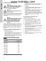
6.1 Motor protection
All pumps are supplied with 10 metres of cable and a
free cable end.
All single-phase pumps supplied without control box
must be connected to a separate control box with
motor starter and run capacitor. Furthermore, the
pumps must be connected to a starting capacitor.
For capacitor sizes, see the table below.
60 Hz
APG.50.12.1 has a thermal switch built into the motor
windings. The thermal switch cuts out the motor in
case of overtemperature and cuts it in again
automatically after cooling.
All 3-phase pumps supplied without control box must
be connected to a separate motor starter.
APG pumps of 4.8 kW and up are prepared for star-
delta starting, i.e. both ends of the motor windings
are accessible through the motor cable. See fig. 1.
• T1 and T3 are connected to the standard set of
temperature sensors.
• T1 and T2 are connected to the extra set of
temperature sensors in explosion-proof pumps.
• S1 and S2 are connected to a moisture sensor in
the oil chamber.
Note
To ensure correct operation of the
pump, make sure to adjust and fit the
level sensor correctly. Carry out a test
run of the pump after each adjustment
of the level sensor.
Pump type
Starting
capacitor
Run
capacitor
[μF] [V] [μF] [V]
APG.50.12.1 50 1 x 230 25 1 x 450
APG.50.18.1 80 1 x 230 40 1 x 450
APG.50.30.1 150 1 x 230 60 1 x 450
APG.50.33.1 150 1 x 230 60 1 x 450
www.motralec.com

English (GB)
8
6.1.1 Temperature sensors (in stator windings)
All pumps have integrated temperature sensors in
the stator windings. Via the safety circuit, the
temperature sensors will cut out the motor in case of
overtemperature, approx. 140 °C. The maximum
operating current of the temperature sensors is 0.5 A
at 500 VAC and cos φ 0.6.
Non-explosion-proof pumps only have one set of
temperature sensors.
Explosion-proof pumps have two sets of temperature
sensors. The extra set of sensors will open at a
temperature that is approx. 10 °C higher than the
opening temperature of standard sensors. The extra
set of sensors provides additional protection against
overtemperature in potentially explosive
environments.
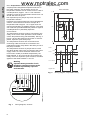
The temperature sensors must be connected to the
safety circuit of the motor-protective circuit breaker
via the temperature relay (No 98123042). See fig. 2.
Figure 1 shows the electrical connection of a three-
phase, explosion-proof APG pump.
The temperature sensors are connected to the
monitoring cable and must be connected to the
separate thermistor relay fitted in the safety circuit of
the pump controller.
The temperature sensors of pumps above 1.6 kW
and three-phase motors are connected to the power
supply cable. To ensure automatic restart of the
motor when cooled (to ambient temperature), the
leads marked T1 and T3 must be connected to the
safety circuit. For explosion-proof versions, the same
applies to the leads marked T1 and T2.
Fig. 1 Wiring diagram, sensors
Temperature relay
Fig. 2 Wiring diagram, temperature relay
Warning
Separate motor-protective circuit
breakers/control boxes must not be
installed in potentially explosive
environments.
TM05 2157 4511
+10°C 140°C
U1PE
U
2
V1 V2 W1 W2 T1 T2 T3 S1 S2
TM05 3448 1312
.ȍ
.ȍ
A1/A2
T1/T2
13-14, 21-22
Tripped LED
EMT6-DB AUTO
L +
N
U
S
A1
21 13
A2
T1
T2/T3
22
14
PTC
Power
Tripped
www.motralec.com

English (GB)
9
6.1.2 Moisture sensor
Applies only to APG.50.48, APG.50.65 and
APG.50.92.
Pumps with moisture sensor have a sensor in the oil
chamber between the motor and the pump housing.
Through the separate level relay (No 98123045), the
moisture sensor transmits a signal to the safety
circuit to trip the motor in case of ingress of moisture/
water into the pump. See fig. 3.
Fig. 3 Wiring, moisture relay
7. Start-up
Proceed as follows:
1. Check the oil level in the oil chamber.
2. Remove the fuses, and check whether the
impeller can rotate freely.
3. Check whether the monitoring units, if used, are
operating satisfactorily.
4. Check whether the system has been filled with
liquid and vented.
5. Make sure that the pump is submerged in the
liquid.
6. Open the isolating valves, if fitted.
7. Check the setting of the level switches.
8. Start the pump.
7.1 Direction of rotation
All single-phase pumps are factory-set to the correct
direction of rotation.
Before starting up three-phase pumps, check the
direction of rotation. The direction of rotation should
be clockwise when viewed from above. When
starting up, the pump will jerk in the opposite
direction of the direction of rotation. If the direction of
rotation is wrong, interchange two of the three
phases of the power supply.
Checking the direction of rotation
The direction of rotation should be checked every
time the pump is connected to a new installation.
Check the direction of rotation as follows:
1. Start the pump, and check the quantity of water
or the discharge pressure.
2. Stop the pump, and interchange two of the three
phases to the motor.
3. Start the pump, and check the quantity of water
or the discharge pressure.
4. Stop the pump.
5. Compare the results from points 1 and 3. The
phase connection which gives the larger quantity
of water or the higher pressure gives the correct
direction of rotation.
TM05 2304 4811
R
U
1
2
3
4
A1 15
18 16
B3B1 B2
A2
B2
B1
B3
15
16
18
A1
A2
Note
The pump may be started for a very
short period without being submerged
in order to check the direction of
rotation.
www.motralec.com

English (GB)
10
8. Maintenance and service
Before carrying out maintenance and service, make
sure that the pump has been thoroughly flushed with
clean water. Rinse the pump parts in water after
dismantling.
Normally operating pumps should be inspected at
least once a year. If the pumped liquid is very muddy
or sandy, inspect the pump at shorter intervals.
When the pump is new or after replacement of the
shaft seals, check the oil level after one week of
operation.
For long and trouble-free operation of the pump the
following points should be checked regularly:
• Power consumption
• Oil level and oil condition
If the oil contains water, it becomes greyish white
like milk. Water in the oil may be due to a
defective shaft seal. The oil should be replaced
after 3000 hours of operation. Use Shell Ondina
934 oil or a similar type of oil.
• Cable entry
Make sure that the cable entry is watertight and
that the cables are not bent sharply and/or
pinched.
• Pump parts
Check the impeller, pump housing, neck ring, etc.
for possible wear. Replace defective parts.
• Ball bearings
Check the shaft for noisy or heavy operation (turn
the shaft by hand). Replace defective ball
bearings. A general overhaul of the pump is
usually required in case of defective ball bearings
or poor motor function. This work must be carried
out by the manufacturer or a competent
workshop.
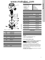
8.1 Replacement of cutter head
Remove the cutter head.
Fit the new cutter head as follows:
1. Knock guide pin (560) into cutter head (23).
2. Fit the cutter head with guide pin on impeller
(230). Fit and tighten screw (900.01).
3. Fit threaded pins (904) in suction cover (162).
4. Fit O-ring (412.01) in the suction cover, and
grease the cover.
5. Knock the suction cover into pump housing (101)
until the suction cover bears against the impeller.
Check through the inlet port.
6. Tighten all threaded pins (904) until they easily
touch pump housing (101).
7. Give all threaded pins a quarter of a turn.
8. Fasten the suction cover by means of screws
(914.01).
9. Fit cutting ring (50) to the suction cover. Fit and
tighten screws (900.02).
Warning
Before starting work on the product,
switch off the power supply. Make sure
that the power supply cannot be
accidentally switched on.
Warning
Make sure that all rotating parts have
stopped moving.
Warning
When unscrewing the inspection screw
of the oil chamber, please note that
pressure may have built up in the
chamber. Do not remove the screw
until the pressure has been fully
relieved.
Note
Used oil must be disposed of in
accordance with local regulations.
Pump type
Quantity of oil in
oil chamber [l]
APG.50.11 0.70
APG.50.12 0.70
APG.50.18 1.00
APG.50.19 1.00
APG.50.29 1.00
APG.50.30 1.00
APG.50.33 1.00
APG.50.48 1.90
APG.50.65 1.90
APG.50.92 1.90
www.motralec.com

English (GB)
11
Fig. 4 Exploded view
8.2 Service kits
8.3 Oil
1 litre of oil, type Shell Ondina 934.
Product number: 96003313.
8.4 Contaminated pumps
If Grundfos is requested to service the pump,
Grundfos must be contacted with details about the
pumped liquid, etc. before the pump is returned for
service. Otherwise Grundfos can refuse to accept
the pump for service.
Possible costs of returning the pump to the customer
are paid by the customer.
TM01 7812 4899
Pos. Component
23 Cutter head
50 Cutting ring
101 Pump housing
162 Suction cover
230 Impeller
560 Guide pin
412.01 O-ring
900.01 Screw
900.02 Screw
904 Threaded pin
914.01 Screw
The service kit for APG
pumps up to and
including 3.7 kW
includes:
1 shaft seal kit
1 O-ring kit
1 cable entry kit.
The service kit for APG
pumps of 4.8 kW and up
includes:
1 cutter kit
1 O-ring kit
1 shaft seal kit
1 cable entry kit.
50 Hz pumps
APG.50.09, 11 and 12 96003308
APG.50.09.3Ex and 11.1Ex 96003300
APG.50.17, 18 and 19 96003309
APG.50.19.3Ex 96003310
APG.50.31 96003311
APG.50.31.3Ex 96003310
APG.50.48.3(Ex) 96843315
APG.50.65.3(Ex) 96843315
APG.50.92.3(Ex) 96843315
APG.50.48.3(Ex) with
moisture sensor
96843315
APG.50.65.3(Ex) with
moisture sensor
96843315
APG.50.92.3(Ex) with
moisture sensor
96843315
60 Hz pumps
APG.50.11 and 12 96003308
APG.50.18 and 19 96003309
APG.50.29, 30 and 33 96003311
Caution
If used for a liquid which is injurious to
health or toxic, the pump will be
classified as contaminated.
www.motralec.com

English (GB)
12
9. Fault finding
10. Disposal
This product or parts of it must be disposed of in an
environmentally sound way:
1. Use the public or private waste collection service.
2. If this is not possible, contact the nearest
Grundfos company or service workshop.
Subject to alterations.
Warning
Before starting fault finding, switch off the power supply, and make sure that all rotating
parts have stopped moving. Make sure that the power supply cannot be accidentally
switched on.
Fault Cause Remedy
1. Motor does not start. Fuses
blow, or motor starter trips
immediately.
Caution: Do not start again!
a) Supply failure; short-circuit;
earth-leakage fault in cable or
motor winding.
Have the cable and motor checked
and repaired by a qualified
electrician.
b) Fuses blow as they are not
the right type.
Install fuses of the correct type.
c) Impeller blocked by impurities. Clean the impeller.
d) Level switch out of adjustment
or defective.
Check the level switch.
2. Pump operates, but motor
starter trips after a short while.
a) Low setting of thermal relay in
motor starter.
Set the relay in accordance with
the specifications on the
nameplate.
b) Increased current
consumption due to large
voltage drop.
Measure the voltage between
motor phases. Tolerance: ± 10 %.
c) Impeller blocked by impurities.
Increased current
consumption in all three
phases.
Clean the impeller.
3. Pump operates at below-
standard performance and
power consumption.
a) Impeller blocked by impurities. Clean the impeller.
Check the direction of rotation,
and, if necessary, interchange two
phases. See section 7.1 Direction
of rotation.
b) Wrong direction of rotation.
4. Pump operates, but supplies
no liquid.
a) Discharge valve closed or
blocked.
Check the discharge valve, and
open and/or clean, if necessary.
b) Non-return valve blocked. Clean the non-return valve.
Vent the pump.c) Air in pump.
www.motralec.com

Appendix
13
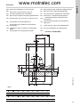
Appendix 1
Fig. 1
GB: One-pump installation on auto coupling HU: Egy szivattyú beép. automata csőkapcsolóval
BG:
Една помпа с автоматичен куплунг
NL: Eén pomp met voetbochtsnelkoppeling
DK: 1-pumpe-installation på autokobling PT: Uma bomba com acoplamento automático
DE: Ein-Pumpen-Anlage mit Kupplungsfußkrümmer RU:
Oдин насоc c автоматической муфтой
GR Εγκατάσταση μιάς αντλίας με αυτόματη ζεύξη RO:
1. Instalarea pompei pe dispozitivul de
autocuplare
ES Una bomba con autoacoplamiento RS:
Ugradnja jedne pumpe sa automatskom
spojnicom
FR:
Une pompe avec système d’accouplement
automatique
FI: Yhden pumpun asennus jalustaliittimellä
HR:
Instalacija s jednom crpkom na automatskoj
spojki
SE: En pump installerad med kopplingsfot
IT: Una pompa con accoppiamento rapido CN:
一台泵安装于自动耦合装置上
TM05 1635 3311
•
•
•
•
•
•
•
•
•
•
•
•
•
•
•
•
•
••
•
•
•
•
•
•
•
•
•
•
•
•
•
•
•
•
•
•
•
•
•
•
•
•
•
•
•
•
•
•
•
•
•
•
•
•
•
•
•
•
•
•
•
•
•
•
•
•
•
•
•
•
•
•
•
•
•
•
•
•
•
•
•
•
•
•
•
•
•
•
•
•
•
•
•
•
•
V
U
F
A
G
K
N
L
O
J
C
T
E
S
A4BC D E F G I J
∅600 ∅600 407 300 45 45 65 115 143
K L M N O P R T U V
150 400 200 300 700 500 - 1/2" 160 295
www.motralec.com

Appendix
14
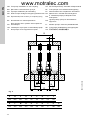
Fig. 2
GB: Two-pump installation on auto coupling HU: Két szivattyús beép. automata csőkapcsolóval
BG: Две помпи с автоматичен куплунг NL: Tvee pompen met voetbochtsnelkoppeling
DK: 2-pumpe-installation på autokobling PT: Duas bombas com acoplamento automático
DE: Zwei-Pumpen-Anlage mit Kupplungsfußkrümmer RU: Два насоса с автоматической муфтой
GR Εγκατάσταση δύο αντλιών με αυτόματη ζεύξη RO:
2. Instalarea pompei pe dispozitivul de
autocuplare
ES Dos bombas con autoacoplamiento RS:
Ugradnja dveju pumpi sa automatskom
spojnicom
FR:
Deux pompes avec système d’accouplement
automatique
FI: Kahden pumpun asennus jalustaliittimellä
HR: Instalacija s dvije crpke na automatskoj spojki SE: Två pumpar installerade med kopplingsfot
IT: Due pompe con accoppiamento rapido CN:
两台泵安装于自动耦合装置上
TM01 2607 2098
‹
‹
‹
‹
‹
‹
‹
‹
‹
‹
‹
‹
‹
‹
‹
‹
‹
‹
‹
‹
‹
‹
‹
‹
‹
B
D
I
MM
P R P
A B C D E F G I J
455 600 407 135 45 45 65 115 143
K L M N O P R T U V
150 400 200 300 700 335 330 ½” 160 295
www.motralec.com

Appendix
15
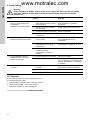
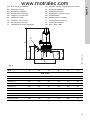
Fig. 3
GB: Free-standing Installation HU: Telepítési méretek hozdozható kivitel esetén
BG: Свободен монтаж NL: Vrijstaande opstelling
DK: Fritstående installation PT: Instalação autónoma
DE: Freistehende Aufstellung RU: Свободная установка насоса
GR Ανεξάρτητη εγκατάσταση RO: Instalare liberă
ES Instalación portátil RS: Slobodnostojeća ugradnja
FR: Installation fixe sur socle FI: Vapaasti seisova asennus
HR: Samostojeća instalacija SE: Fristående installation
IT: Installazione su piede d’appoggio CN:
独立 (潜水)安装
TM01 2603 3311
B
D
C
E
A
S
APG A B C D E S
APG, 50 Hz
APG.50.09.3 497 304 130 90 207 R 2
APG.50.09.3Ex 497 304 130 90 207 R 2
APG.50.11.1 497 304 130 90 207 R 2
APG.50.11.1Ex 497 304 130 90 207 R 2
APG.50.17.3 618 405 191 150 265 R 2
APG.50.18.1 618 405 191 150 265 R 2
APG.50.19.3 618 405 191 150 265 R 2
APG.50.19.3Ex 618 405 191 150 265 R 2
APG.50.31.3 655 408 191 150 265 R 2
APG.50.31.3Ex 655 408 191 150 265 R 2
www.motralec.com

Appendix
16
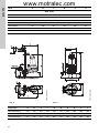
Fig. 4 Fig. 5
APG A B C D E S
APG, 60 Hz
APG.50.11.3 450 304 133 90 207 R 2
APG.50.12.1 450 304 133 90 207 R 2
APG.50.18.1 620 408 191 150 265 R 2
APG.50.19.3 620 408 191 150 265 R 2
APG.50.29.3 751 408 191 150 265 R 2
APG.50.30.1 751 408 191 150 265 R 2
APG.50.33.1 751 408 191 150 265 R 2
TM01 4618 3311
87
87
60
60
1 1/2"
1 1/2"
170
170
DN50 PN10
DN50 PN10
300
300
270
270
ø15
ø15
X
V
U
20
20
210
210
Y
H
G
TM01 5053 0508
D
150
G
H A
DN50 PN10
F
E
ø410
Pump type A D E F G H U V X Y
APG.50.48.3(Ex) 618 193 357 210 297 147 786 182 562 729
APG.50.65.3(Ex) 618 193 357 210 297 147 786 182 562 729
APG.50.92.3(Ex) 691 193 357 210 297 147 789 182 562 729
www.motralec.com
-
 1
1
-
 2
2
-
 3
3
-
 4
4
-
 5
5
-
 6
6
-
 7
7
-
 8
8
-
 9
9
-
 10
10
-
 11
11
-
 12
12
-
 13
13
-
 14
14
-
 15
15
-
 16
16


Grundfos APG.50.12.1 Installation And Operating Instructions Manual
- Tip
- Installation And Operating Instructions Manual
- Acest manual este potrivit și pentru
în alte limbi
- English: Grundfos APG.50.12.1
Lucrări înrudite
-
Grundfos APG Series Installation And Operating Instructions Manual
-
Grundfos CU 241 Installation And Operating Instructions Manual
-
-
-
-
Grundfos JP5 Installation And Operating Instructions Manual
-
-
-
Grundfos CR series Installation And Operating Instructions Manual
-
Grundfos BMP 1.0 R Installation And Operating Instructions Manual