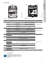
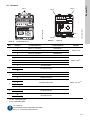
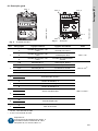
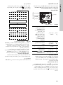
Grundfos MP 204 Installation And Operating Instructions Manual
- Tip
- Installation And Operating Instructions Manual

MP 204
Installation and operating instructions
GRUNDFOS INSTRUCTIONS
Installation and operating instructions
Other languages
net.grundfos.com/qr/i/96650480

2

3
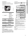
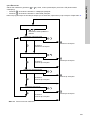
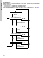
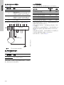
Table of contents
MP 204
English (GB)
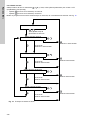
Installation and operating instructions. . . . . . . . . . . . . . . . . . . . . . . . . . . . . . . . . 5
(BG)
. . . . . . . . . . . . . . . . . . . . . . . . . . . . . . . 28
eština (CZ)
Montážní a provozní návod. . . . . . . . . . . . . . . . . . . . . . . . . . . . . . . . . . . . . . . . 51
Deutsch (DE)
Montage- und Betriebsanleitung . . . . . . . . . . . . . . . . . . . . . . . . . . . . . . . . . . . . 74
Dansk (DK)
Monterings- og driftsinstruktion. . . . . . . . . . . . . . . . . . . . . . . . . . . . . . . . . . . . . 97
Eesti (EE)
Paigaldus- ja kasutusjuhend . . . . . . . . . . . . . . . . . . . . . . . . . . . . . . . . . . . . . . 120
Español (ES)
Instrucciones de instalación y funcionamiento . . . . . . . . . . . . . . . . . . . . . . . . 143
Suomi (FI)
Asennus- ja käyttöohjeet. . . . . . . . . . . . . . . . . . . . . . . . . . . . . . . . . . . . . . . . . 166
Français (FR)
Notice d'installation et de fonctionnement. . . . . . . . . . . . . . . . . . . . . . . . . . . . 189
(GR)
. . . . . . . . . . . . . . . . . . . . . . . . . . . . . . 212
Hrvatski (HR)
Montažne i pogonske upute . . . . . . . . . . . . . . . . . . . . . . . . . . . . . . . . . . . . . . 235
Magyar (HU)
Telepítési és üzemeltetési utasítás. . . . . . . . . . . . . . . . . . . . . . . . . . . . . . . . . 258
Italiano (IT)
Istruzioni di installazione e funzionamento . . . . . . . . . . . . . . . . . . . . . . . . . . . 281
Lietuviškai (LT)
rengimo ir naudojimo instrukcija . . . . . . . . . . . . . . . . . . . . . . . . . . . . . . . . . . 304
Latviešu (LV)
Uzstdšanas un ekspluatcijas instrukcija. . . . . . . . . . . . . . . . . . . . . . . . . . . 327
Nederlands (NL)
Installatie- en bedieningsinstructies . . . . . . . . . . . . . . . . . . . . . . . . . . . . . . . . 350
Polski (PL)
Instrukcja montau i eksploatacji . . . . . . . . . . . . . . . . . . . . . . . . . . . . . . . . . . 373
Português (PT)
Instruções de instalação e funcionamento . . . . . . . . . . . . . . . . . . . . . . . . . . . 396

Table of contents
4
MP 204
Român (RO)
Instruciuni de instalare i utilizare . . . . . . . . . . . . . . . . . . . . . . . . . . . . . . . . . 419
Srpski (RS)
Uputstvo za instalaciju i rad . . . . . . . . . . . . . . . . . . . . . . . . . . . . . . . . . . . . . . 442
Svenska (SE)
Monterings- och driftsinstruktion . . . . . . . . . . . . . . . . . . . . . . . . . . . . . . . . . . . 465
Slovensko (SI)
Navodila za montažo in obratovanje. . . . . . . . . . . . . . . . . . . . . . . . . . . . . . . . 488
Slovenina (SK)
Návod na montáž a prevádzku . . . . . . . . . . . . . . . . . . . . . . . . . . . . . . . . . . . . 511
Türkçe (TR)
Montaj ve kullanım kılavuzu . . . . . . . . . . . . . . . . . . . . . . . . . . . . . . . . . . . . . . 534
(UA)
. . . . . . . . . . . . . . . . . . . . . . . . . . . . . . 557
中文 (CN)
安装和使用说明书 . . . . . . . . . . . . . . . . . . . . . . . . . . . . . . . . . . . . . . . . . . . . . . 580
(AR)
. . . . . . . . . . . . . . . . . . . . . . . . . . . . . . . . . . . . . 626
Appendix. . . . . . . . . . . . . . . . . . . . . . . . . . . . . . . . . . . . . . . . . . . . . . . . . . . . . 627

English (GB)
5
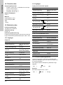
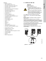
English (GB) Installation and operating instructions
Original installation and operating instructions
These installation and operating instructions
describe Grundfos MP 204.
Sections 1-15 provide important information about
the product, information necessary to be able to
unpack, install and start up the product in a safe way.
Sections 16-17 provide important information on fault
finding and disposal of the product.
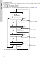
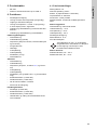
CONTENTS
Page
1. General information
The symbols and hazard statements below may
appear in Grundfos installation and operating
instructions, safety instructions and service
instructions.
1.1 Hazard statements
The symbols and hazard statements below may
appear in Grundfos installation and operating
instructions, safety instructions and service
instructions.
1. General information
5
1.1 Hazard statements
5
2. Product introduction
6
2.1 Intended use
6
2.2 Features
6
2.3 Applications
6
3. Receiving the product
6
3.1 Transporting the product
6
4. Nameplates
6
5. Product range
7
6. Functions
7
6.1 Factory settings
7
7. Mechanical installation
8
7.1 MP 204 in control cabinet
8
7.2 MP 204 on DIN rail
8
8. Electrical connection
9
8.1 Overview
10
8.2 Input for Pt100/Pt1000
11
8.3 Input for PTC/thermal switch
11
8.4 Backup fuses
11
8.5 Wiring diagrams
12
8.6 External current transformers
15
9. Startup
16
9.1 Operation
16
9.2 Setting on operating panel
17
9.3 Learning function
19
10. Grundfos GO Remote
19
10.1 Infrared communication
19
10.2 Communication
19
10.3 Grundfos GO Remote menus
19
11. MP 204 with GENIbus
20
12. Pump operation with MP 204
21
12.1 Industrial pumps
21
12.2 Submersible pumps
21
12.3 Wastewater pumps
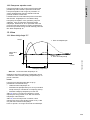
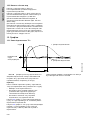
21
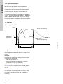
13. Curves
22
13.1 Trip class "P"
22
13.2 IEC trip curves
23
14. Technical data
24
15. Electrical data
24
15.1 Outputs
24
15.2 Inputs
24
15.3 Insulation measurement method
24
15.4 Measuring ranges
25
15.5 Setting ranges
25
16. Fault finding
26
16.1 Warning and trip codes
26
16.2 Fault finding the product
27
17. Disposing of the product
27
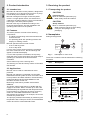
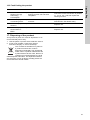
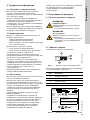
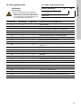
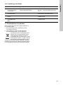
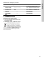
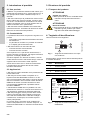
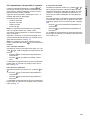
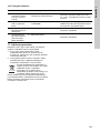
Read this document before installing the
product. Installation and operation must
comply with local regulations and accepted
codes of good practice.
This appliance can be used by children
aged from 8 years and above and persons
with reduced physical, sensory or mental
capabilities or lack of experience and
knowledge if they have been given
supervision or instruction concerning use
of the appliance in a safe way and
understand the hazards involved.
Children shall not play with the appliance.
Cleaning and user maintenance shall not
be made by children without supervision.

English (GB)
6
2. Product introduction
2.1 Intended use
MP 204 is an electronic motor protector, designed for
the protection of an asynchronous motor or a pump.
It must always be installed in a cabinet.
MP 204 is designed for single- and three-phase
motors. In single-phase motors, the start and run
capacitors are also measured. Cos is measured in
both single- and three-phase systems.
MP 204 must only be installed according to the
technical specifications. See the installation and
operating instructions for the product.
2.2 Features
The motor protector consists of the following
components
• a cabinet incorporating instrument transformers
and electronics.
• an operating panel with operating buttons and
display for reading of data.
MP 204 operates with two sets of limits:
• a set of warning limits
• a set of trip limits.
If one or more of the warning limits are exceeded,
the motor continues to run, but the warnings will
appear in the MP 204 display.
If one of the trip limits is exceeded, the trip relay
stops the motor. At the same time, the signal relay is
operating to indicate that the limit has been
exceeded.
Some values only have a warning limit.
The warning can also be read by means of Grundfos
GO Remote.
2.3 Applications
MP 204 can be used as a stand-alone motor
protector.
MP 204 may also be incorporated in a Grundfos
Dedicated Controls system in which it functions as a
motor protector and data collection unit transmitting
measured values via Grundfos GENIbus to the
Grundfos CU 362 control unit.
Monitoring of MP 204 is possible via Grundfos
GENIbus.
The power supply to MP 204 is in parallel with the
supply to the motor. Motor currents up to 120 A are
passed directly through MP 204. MP 204 protects the
motor primarily by measuring the motor current by
means of a true RMS measurement. MP 204
disconnects the contactor if, for example, the current
exceeds the preset value.
The pump is protected secondarily by measuring the
temperature with a Tempcon sensor, a Pt100/Pt1000
sensor and a PTC sensor/thermal switch.
3. Receiving the product
3.1 Transporting the product
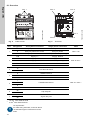
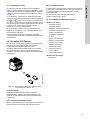
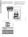
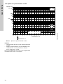
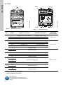
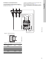
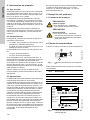
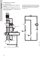
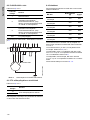
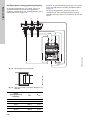
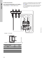
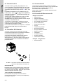
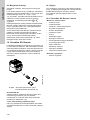
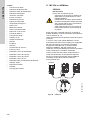
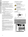
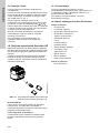
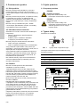
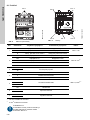
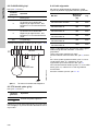
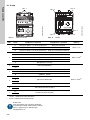
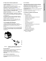
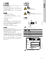
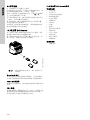
4. Nameplates
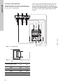
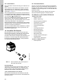
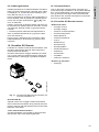
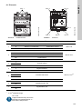
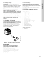
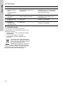
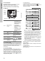
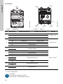
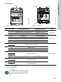
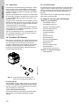
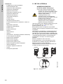
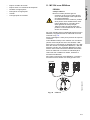
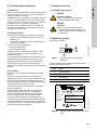
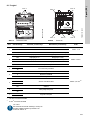
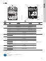
Rating and approvals.
Fig. 1 Nameplate on front cover
These four numbers must be stated when contacting
Grundfos:
Fig. 2 Nameplates on the side of MP 204
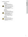
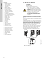
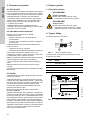
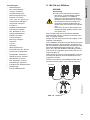
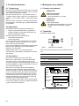
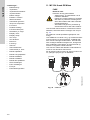
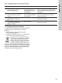
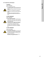
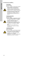
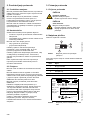
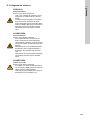
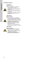
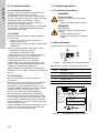
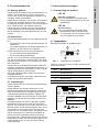
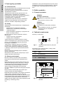
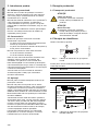
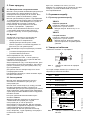
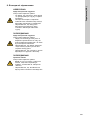
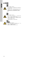
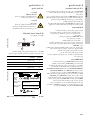
CAUTION
Falling objects
Minor or moderate personal injury
- Wear safety shoes and helmet.
CAUTION
Sharp element
Minor or moderate personal injury
- Wear protective gloves to avoid being
cut by the sharp edges of the
packaging.
TM03 1472 0806
Pos. Description
1 Product number
2 Version number
3 Serial number
4 Production code
TM07 4599 2019
Prod. No.
96079927
Serial No.
P. c .
V01
0001
0442
IP 20
2
4
1
3
MP 204 IP 20
Vin nom. 100-480 V~50/60HZ Ifuse max 160 A
Current 3-120 A~ Pint. 5 W <10kA
IEC/EN
60947
UL508
25BZ
Ta -20°C to 60°C
-20°C to 40°CTa
Type
Ic
24V 2A DC-13, L/R=40ms, 48W
400V 2A AC-15, 400VA
Pilot Duty R150=
Pilot Duty 400V 2A~
rating IEC
Relay Contact
rating UL
Relay Contact
N2042
Made in Estonia
DK-8850 Bjerringbro, Denmark
Industrial Control Equipment

English (GB)
7
5. Product range
• MP 204
• external current transformers up to 1000 A.
6. Functions
• Phase-sequence monitoring
• indication of current or temperature (user
selection)
• input for PTC/thermal switch
• indication of temperature in °C or °F (user
selection)
• 4-digit, 7-segment display
• setting and status reading with Grundfos GO
Remote
• setting and status reading via GENIbus.
Tripping conditions
• Overload
• underload (dry running)
• temperature (Tempcon sensor, PTC/thermal
switch and Pt sensor)
• missing phase
• phase sequence
• overvoltage
• undervoltage
• power factor (cos φ)
• current unbalance.
Warnings
• Overload
• underload
• temperature (Tempcon, see section
12.2 Submersible pumps, and Pt sensor)
• overvoltage
• Undervoltage
• power factor (cos φ)(in connection with single-
and three-phase connection)
• run capacitor (single-phase operation)
• start capacitor (single-phase operation)
• loss of communication in network
• harmonic distortion.
Learning function
• Phase sequence (three-phase operation)
• run capacitor (single-phase operation)
• start capacitor (single-phase operation)
• identification and measurement of Pt100/Pt1000
sensor circuit.
6.1 Factory settings
Current limit: 0 A
Nominal voltage: 400 V
Class: P (trip delay: 5 seconds)
Trip delay: 5 seconds
Number of phases: 3, non-earthed
Power-on delay: 5 seconds Learning function: Active
Active trip limits
Overload according to class
Underload: - 40 %
Overvoltage: + 20 %
Undervoltage: - 20 %
Phase-sequence monitoring
Current unbalance: 10 %
PTC/thermal switch
Active warnings
Run capacitor, low: - 50 %
Start capacitor, low: - 50 %
The overvoltage and undervoltage trip
limits are deactivated automatically if the
temperature monitoring with Tempcon or
Pt100/Pt1000 is set to active.

English (GB)
8
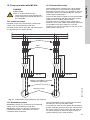
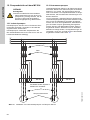
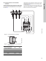
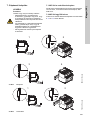
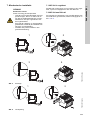
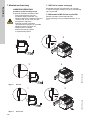
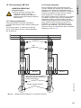
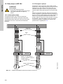
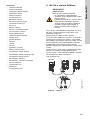
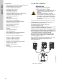
7. Mechanical installation
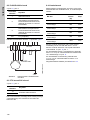
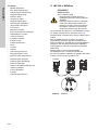
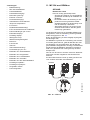
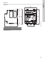
7.1 MP 204 in control cabinet
MP 204 is designed for mounting in a control
cabinet, either on a mounting plate or on a DIN rail.
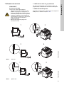
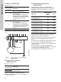
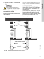
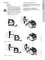
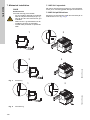
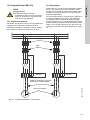
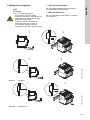
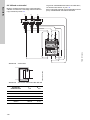
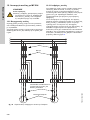
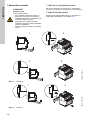
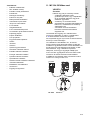
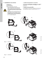
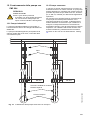
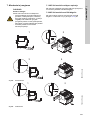
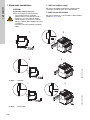
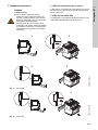
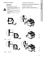
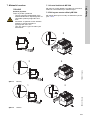
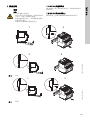
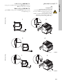
7.2 MP 204 on DIN rail
Mounting and removal of MP 204 mounted on a DIN
rail is shown in figs 3 and 4.
Fig. 3 Mounting
Fig. 4 Removal
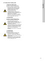
DANGER
Electric shock
Death or serious personal injury
- Before starting any work on the product,
make sure that the power supply has
been switched off and that it cannot be
accidentally switched on.
- Ensure that the sensor and power
cables are separated when installing
sensors and switches.
- Always install the product inside a
suitable cabinet.
TM03 0179 4404
34
21
TM03 0179 4404
1 2

English (GB)
9
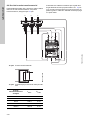
8. Electrical connection
DANGER
Electric shock
Death or serious personal injury
- All cables taken through the product
and the current transformers must be
insulated.
- Insulation between the cabinet and the
product must have a suitable insulation
resistance or the cabinet must be
connected to protective earth.
- Ensure that the trip/signal relay output
is maximum 400 V AC.
WARNING
Electric shock
Death or serious personal injury
- Before starting any work on the product,
make sure that the power supply has
been switched off and that it cannot be
accidentally switched on.
- Ensure that the power and sensor
cables are separated when mounting
the relay output connections.
- Make sure that the wiring polarity
matches the installation instructions.
WARNING
Cause of fire
Death or serious personal injury
- The product must not be supplied with
pump voltage if it exceeds the rating
mentioned on the nameplate.
- Ensure that the branch circuit fuse is
maximum 8 A.

English (GB)
10
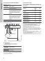
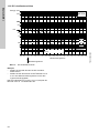
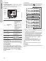
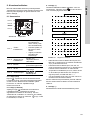
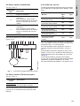
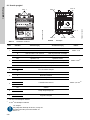
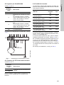
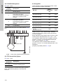
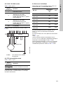
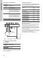
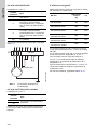
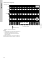
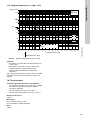
8.1 Overview
Fig. 5 Cable entries
Fig. 6 Terminals
*
10 mm
2
with cable terminal
**
4 mm
2
with cable terminal
TM03 0181 4404
Pos. 1
TM03 0181 4505
MP 204
Pos. 2
Pos. 3
Pos. 6Pos. 4 Pos. 5
Pos. 7
Pos. Designation Three-phase connection Single-phase connection Cable
1
I1 Entry for phase L1 to motor Entry for neutral
Max. ∅16I2 Entry for phase L2 to motor Entry for phase
I3 Entry for phase L3 to motor Entry for auxiliary winding
2
L1/N Supply: L1 Supply: Neutral
Max. 6 mm
2 *
L2/L Supply: L2 Supply: Phase
L3/A Supply: L3 Auxiliary winding
FE Functional earth
5 Insulation measurement
3
T1
PTC/thermal switch
Max. 2.5 mm
2 **
T2
4
A GENIbus data A
Y Reference/screen
B GENIbus data B
5
+
Pt100/Pt1000 sensorC
C
SH Screen
6
95
Trip relay NC
96
7
97
Signal relay NO
98
UL requirement.
For field wiring terminals, minimum 60/75
°C stranded copper conductors must be
used.

English (GB)
11
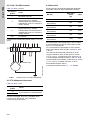
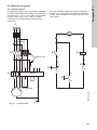
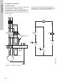
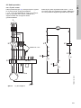
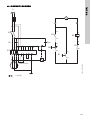
8.2 Input for Pt100/Pt1000
See fig. 6, pos. 5.
For examples of Pt100/Pt1000 connection, see figs 7
and 8.
Fig. 7 Two-core Pt100/Pt1000 connection
8.3 Input for PTC/thermal switch
See fig. 6, pos. 3.
If not used, short-circuit the PTC input using a wire,
or deactivate it with Grundfos GO Remote.
8.4 Backup fuses
Maximum backup fuse sizes which may be used for
MP 204 appear from the table below:
At motor currents up to and including 120 A, the
cables to the motor can be taken directly through the
L1-L2-L3 of MP 204.
At motor currents above 120 A, current transformers
must be used. See fig. 5, pos. 1.
If backup fuses above 50 A are used, the L1-L2-L3
and "5" to MP 204 must be protected separately with
maximum 10 A fuses. See fig. 8.
If current transformers are used, the L1-L2-L3 and
"5" to MP 204 must be protected with maximum 10 A
fuses.
For installation examples, see figs 8 to 12.
Terminal
designation
Description
+ Resistance input.
C
Correction for conductor
resistance.
To be connected by means of a
three-core Pt100/Pt1000
connection, otherwise the two "C"
terminals are to be short-circuited.
C
Correction for conductor
resistance.
To be connected by means of a
three-core Pt100/Pt1000
connection, otherwise the two "C"
terminals are to be short-circuited.
SH 0 V (screen).
TM03 1397 2205
Terminal
designation
Description
T1
Connection of PTC/thermal switch
T2
Pt100
E1
L1
L2
L3
+
C
C
I1
I2
I3
T1
T2
FE
5
A
Y
B
MP 204
Pt100/Pt1000
MP 204
Maximum size
[A]
Type
Without external current
transformer
120 RK5
With 200/5 external
current transformer
200 RK5
With 300/5 external
current transformer
300 RK5
With 500/5 external
current transformer
500 RK5
With 750/5 external
current transformer
750 RK5
With 1000/5 external
current transformer
1000 RK5

English (GB)
12
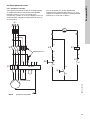
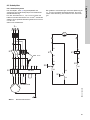
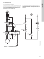
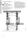
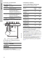
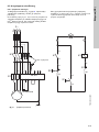
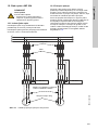
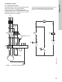
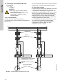
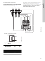
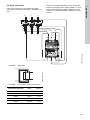
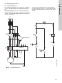
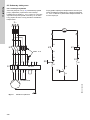
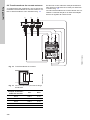
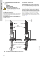
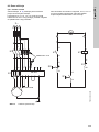
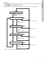
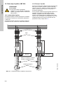
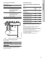
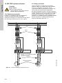
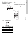
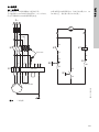
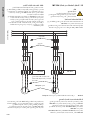
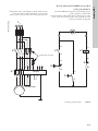
8.5 Wiring diagrams
8.5.1 Three-phase system
The wiring diagram, fig. 8, shows an example of a
three-phase pump with insulation measurement.
The connections to L1, L2, L3 and "5" can be made
with a cable of up to 10 mm
2
. A special fuse unit up
to approximately 50 A is therefore not required.
If larger backup fuses are used, the voltage to the
L1, L2 and L3 must be protected separately. We
recommend a maximum of 10 A or less.
Fig. 8 Three-phase connection
TM03 0122 2205
1
2
35
46
13
14
S1
K1
S0
22
21
13
14
K1
96
95
E1
K1
A1
A2
L
1
L
2
L
3
3
~
Pt100
E1
L1
L2
L3
+
C
C
I1
I2
I3
T1
T2
FE
5
A
Y
B
Maximum 10 A
MP 204
Pt100/Pt1000

English (GB)
13
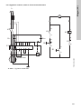
8.5.2 Three-phase system with external current transformers
Fig. 9 Three-phase connection with current transformers
Fig. 10 Five windings per phase through MP 204
TM03 0123 2205
1
2
35
46
K1
13
14
S1
K1
S0
22
21
13
14
R1
96
95
E1
A1
A2
+
C
C
T1
T2
FE
Pt100
E1
L1
L2
L3
I1
I2
I3
5
A
Y
B
L
1
L
2
L
3
3
~
Maximum 10 A
MP 204
Pt100/Pt1000
TM03 1398 1905

English (GB)
14
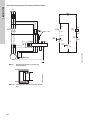
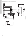
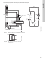
8.5.3 Single-phase system with start and run capacitors
Fig. 11 Single-phase connection
TM03 0124 2205
1
2
3
4
13
14
S1
K1
S0
22
21
13
14
K1
96
95
E1
K1
E1
L1
L2
L3
+
C
C
I1
I2
I3
T1
T2
FE
5
A
Y
B
A1
A2
MA
Pt100
CC
L
1
N
1
~
run
start
MP 204
Pt100/Pt1000

English (GB)
15
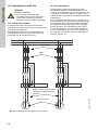
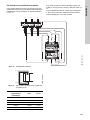
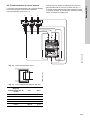
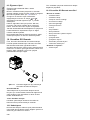
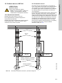
8.6 External current transformers
At motor currents above 120 A, external current
transformers must be used. Fit the transformers as
shown in fig. 12.
Take the three measuring cables through the three
holes in MP 204 five times per phase. See fig. 13.
The three current transformers must be fitted in the
same direction, and the measuring cables must be
connected in the same way.
Fig. 12 Current transformers
Fig. 13 Five windings per phase through MP 204
TM03 0172 4304
TM03 1398 1905
Current transformer
ratio
I
max.
P
max.
200:5 200 A 5 VA
300:5 300 A 5 VA
500:5 500 A 5 VA
750:5 750 A 5 VA
1000:5 1000 A 5 VA
x5
x5
x5
L
1
L
2
L
3

English (GB)
16
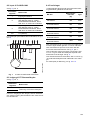
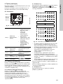
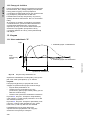
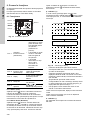
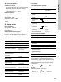
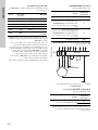
9. Startup
A basic setting of MP 204 can be made on the
operating panel.
Additional functions must be set with Grundfos GO
Remote or PC Tool Water Utility.
9.1 Operation
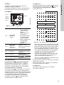
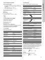
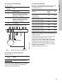
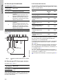
Fig. 14 Operating panel
9.1.1 Button (Test)
Press the button to open trip relay connection
95-96 and close signal relay connection 97-98. The
red "Trip" indicator light is on. The function is
identical to the overload trip.
9.1.2 Button (Reset)
Press the button to change the tripped state to
normal state with trip relay connection 95-96 closed
and signal relay connection 97-98 open. The red
"Trip" indicator light is off. This implies that the
tripped state has actually ceased. The button
also resets warnings, if any.
9.1.3 Button (+)
Normally the actual current or temperature appears
on the display. Press the button to show
information on the display, according to the following
sequence:
Fig. 15 Sequence on the display
• The trip code only appears if MP 204 has tripped.
Switches between "trip" and trip code.
• The warning code only appears if the limit value
of one or more warnings has been exceeded, and
if warning code indication has been activated.
• Temperatures only appear if the matching
sensors have been connected and activated. If
no Tempcon signal is received, "----" appears on
the MP 204 display.
•Cos φ only appears if this menu has been
enabled with Grundfos GO Remote.
When the motor is operating, the display shows the
actual value.
When the motor stops, the display shows the last
measured value.
9.1.4 Button (-)
Only used in connection with the basic setting of MP
204.
TM03 0181 4404
Pos. 1
"Power"
indicator light
• Flashes green until
MP 204 is ready for
operation (power-on
delay).
• Is permanently
green when MP 204
is ready for
operation.
• Flashes red when
communicating with
Grundfos GO
Remote.
Pos. 2
"Trip" indicator
light
Is red when the trip
relay is activated.
Pos. 3 Display
4 digits, for basic
setting and data
reading.
Pos. 4 IR field
Grundfos GO Remote
communication.
Pos. 5
Operating
buttons
Setting and operation.
MP 204
Pos. 1
Pos. 2
Pos. 4
Pos. 2
Pos. 5
Pos. 3
R
R
R
x5
x5
x5
L
1
L
2
L
3
Trip code (flashing)
Warning code no. 1-n
Current
Voltage
Temperature Tempcon
Temperature Pt sensor
Phase angle cos

English (GB)
17
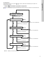
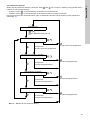
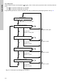
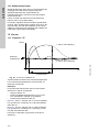
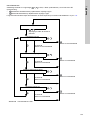
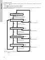
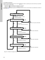
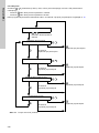
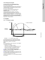
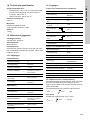
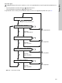
9.2 Setting on operating panel
Press the and buttons simultaneously for a
minimum of 5 seconds to open the programming
mode. When the display shows three dots, the
buttons can be released.
The set value, e.g. "4.9 A", appears. The unit symbol
"A" is flashing.
Enter these values:
• rated current
• nominal voltage
• trip class
• number of phases.
Note: Insulation measurement is only possible of
earthed three-phase systems.
If no buttons are activated, the voltage appears after
10 seconds.
After an additional 10 seconds, the set voltage is
stored automatically, and the programming mode
ends. See fig. 16.
Note: Changes in rated current must be finished by
pressing to store the change.
9.2.1 Rated current
Set the rated motor current with the and
buttons. See the motor nameplate.
• Press to store the setting and continue.
• Press to cancel the change and finish.
The programming mode ends automatically after 10
seconds, and the change is cancelled. See fig. 16.
9.2.2 Nominal voltage
Set the nominal voltage with the and buttons.
• Press to store the setting and continue.
• Press to store the setting and finish.
The programming mode ends automatically after 10
seconds, and the change is stored. See fig. 16.
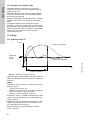
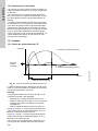
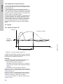
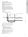
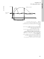
9.2.3 Trip class
Set the trip class with the and buttons.
For submersible pumps, manual setting of the trip
delay, class "P", is normally selected. The time is
factory-set to 10 seconds. It can be changed with
Grundfos GO Remote.
For other pumps, the required IEC trip class (1-45) is
to be set. Normally class 10 is selected. For trip
curves, see page 23.
• Press to store the setting and continue.
• Press to store the setting and finish.
The programming mode ends automatically after 10
seconds, and the change is stored. See fig. 16.
R
R
R

English (GB)
18
9.2.4 Number of phases
Set the number of phases with the and buttons (1 phase, 3 phases (non-earthed) or 3 phases with FE
(functional earth)).
• Press to store the setting and continue.
• Press to store the setting and finish.
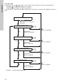
The programming mode ends automatically after 10 seconds, and the change is stored. See fig. 16.
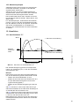
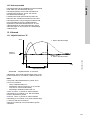
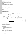
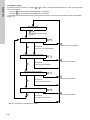
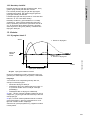
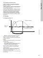
Fig. 16 Example of basic setting
R
Status display
Set rated current
Set nominal voltage
Set trip class
+
Set number of phases
Press and hold for
approximately 5 seconds
10 seconds
10 seconds
The value is stored
10 seconds
The value is stored
10 seconds
The value is stored
R
The value is stored
R
The value is not stored
R
The value is stored
R
The value is stored
The value is not stored

English (GB)
19
9.3 Learning function
The learning function is factory-set to "Enabled".
After 2 minutes of continuous motor operation, "LRN"
appears on the display for approximately 5 seconds,
while the values are being stored in MP 204. See fig.
14, pos. 3.
If, for instance, a Pt sensor or capacitor has been
replaced, reactivate the learning function by pressing
the and buttons for a minimum of 10 seconds.
The dot in the right side of the display is flashing. MP
204 is waiting for current to pass through the unit for
a minimum of 120 seconds. Then the phase
sequence is measured and stored.
In single-phase systems, MP 204 measures the
capacity of the start and run capacitors and stores
the values as reference.
If a Pt100/Pt1000 sensor is installed, the cable
impedances to the sensor are measured and stored
as reference.
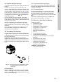
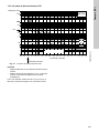
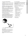
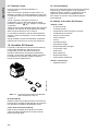
10. Grundfos GO Remote
The product is designed for infrared communication
with Grundfos GO Remote. MP 204 must be
configured using Grundfos GO Remote.
Grundfos GO Remote enables setting of functions
and gives access to status overviews, technical
product information, alarm logs and actual operating
parameters.
Fig. 17 Grundfos GO Remote communication
via infrared connection, IR
Grundfos MI 301
Separate module enabling radio or infrared
communication. Use the module together with an
Android or iOS-based smart device with Bluetooth
connection.
10.1 Infrared communication
When communicating via infrared light, Grundfos GO
Remote must be pointed at the operating panel.
10.2 Communication
If a Grundfos Communication Interface Unit (CIU) is
to be used, we recommend you to fit it according to
the wiring diagram and layout supplied with the
Control MP 204.
All variants can be extended with external
communication as an option.
10.3 Grundfos GO Remote menus
"Status and limits"
• "Average current"
• "Average voltage"
• "Tempcon motor temperature"
• "Pt sensor temperature"
• "Current unbalance"
• "Insulation resistance"
•"Cos "
• "Power consumption"
• "Energy consumption"
• "Energy trip counter"
• "Phase information"
• "Operating hours"
• "Number of starts"
• "Trip counter"
• "Harmonic distortion"
"Alarms and warnings"
• "Alarm log"
TM07 4665 2119
R
+

English (GB)
20
"Settings"
• "Mains connection"
• "Trip IEC class"
• "Trip class delay"
• "Trip delay"
• "Rated voltage"
• "External CT factor"
• "Power-on delay"
• "Automatic restarting"
• "Tempcon temperature"
• "PT sensor"
• "Insulation measurement"
• "PTC sensor/thermal switch"
• "Restarts per 24 hours"
• "Display units"
• "Display setup"
• "Show cos "
• "Show warning"
• "Number"
• "Learning"
•"Service"
• "Service warning"
• "Starts per hour"
• "Reset trip counter"
• "Reset energy counter"
• "Reset start counter"
• "Reset hours counter"
• "Reset all trip counters"
• "Store settings"
• "Recall settings"
• "Undo"
• "Unit configuration"
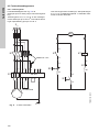
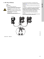
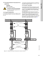
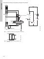
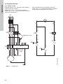
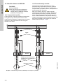
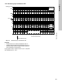
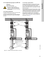
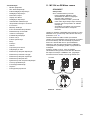
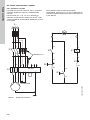
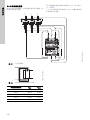
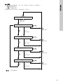
11. MP 204 with GENIbus
If several MP 204 units are connected to the same
GENIbus, the connection is to be made as shown in
fig. 18.
Leave the screen as close to the conductive support
as possible.
If GENIbus has been in use, and bus communication
monitoring has been activated, MP 204 continues to
monitor the bus activity. If MP 204 does not receive
GENIbus telegrams, MP 204 presumes that the
GENIbus connection has been disconnected and
indicates a fault on the individual units.
Each of the units in the chain must be assigned an
identification number with Grundfos GO Remote.
For further information about GENIbus, see
Grundfos Product Center at www.grundfos.com.
Fig. 18 GENIbus
DANGER
Electric shock
Death or serious personal injury
- Ensure that the sensor and power
cables are separated when installing
GENIbus.
- Insulation between the cabinet and the
product must have a suitable insulation
resistance or the cabinet must be
connected to protective earth.
- All cables taken through the product
and the current transformers must be
insulated.
TM05 1096 2111
MP 204 MP 204
AYB
C
C
SH
T
R
95 96 97
98
AYB
C
C
CC
SH
95 96 97
98
Power PowerTrip Trip
L1/N
L2/L
L3/A FG
5
L1/N
L2/L
L3/A FG
5
T1
T2
T1
T2
A
Y
B
CU 361
CU 362
Pagina se încarcă...
Pagina se încarcă...
Pagina se încarcă...
Pagina se încarcă...
Pagina se încarcă...
Pagina se încarcă...
Pagina se încarcă...
Pagina se încarcă...
Pagina se încarcă...
Pagina se încarcă...
Pagina se încarcă...
Pagina se încarcă...
Pagina se încarcă...
Pagina se încarcă...
Pagina se încarcă...
Pagina se încarcă...
Pagina se încarcă...
Pagina se încarcă...
Pagina se încarcă...
Pagina se încarcă...
Pagina se încarcă...
Pagina se încarcă...
Pagina se încarcă...
Pagina se încarcă...
Pagina se încarcă...
Pagina se încarcă...
Pagina se încarcă...
Pagina se încarcă...
Pagina se încarcă...
Pagina se încarcă...
Pagina se încarcă...
Pagina se încarcă...
Pagina se încarcă...
Pagina se încarcă...
Pagina se încarcă...
Pagina se încarcă...
Pagina se încarcă...
Pagina se încarcă...
Pagina se încarcă...
Pagina se încarcă...
Pagina se încarcă...
Pagina se încarcă...
Pagina se încarcă...
Pagina se încarcă...
Pagina se încarcă...
Pagina se încarcă...
Pagina se încarcă...
Pagina se încarcă...
Pagina se încarcă...
Pagina se încarcă...
Pagina se încarcă...
Pagina se încarcă...
Pagina se încarcă...
Pagina se încarcă...
Pagina se încarcă...
Pagina se încarcă...
Pagina se încarcă...
Pagina se încarcă...
Pagina se încarcă...
Pagina se încarcă...
Pagina se încarcă...
Pagina se încarcă...
Pagina se încarcă...
Pagina se încarcă...
Pagina se încarcă...
Pagina se încarcă...
Pagina se încarcă...
Pagina se încarcă...
Pagina se încarcă...
Pagina se încarcă...
Pagina se încarcă...
Pagina se încarcă...
Pagina se încarcă...
Pagina se încarcă...
Pagina se încarcă...
Pagina se încarcă...
Pagina se încarcă...
Pagina se încarcă...
Pagina se încarcă...
Pagina se încarcă...
Pagina se încarcă...
Pagina se încarcă...
Pagina se încarcă...
Pagina se încarcă...
Pagina se încarcă...
Pagina se încarcă...
Pagina se încarcă...
Pagina se încarcă...
Pagina se încarcă...
Pagina se încarcă...
Pagina se încarcă...
Pagina se încarcă...
Pagina se încarcă...
Pagina se încarcă...
Pagina se încarcă...
Pagina se încarcă...
Pagina se încarcă...
Pagina se încarcă...
Pagina se încarcă...
Pagina se încarcă...
Pagina se încarcă...
Pagina se încarcă...
Pagina se încarcă...
Pagina se încarcă...
Pagina se încarcă...
Pagina se încarcă...
Pagina se încarcă...
Pagina se încarcă...
Pagina se încarcă...
Pagina se încarcă...
Pagina se încarcă...
Pagina se încarcă...
Pagina se încarcă...
Pagina se încarcă...
Pagina se încarcă...
Pagina se încarcă...
Pagina se încarcă...
Pagina se încarcă...
Pagina se încarcă...
Pagina se încarcă...
Pagina se încarcă...
Pagina se încarcă...
Pagina se încarcă...
Pagina se încarcă...
Pagina se încarcă...
Pagina se încarcă...
Pagina se încarcă...
Pagina se încarcă...
Pagina se încarcă...
Pagina se încarcă...
Pagina se încarcă...
Pagina se încarcă...
Pagina se încarcă...
Pagina se încarcă...
Pagina se încarcă...
Pagina se încarcă...
Pagina se încarcă...
Pagina se încarcă...
Pagina se încarcă...
Pagina se încarcă...
Pagina se încarcă...
Pagina se încarcă...
Pagina se încarcă...
Pagina se încarcă...
Pagina se încarcă...
Pagina se încarcă...
Pagina se încarcă...
Pagina se încarcă...
Pagina se încarcă...
Pagina se încarcă...
Pagina se încarcă...
Pagina se încarcă...
Pagina se încarcă...
Pagina se încarcă...
Pagina se încarcă...
Pagina se încarcă...
Pagina se încarcă...
Pagina se încarcă...
Pagina se încarcă...
Pagina se încarcă...
Pagina se încarcă...
Pagina se încarcă...
Pagina se încarcă...
Pagina se încarcă...
Pagina se încarcă...
Pagina se încarcă...
Pagina se încarcă...
Pagina se încarcă...
Pagina se încarcă...
Pagina se încarcă...
Pagina se încarcă...
Pagina se încarcă...
Pagina se încarcă...
Pagina se încarcă...
Pagina se încarcă...
Pagina se încarcă...
Pagina se încarcă...
Pagina se încarcă...
Pagina se încarcă...
Pagina se încarcă...
Pagina se încarcă...
Pagina se încarcă...
Pagina se încarcă...
Pagina se încarcă...
Pagina se încarcă...
Pagina se încarcă...
Pagina se încarcă...
Pagina se încarcă...
Pagina se încarcă...
Pagina se încarcă...
Pagina se încarcă...
Pagina se încarcă...
Pagina se încarcă...
Pagina se încarcă...
Pagina se încarcă...
Pagina se încarcă...
Pagina se încarcă...
Pagina se încarcă...
Pagina se încarcă...
Pagina se încarcă...
Pagina se încarcă...
Pagina se încarcă...
Pagina se încarcă...
Pagina se încarcă...
Pagina se încarcă...
Pagina se încarcă...
Pagina se încarcă...
Pagina se încarcă...
Pagina se încarcă...
Pagina se încarcă...
Pagina se încarcă...
Pagina se încarcă...
Pagina se încarcă...
Pagina se încarcă...
Pagina se încarcă...
Pagina se încarcă...
Pagina se încarcă...
Pagina se încarcă...
Pagina se încarcă...
Pagina se încarcă...
Pagina se încarcă...
Pagina se încarcă...
Pagina se încarcă...
Pagina se încarcă...
Pagina se încarcă...
Pagina se încarcă...
Pagina se încarcă...
Pagina se încarcă...
Pagina se încarcă...
Pagina se încarcă...
Pagina se încarcă...
Pagina se încarcă...
Pagina se încarcă...
Pagina se încarcă...
Pagina se încarcă...
Pagina se încarcă...
Pagina se încarcă...
Pagina se încarcă...
Pagina se încarcă...
Pagina se încarcă...
Pagina se încarcă...
Pagina se încarcă...
Pagina se încarcă...
Pagina se încarcă...
Pagina se încarcă...
Pagina se încarcă...
Pagina se încarcă...
Pagina se încarcă...
Pagina se încarcă...
Pagina se încarcă...
Pagina se încarcă...
Pagina se încarcă...
Pagina se încarcă...
Pagina se încarcă...
Pagina se încarcă...
Pagina se încarcă...
Pagina se încarcă...
Pagina se încarcă...
Pagina se încarcă...
Pagina se încarcă...
Pagina se încarcă...
Pagina se încarcă...
Pagina se încarcă...
Pagina se încarcă...
Pagina se încarcă...
Pagina se încarcă...
Pagina se încarcă...
Pagina se încarcă...
Pagina se încarcă...
Pagina se încarcă...
Pagina se încarcă...
Pagina se încarcă...
Pagina se încarcă...
Pagina se încarcă...
Pagina se încarcă...
Pagina se încarcă...
Pagina se încarcă...
Pagina se încarcă...
Pagina se încarcă...
Pagina se încarcă...
Pagina se încarcă...
Pagina se încarcă...
Pagina se încarcă...
Pagina se încarcă...
Pagina se încarcă...
Pagina se încarcă...
Pagina se încarcă...
Pagina se încarcă...
Pagina se încarcă...
Pagina se încarcă...
Pagina se încarcă...
Pagina se încarcă...
Pagina se încarcă...
Pagina se încarcă...
Pagina se încarcă...
Pagina se încarcă...
Pagina se încarcă...
Pagina se încarcă...
Pagina se încarcă...
Pagina se încarcă...
Pagina se încarcă...
Pagina se încarcă...
Pagina se încarcă...
Pagina se încarcă...
Pagina se încarcă...
Pagina se încarcă...
Pagina se încarcă...
Pagina se încarcă...
Pagina se încarcă...
Pagina se încarcă...
Pagina se încarcă...
Pagina se încarcă...
Pagina se încarcă...
Pagina se încarcă...
Pagina se încarcă...
Pagina se încarcă...
Pagina se încarcă...
Pagina se încarcă...
Pagina se încarcă...
Pagina se încarcă...
Pagina se încarcă...
Pagina se încarcă...
Pagina se încarcă...
Pagina se încarcă...
Pagina se încarcă...
Pagina se încarcă...
Pagina se încarcă...
Pagina se încarcă...
Pagina se încarcă...
Pagina se încarcă...
Pagina se încarcă...
Pagina se încarcă...
Pagina se încarcă...
Pagina se încarcă...
Pagina se încarcă...
Pagina se încarcă...
Pagina se încarcă...
Pagina se încarcă...
Pagina se încarcă...
Pagina se încarcă...
Pagina se încarcă...
Pagina se încarcă...
Pagina se încarcă...
Pagina se încarcă...
Pagina se încarcă...
Pagina se încarcă...
Pagina se încarcă...
Pagina se încarcă...
Pagina se încarcă...
Pagina se încarcă...
Pagina se încarcă...
Pagina se încarcă...
Pagina se încarcă...
Pagina se încarcă...
Pagina se încarcă...
Pagina se încarcă...
Pagina se încarcă...
Pagina se încarcă...
Pagina se încarcă...
Pagina se încarcă...
Pagina se încarcă...
Pagina se încarcă...
Pagina se încarcă...
Pagina se încarcă...
Pagina se încarcă...
Pagina se încarcă...
Pagina se încarcă...
Pagina se încarcă...
Pagina se încarcă...
Pagina se încarcă...
Pagina se încarcă...
Pagina se încarcă...
Pagina se încarcă...
Pagina se încarcă...
Pagina se încarcă...
Pagina se încarcă...
Pagina se încarcă...
Pagina se încarcă...
Pagina se încarcă...
Pagina se încarcă...
Pagina se încarcă...
Pagina se încarcă...
Pagina se încarcă...
Pagina se încarcă...
Pagina se încarcă...
Pagina se încarcă...
Pagina se încarcă...
Pagina se încarcă...
Pagina se încarcă...
Pagina se încarcă...
Pagina se încarcă...
Pagina se încarcă...
Pagina se încarcă...
Pagina se încarcă...
Pagina se încarcă...
Pagina se încarcă...
Pagina se încarcă...
Pagina se încarcă...
Pagina se încarcă...
Pagina se încarcă...
Pagina se încarcă...
Pagina se încarcă...
Pagina se încarcă...
Pagina se încarcă...
Pagina se încarcă...
Pagina se încarcă...
Pagina se încarcă...
Pagina se încarcă...
Pagina se încarcă...
Pagina se încarcă...
Pagina se încarcă...
Pagina se încarcă...
Pagina se încarcă...
Pagina se încarcă...
Pagina se încarcă...
Pagina se încarcă...
Pagina se încarcă...
Pagina se încarcă...
Pagina se încarcă...
Pagina se încarcă...
Pagina se încarcă...
Pagina se încarcă...
Pagina se încarcă...
Pagina se încarcă...
Pagina se încarcă...
Pagina se încarcă...
Pagina se încarcă...
Pagina se încarcă...
Pagina se încarcă...
Pagina se încarcă...
Pagina se încarcă...
Pagina se încarcă...
Pagina se încarcă...
Pagina se încarcă...
Pagina se încarcă...
Pagina se încarcă...
Pagina se încarcă...
Pagina se încarcă...
Pagina se încarcă...
Pagina se încarcă...
Pagina se încarcă...
Pagina se încarcă...
Pagina se încarcă...
Pagina se încarcă...
Pagina se încarcă...
Pagina se încarcă...
Pagina se încarcă...
Pagina se încarcă...
Pagina se încarcă...
Pagina se încarcă...
Pagina se încarcă...
Pagina se încarcă...
Pagina se încarcă...
Pagina se încarcă...
Pagina se încarcă...
Pagina se încarcă...
Pagina se încarcă...
Pagina se încarcă...
Pagina se încarcă...
Pagina se încarcă...
Pagina se încarcă...
Pagina se încarcă...
Pagina se încarcă...
Pagina se încarcă...
Pagina se încarcă...
Pagina se încarcă...
Pagina se încarcă...
Pagina se încarcă...
Pagina se încarcă...
Pagina se încarcă...
Pagina se încarcă...
Pagina se încarcă...
Pagina se încarcă...
Pagina se încarcă...
Pagina se încarcă...
Pagina se încarcă...
Pagina se încarcă...
Pagina se încarcă...
Pagina se încarcă...
Pagina se încarcă...
Pagina se încarcă...
Pagina se încarcă...
Pagina se încarcă...
Pagina se încarcă...
Pagina se încarcă...
Pagina se încarcă...
Pagina se încarcă...
Pagina se încarcă...
Pagina se încarcă...
Pagina se încarcă...
Pagina se încarcă...
Pagina se încarcă...
Pagina se încarcă...
Pagina se încarcă...
Pagina se încarcă...
Pagina se încarcă...
Pagina se încarcă...
Pagina se încarcă...
Pagina se încarcă...
Pagina se încarcă...
Pagina se încarcă...
Pagina se încarcă...
Pagina se încarcă...
Pagina se încarcă...
Pagina se încarcă...
Pagina se încarcă...
Pagina se încarcă...
Pagina se încarcă...
Pagina se încarcă...
Pagina se încarcă...
Pagina se încarcă...
Pagina se încarcă...
Pagina se încarcă...
Pagina se încarcă...
Pagina se încarcă...
Pagina se încarcă...
Pagina se încarcă...
Pagina se încarcă...
Pagina se încarcă...
Pagina se încarcă...
Pagina se încarcă...
Pagina se încarcă...
Pagina se încarcă...
Pagina se încarcă...
Pagina se încarcă...
Pagina se încarcă...
Pagina se încarcă...
Pagina se încarcă...
Pagina se încarcă...
Pagina se încarcă...
Pagina se încarcă...
Pagina se încarcă...
Pagina se încarcă...
Pagina se încarcă...
Pagina se încarcă...
Pagina se încarcă...
Pagina se încarcă...
Pagina se încarcă...
Pagina se încarcă...
Pagina se încarcă...
Pagina se încarcă...
Pagina se încarcă...
Pagina se încarcă...
Pagina se încarcă...
Pagina se încarcă...
Pagina se încarcă...
Pagina se încarcă...
Pagina se încarcă...
Pagina se încarcă...
Pagina se încarcă...
Pagina se încarcă...
Pagina se încarcă...
Pagina se încarcă...
Pagina se încarcă...
Pagina se încarcă...
Pagina se încarcă...
Pagina se încarcă...
Pagina se încarcă...
Pagina se încarcă...
Pagina se încarcă...
Pagina se încarcă...
Pagina se încarcă...
Pagina se încarcă...
Pagina se încarcă...
Pagina se încarcă...
Pagina se încarcă...
Pagina se încarcă...
Pagina se încarcă...
Pagina se încarcă...
Pagina se încarcă...
Pagina se încarcă...
Pagina se încarcă...
Pagina se încarcă...
Pagina se încarcă...
Pagina se încarcă...
Pagina se încarcă...
Pagina se încarcă...
Pagina se încarcă...
Pagina se încarcă...
Pagina se încarcă...
Pagina se încarcă...
Pagina se încarcă...
Pagina se încarcă...
Pagina se încarcă...
Pagina se încarcă...
Pagina se încarcă...
Pagina se încarcă...
Pagina se încarcă...
Pagina se încarcă...
Pagina se încarcă...
Pagina se încarcă...
Pagina se încarcă...
Pagina se încarcă...
Pagina se încarcă...
Pagina se încarcă...
Pagina se încarcă...
Pagina se încarcă...
Pagina se încarcă...
Pagina se încarcă...
Pagina se încarcă...
Pagina se încarcă...
Pagina se încarcă...
Pagina se încarcă...
Pagina se încarcă...
Pagina se încarcă...
Pagina se încarcă...
Pagina se încarcă...
Pagina se încarcă...
Pagina se încarcă...
Pagina se încarcă...
Pagina se încarcă...
Pagina se încarcă...
-
 1
1
-
 2
2
-
 3
3
-
 4
4
-
 5
5
-
 6
6
-
 7
7
-
 8
8
-
 9
9
-
 10
10
-
 11
11
-
 12
12
-
 13
13
-
 14
14
-
 15
15
-
 16
16
-
 17
17
-
 18
18
-
 19
19
-
 20
20
-
 21
21
-
 22
22
-
 23
23
-
 24
24
-
 25
25
-
 26
26
-
 27
27
-
 28
28
-
 29
29
-
 30
30
-
 31
31
-
 32
32
-
 33
33
-
 34
34
-
 35
35
-
 36
36
-
 37
37
-
 38
38
-
 39
39
-
 40
40
-
 41
41
-
 42
42
-
 43
43
-
 44
44
-
 45
45
-
 46
46
-
 47
47
-
 48
48
-
 49
49
-
 50
50
-
 51
51
-
 52
52
-
 53
53
-
 54
54
-
 55
55
-
 56
56
-
 57
57
-
 58
58
-
 59
59
-
 60
60
-
 61
61
-
 62
62
-
 63
63
-
 64
64
-
 65
65
-
 66
66
-
 67
67
-
 68
68
-
 69
69
-
 70
70
-
 71
71
-
 72
72
-
 73
73
-
 74
74
-
 75
75
-
 76
76
-
 77
77
-
 78
78
-
 79
79
-
 80
80
-
 81
81
-
 82
82
-
 83
83
-
 84
84
-
 85
85
-
 86
86
-
 87
87
-
 88
88
-
 89
89
-
 90
90
-
 91
91
-
 92
92
-
 93
93
-
 94
94
-
 95
95
-
 96
96
-
 97
97
-
 98
98
-
 99
99
-
 100
100
-
 101
101
-
 102
102
-
 103
103
-
 104
104
-
 105
105
-
 106
106
-
 107
107
-
 108
108
-
 109
109
-
 110
110
-
 111
111
-
 112
112
-
 113
113
-
 114
114
-
 115
115
-
 116
116
-
 117
117
-
 118
118
-
 119
119
-
 120
120
-
 121
121
-
 122
122
-
 123
123
-
 124
124
-
 125
125
-
 126
126
-
 127
127
-
 128
128
-
 129
129
-
 130
130
-
 131
131
-
 132
132
-
 133
133
-
 134
134
-
 135
135
-
 136
136
-
 137
137
-
 138
138
-
 139
139
-
 140
140
-
 141
141
-
 142
142
-
 143
143
-
 144
144
-
 145
145
-
 146
146
-
 147
147
-
 148
148
-
 149
149
-
 150
150
-
 151
151
-
 152
152
-
 153
153
-
 154
154
-
 155
155
-
 156
156
-
 157
157
-
 158
158
-
 159
159
-
 160
160
-
 161
161
-
 162
162
-
 163
163
-
 164
164
-
 165
165
-
 166
166
-
 167
167
-
 168
168
-
 169
169
-
 170
170
-
 171
171
-
 172
172
-
 173
173
-
 174
174
-
 175
175
-
 176
176
-
 177
177
-
 178
178
-
 179
179
-
 180
180
-
 181
181
-
 182
182
-
 183
183
-
 184
184
-
 185
185
-
 186
186
-
 187
187
-
 188
188
-
 189
189
-
 190
190
-
 191
191
-
 192
192
-
 193
193
-
 194
194
-
 195
195
-
 196
196
-
 197
197
-
 198
198
-
 199
199
-
 200
200
-
 201
201
-
 202
202
-
 203
203
-
 204
204
-
 205
205
-
 206
206
-
 207
207
-
 208
208
-
 209
209
-
 210
210
-
 211
211
-
 212
212
-
 213
213
-
 214
214
-
 215
215
-
 216
216
-
 217
217
-
 218
218
-
 219
219
-
 220
220
-
 221
221
-
 222
222
-
 223
223
-
 224
224
-
 225
225
-
 226
226
-
 227
227
-
 228
228
-
 229
229
-
 230
230
-
 231
231
-
 232
232
-
 233
233
-
 234
234
-
 235
235
-
 236
236
-
 237
237
-
 238
238
-
 239
239
-
 240
240
-
 241
241
-
 242
242
-
 243
243
-
 244
244
-
 245
245
-
 246
246
-
 247
247
-
 248
248
-
 249
249
-
 250
250
-
 251
251
-
 252
252
-
 253
253
-
 254
254
-
 255
255
-
 256
256
-
 257
257
-
 258
258
-
 259
259
-
 260
260
-
 261
261
-
 262
262
-
 263
263
-
 264
264
-
 265
265
-
 266
266
-
 267
267
-
 268
268
-
 269
269
-
 270
270
-
 271
271
-
 272
272
-
 273
273
-
 274
274
-
 275
275
-
 276
276
-
 277
277
-
 278
278
-
 279
279
-
 280
280
-
 281
281
-
 282
282
-
 283
283
-
 284
284
-
 285
285
-
 286
286
-
 287
287
-
 288
288
-
 289
289
-
 290
290
-
 291
291
-
 292
292
-
 293
293
-
 294
294
-
 295
295
-
 296
296
-
 297
297
-
 298
298
-
 299
299
-
 300
300
-
 301
301
-
 302
302
-
 303
303
-
 304
304
-
 305
305
-
 306
306
-
 307
307
-
 308
308
-
 309
309
-
 310
310
-
 311
311
-
 312
312
-
 313
313
-
 314
314
-
 315
315
-
 316
316
-
 317
317
-
 318
318
-
 319
319
-
 320
320
-
 321
321
-
 322
322
-
 323
323
-
 324
324
-
 325
325
-
 326
326
-
 327
327
-
 328
328
-
 329
329
-
 330
330
-
 331
331
-
 332
332
-
 333
333
-
 334
334
-
 335
335
-
 336
336
-
 337
337
-
 338
338
-
 339
339
-
 340
340
-
 341
341
-
 342
342
-
 343
343
-
 344
344
-
 345
345
-
 346
346
-
 347
347
-
 348
348
-
 349
349
-
 350
350
-
 351
351
-
 352
352
-
 353
353
-
 354
354
-
 355
355
-
 356
356
-
 357
357
-
 358
358
-
 359
359
-
 360
360
-
 361
361
-
 362
362
-
 363
363
-
 364
364
-
 365
365
-
 366
366
-
 367
367
-
 368
368
-
 369
369
-
 370
370
-
 371
371
-
 372
372
-
 373
373
-
 374
374
-
 375
375
-
 376
376
-
 377
377
-
 378
378
-
 379
379
-
 380
380
-
 381
381
-
 382
382
-
 383
383
-
 384
384
-
 385
385
-
 386
386
-
 387
387
-
 388
388
-
 389
389
-
 390
390
-
 391
391
-
 392
392
-
 393
393
-
 394
394
-
 395
395
-
 396
396
-
 397
397
-
 398
398
-
 399
399
-
 400
400
-
 401
401
-
 402
402
-
 403
403
-
 404
404
-
 405
405
-
 406
406
-
 407
407
-
 408
408
-
 409
409
-
 410
410
-
 411
411
-
 412
412
-
 413
413
-
 414
414
-
 415
415
-
 416
416
-
 417
417
-
 418
418
-
 419
419
-
 420
420
-
 421
421
-
 422
422
-
 423
423
-
 424
424
-
 425
425
-
 426
426
-
 427
427
-
 428
428
-
 429
429
-
 430
430
-
 431
431
-
 432
432
-
 433
433
-
 434
434
-
 435
435
-
 436
436
-
 437
437
-
 438
438
-
 439
439
-
 440
440
-
 441
441
-
 442
442
-
 443
443
-
 444
444
-
 445
445
-
 446
446
-
 447
447
-
 448
448
-
 449
449
-
 450
450
-
 451
451
-
 452
452
-
 453
453
-
 454
454
-
 455
455
-
 456
456
-
 457
457
-
 458
458
-
 459
459
-
 460
460
-
 461
461
-
 462
462
-
 463
463
-
 464
464
-
 465
465
-
 466
466
-
 467
467
-
 468
468
-
 469
469
-
 470
470
-
 471
471
-
 472
472
-
 473
473
-
 474
474
-
 475
475
-
 476
476
-
 477
477
-
 478
478
-
 479
479
-
 480
480
-
 481
481
-
 482
482
-
 483
483
-
 484
484
-
 485
485
-
 486
486
-
 487
487
-
 488
488
-
 489
489
-
 490
490
-
 491
491
-
 492
492
-
 493
493
-
 494
494
-
 495
495
-
 496
496
-
 497
497
-
 498
498
-
 499
499
-
 500
500
-
 501
501
-
 502
502
-
 503
503
-
 504
504
-
 505
505
-
 506
506
-
 507
507
-
 508
508
-
 509
509
-
 510
510
-
 511
511
-
 512
512
-
 513
513
-
 514
514
-
 515
515
-
 516
516
-
 517
517
-
 518
518
-
 519
519
-
 520
520
-
 521
521
-
 522
522
-
 523
523
-
 524
524
-
 525
525
-
 526
526
-
 527
527
-
 528
528
-
 529
529
-
 530
530
-
 531
531
-
 532
532
-
 533
533
-
 534
534
-
 535
535
-
 536
536
-
 537
537
-
 538
538
-
 539
539
-
 540
540
-
 541
541
-
 542
542
-
 543
543
-
 544
544
-
 545
545
-
 546
546
-
 547
547
-
 548
548
-
 549
549
-
 550
550
-
 551
551
-
 552
552
-
 553
553
-
 554
554
-
 555
555
-
 556
556
-
 557
557
-
 558
558
-
 559
559
-
 560
560
-
 561
561
-
 562
562
-
 563
563
-
 564
564
-
 565
565
-
 566
566
-
 567
567
-
 568
568
-
 569
569
-
 570
570
-
 571
571
-
 572
572
-
 573
573
-
 574
574
-
 575
575
-
 576
576
-
 577
577
-
 578
578
-
 579
579
-
 580
580
-
 581
581
-
 582
582
-
 583
583
-
 584
584
-
 585
585
-
 586
586
-
 587
587
-
 588
588
-
 589
589
-
 590
590
-
 591
591
-
 592
592
-
 593
593
-
 594
594
-
 595
595
-
 596
596
-
 597
597
-
 598
598
-
 599
599
-
 600
600
-
 601
601
-
 602
602
-
 603
603
-
 604
604
-
 605
605
-
 606
606
-
 607
607
-
 608
608
-
 609
609
-
 610
610
-
 611
611
-
 612
612
-
 613
613
-
 614
614
-
 615
615
-
 616
616
-
 617
617
-
 618
618
-
 619
619
-
 620
620
-
 621
621
-
 622
622
-
 623
623
-
 624
624
-
 625
625
-
 626
626
-
 627
627
-
 628
628
-
 629
629
-
 630
630
-
 631
631
-
 632
632


Grundfos MP 204 Installation And Operating Instructions Manual
- Tip
- Installation And Operating Instructions Manual
în alte limbi
- slovenčina: Grundfos MP 204
Lucrări înrudite
-
Grundfos MP 204 Instructions Manual
-
Grundfos 98046405 Manual de utilizare
-
-
Grundfos MI 202 Manual de utilizare
-
-
-
-
-
-
Grundfos APG.50.12.1 Installation And Operating Instructions Manual
