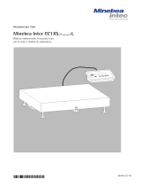
Minebea Intec YDI05-Z Interface Converter Manualul proprietarului
- Tip
- Manualul proprietarului

Operating Instructions
Minebea Intec Model YDI05-Z
Interface Converter
98647-004-09

2 YDI05-Z
2
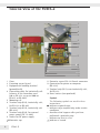
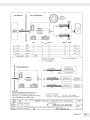
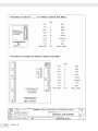
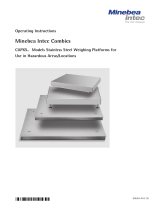
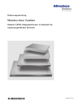
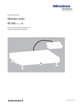
General View of the YDI05-Z
1Cover
2 Fastening screws (4 pcs)
3 Equipotential bonding terminal
(ground/earth)
4 Connecting cable for intrinsically safe
balances in the hazardous areas
(20 m, RS-232, or up to 1000 m:
RS-422 or RS-485).
5 Mounting rail
6 Terminal strip (LV2), intrinsically safe,
for RS-232 or RS-485
7 Terminal strip (LV3), intrinsically safe
(RS-422)
8 Terminal strip (LV4), for external
power source (DC 12-30V)
9 Socket for DC power supply
10 Protective cap
11 Protective cap or RS-232 female connector
12 Connection for printer or computer
(RS-232).
13 Terminal strip (LV1), non-intrinsically safe,
for RS-232
14 Zener barriers (encapsulated)
Symbols
The following symbols are used in these
instructions:
§indicates required steps
$indicates steps required only under certain
conditions
> describes what happens after you have
performed a particular step
– indicates an item in a list
!indicates a hazard
1
2
3
4
5
6
8
14
13
7
9
10
11
12
14
13

YDI05-Z 3
Contents
2 General View of the Equipment
3 Intended Use
4 Warnings and Safety Precautions
5 Getting Started
6 Operation
9 Care and Maintenance
10 Recycling
11 Specifications
12 Documents
Intended Use
The YDI05-Z interface converter is made
for installation in the non-hazardous area.
It bears the following ATEX marking:
ATEX II (2) GD [Ex ib]IIB/IIC.
The YDI05-Z converts intrinsically safe
RS-232 or RS-422 data signals to non-
intrinsically safe RS-232 data signals in
the non-hazardous area. It can also be
used as a Zener barrier in an RS-485
network for connecting peripheral
devices, such as a printer or computer, in
the non-hazardous area.

4 YDI05-Z
- The power connection must be made in
accordance with the regulations
applicable in your country. If you need
assistance, contact your Sartorius dealer
or the Sartorius Service Center. Any
installation work that does not conform
to the instructions in this manual will
result in forfeiture of all claims under the
manufacturer’s warranty.
- If there is any indication that safe
operation of the interface converter is no
longer warranted; for example, if the
power supply is visibly damaged or
obviously defective, disconnect the
equipment from power and lock it in a
safe place to ensure that it cannot be
used. Make sure the applicable accident
prevention regulations are observed by all
operating personnel.
- Make sure no voltage is present in the
interface converter before performing any
maintenance, cleaning or repair work. If
the equipment housing is opened by
anyone other than persons authorized by
Sartorius, all claims under the
manufacturer’s warranty are forfeited.
- The interface converter is protected
against penetration of solid foreign
objects (IP40).
- The casing on all connecting cables, as
well as the casing on wires inside the
equipment housing, is made of PVC.
Chemicals that corrode this material must
be kept away from these cables.
Warnings and Safety
Precautions
The YDI05-Z interface converter meets
the guidelines and standards that apply
to electromagnetic compatibility and
electrical safety for electrical apparatus
used in hazardous areas. Improper use or
handling, however, can result in damage
and/or injury. To prevent damage to the
equipment, please read the safety
instructions carefully (see „Documents“
at the end of this manual) before
putting the interface converter into
operation. Keep these instructions in a
safe place.
- Do not expose the interface converter
unnecessarily to extreme temperatures,
moisture, shocks, or vibration.
- Do not use electrical equipment out of
doors.
- The interface converter may not be used
in hazardous areas.
- Disconnect the interface converter from
power before connecting or
disconnecting cables or peripheral
devices to or from the data interfaces on
the interface converter.
- If you use cables purchased from
another manufacturer, check the pin
assignments in the cable against those
specified by Sartorius before connecting
the cable to Sartorius equipment, and
disconnect any wires that are assigned
differently. The operator shall be solely
responsible for any damage or injuries
that occur when using cables not
supplied by Sartorius.
Minebea
Minebea
Minebea
Minebea

YDI05-Z 5
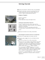
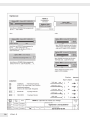
Getting Started
§Remove the interface converter from the packaging.
§Check the interface converter immediately for any
visible damage that may have been incurred as a
result of rough handling during shipment.
Equipment Supplied
–Interface converter
– Power supply
– Connecting cable (only with Option A25)
Setting up the Interface Converter
Choose a suitable location where your interface
converter will not be exposed to drafts, heat radiation,
moisture or vibrations.
Make sure to read these operating instructions
carefully before connecting the interface converter to
power.
!Make sure to observe the safety instructions.
Connecting the Interface Converter to AC Power
§ Connect the angle plug to the power jack (9).
§ Plug the power supply into the wall outlet (mains
supply).
!Make sure to observe the safety instructions.
Make sure that the voltage rating printed on this unit
is identical to your local line voltage. If the voltage
specified on the label or the plug design of the power
supply do not match the rating or standard you use,
please contact your Sartorius office or dealer.
Use only genuine Sartorius equipment. Use of AC
adapters or power supplies from other manufacturers,
even if these units have a registered approval rating
from a national testing laboratory, requires the
consent of an authorized Sartorius service technician.
Sartorius technicians are familiar with the relevant
regulations.
Minebea
Minebea
Minebea

6 YDI05-Z
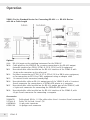
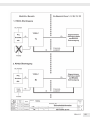
Operation
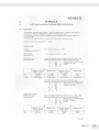
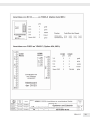
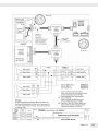
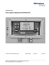
YDI05-Z in the Standard Version for Connecting RS-232 <-> RS-232 Devices
with 20 m Cable Length
Options:
A24: RS-232 input on the weighing instrument for the YDI05-Z
M50 Cable gland on the YDI50-Z for a custom connection to the RS-485 output
(network interface) on CIXS3, FCT01-X, FC-X, FCA-X or IS-X equipment
M51 Non-detachable cable installed on the RS-232 interface of the YDI05-Z with
14-pin male connector on the other end
M52 For direct connection to FCT01-X, FC-X, FCA-X, IS-X or EB-X series equipment,
or for connection to ECX1S or CIXS3 equipment using an adapter cable
M55 12-contact female connector (round plug)
M56 Non-detachable cable on RS-232 output port of the YDI05-Z, with a 9-contact
female connector for connection to a YDP03-0CE printer or a computer
M57 Non-detachable cable installed on the RS-232 output port of the YDI05-Z, with
a 9-pin male connector for connecting the YDP04IS-OCE printer
M58 Non-detachable cable installed on the RS-232 interface of the YDI05-Z, with
25-pin female connector for connecting a computer
Accessories:
YAS04CIS Cable gland, M16 x 1.5 (for cable rather than 12-contact femal connector)
YCC422-X Cable, LiY 6x (2x0, 14mm2 C)Y
69QC0010 12-pin male connector
69Y03166 14-poliger male connector

YDI05-Z 7
7
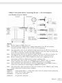
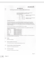
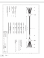
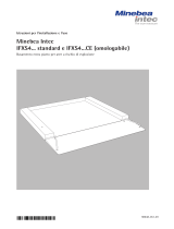
YYDI05-Z with Option A25 for Connecting RS-422 <-> RS-232 Equipment
over Distances of up to 1000 m
Options:
A25 RS-422 input on YDI05-Z for scale
M50 Cable gland on the YDI50-Z for a custom connection to the RS-422 network
interface on CIXS3, FCT01-X, FC-X, FCA-X or IS-X equipment
M53 Non-detachable cable of user-specified length installed on the RS-422 interface of
the YDI05-Z converter, with no connector installed on the other end, for connection
to the RS-422 interface on ECX1S or CIXS3 equipment
M54 Non-detachable cable of user-specified length installed on the RS-422 interface of
the YDI05-Z, with 14-pin round male connector, for direct connection to the
M55 RS-422 interface on FC-X, FCA-X, FCT01-X or IS-X series equipment, or for
connection to ECX1S or CIXS3 devices using an adapter cable
M56 Non-detachable cable on RS-232 output port of the YDI05-Z, with a 9-contact
female connector for connection to a YDP03-0CE printer or a computer
M57 Non-detachable cable installed on the RS-232 output port of the YDI05-Z, with a
9-pin male connector for connecting the YDP04IS-OCE printer
M58 Non-detachable cable installed on the RS-232 interface of the YDI05-Z, with 25-pin
female connector for connecting a computer
Accessories:
YAS04CIS Cable gland, M16 x 1.5 (for cable rather than 12-contact female connector)
YCC422-X Cable, LiY 6x (2x0, 14mm2 C)Y
69QC0010 12-pin male connector
69Y03166 14-pin male connector

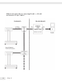
8 YDI05-Z
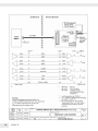
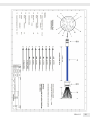
YDI05-Z with option A24 for connecting RS-485 <-> RS-485
over distances of up to 1000 m

YDI05-Z 9
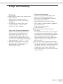
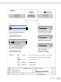
Pflege und Wartung
Sicherheitsüberprüfung
Erscheint ein gefahrloser Betrieb des
Gerätes nicht mehr gewährleistet:
– Wenn das Verbindungskabel sichtbare
Beschädigungen aufweist
– Wenn das Gerät nicht mehr arbeitet
– Nach längerer Lagerung unter ungünsti-
gen Verhältnissen
– Nach schweren Transport-
beanspruchungen
§Die Sicherheits- und Warnhinweise
beachten!
Den Sartorius Kundendienst benachrichti-
gen. Instandsetzungsmaßnahmen dürfen
ausschließlich von Fachkräftenausgeführt
werden, die Zugang zu den nötigen
Instandsetzungs- Unterlagen und Anwei-
sungen haben und an entsprechend
geschult sind.
!Die auf dem Gerät angebrachten Siegel-
marken weisen darauf hin, dass das Gerät
nur durch autorisierte Fachkräfte geöffnet
und gewartet werden darf, damit der
einwandfreie und sichere Betrieb des
Gerätes gewährleistet ist und die Garantie
erhalten bleibt.
Reinigung
!Konzentrierte Säuren und Laugen und
reiner Alkohol
dürfen nicht verwendet werden.
$Flüssigkeit darf nicht in die Waage
eindringen.
$Die Waage mit einem Pinsel oder
einem trockenen, weichen und
fusselfreien Tuch reinigen.
Lager- und Transportbedingungen
$Auf dem Transportweg sind unsere
Geräte soweit wie nötig durch die
Verpackung geschützt. Für eine
Einlagerung der Waage oder einen
eventuell notwendigen Rückversand
alle Teile der Verpackung aufbewahren.
$Lagertemperatur: – 20 °C ... + 75°C
$Zulässige Lagerfeuchte: max. 90%
$Nach den unter Punkt »Sicherheits-
überprüfung« beschriebenen
Anweisungen richten.

10 YDI05-Z
Recycling
Information and Instructions on Disposal
and Repairs
Packaging that is no longer required must
be disposed of at the local waste disposal
facility. The packaging is made of
environmentally friendly materials that can
be used as secondary raw materials. The
equipment, including accessories and
batteries, does not belong in your regular
household waste. The European legislation
requires that electrical and electronic
equipment be collected and disposed of
separately from other communal waste
with the aim of recycling it. In Germany
and many other countries, Sartorius AG
takes care of the return and legally
compliant disposal of its electrical and
electronic equipment on its own.
These products may not be placed with the
household waste or brought to collection
centers run by local public disposal
operations – not even by small commercial
operators.
For disposal in Germany and in the other
member nations of the European Economic
Area (EEA), please contact our Service
technicians on location or our
Service Center in Goettingen, Germany:
Sartorius AG
Service Center
Weender Landstrasse 94-108
37075 Goettingen, Germany
In countries that are not members of the
European Economic Area (EEA) or where
no Sartorius subsidiaries or dealerships are
located, please contact your local
authorities or a commercial disposal
operator.
Prior to disposal and/or scrapping of the
equipment, any batteries should be
removed and disposed of in local
collection boxes.
Sartorius AG will not take back equipment
contaminated with hazardous materials
(ABC contamination) – either for repair or
disposal.
Please refer to the accompanying leaflet/
manual or visit our Internet website
(www.sartorius.com) for comprehensive
information that includes our service
addresses to contact if you plan to send
your equipment in for repairs or proper
disposal.
If you no longer need the packaging after
successful installation of the equipment,
you should return it for recycling.
The packaging is made from
environmentally friendly materials and is a
valuable source of secondary raw
material.
The equipment, including
accessories and batteries,
does not belong in your
regular household waste.
Minebea Intec
Minebea
Minebea Intec
www.minebea-intec.com
Minebea Intec Bovenden GmbH & Co.KG
Leinetal 2
37120 Bovenden
WEEE-Reg.-Nr. DE 58091735

YDI05-Z 11
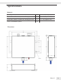
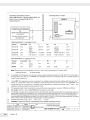
Specifications
Dimensions
YDI05-Z
Humidity class F Non-condensing
Permissible ambient temperature during operation °C -20...+50 (Option A24)
Permissible ambient temperature during operation °C 0...+40 (Option A25)
Power consumption typical VA 8

12 YDI05-Z
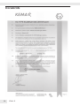
Documents

YDI05-Z 13

14 YDI05-Z

YDI05-Z 15

16 YDI05-Z

YDI05-Z 17

18 YDI05-Z
To verify the availability of the Approved product, please refer to www.approvalguide.com
THIS CERTIFICATE MAY ONLY BE REPRODUCED IN ITS ENTIRETY AND WITHOUT CHANGE
FM Approvals LLC. 1151 Boston-Providence Turnpike, Norwood, MA 02062 USA
F 347 (Mar 16) Page 1 of 3
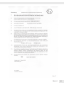
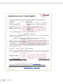
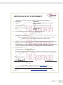
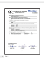
CERTIFICATE OF CONFORMITY
1. HAZARDOUS (CLASSIFIED) LOCATION ELECTRICAL EQUIPMENT PER US REQUIREMENTS
2. Certificate No: FM18US0227X
3. Equipment:
(Type Reference and Name)
Model CAPX..U-……-……, IUX.4-……-…… and IFX.4-……-
….. Weighing Platforms and Model YDI05-Z Interface
Converter
4. Name of Listing Company: Minebea Intec Bovenden GmbH & Co. KG
5. Address of Listing Company: Leinetal 2
37120, Bovenden
Germany
6. The examination and test results are recorded in confidential report number:
3023378 dated 3rd March 2006
7. FM Approvals LLC, certifies that the equipment described has been found to comply with the following Approval
standards and other documents:
FM Class 3600:2018, FM Class 3610:2010, FM Class 3611:2018, FM Class 3810:2018,
ANSI/ISA 60079-0:2009, ANSI/UL 60079-11:2009
8. If the sign ‘X’ is placed after the certificate number, it indicates that the equipment is subject to specific conditions
of use specified in the schedule to this certificate.
9. This certificate relates to the design, examination and testing of the products specified herein. The FM Approvals
surveillance audit program has further determined that the manufacturing processes and quality control
procedures in place are satisfactory to manufacture the product as examined, tested and Approved.
10. Equipment Ratings:
For CAPX..U-...-..., IUX.4-…-..., IFX.4-...-... Weighing Platforms.
Intrinsically Safe circuits or connections for Class I, II, III, Division 1, Groups A, B, C, D, E, F and G T4 at Ta*
when connected per 35739-003-07-A4; Class I Zone 1, AEx ia IIC T4 at Ta* when connected per 35739-003-07-
Certificate issued by:
1 October 2019
J. E. Marquedant
VP, Manager - Electrical Systems
Date

YDI05-Z 19
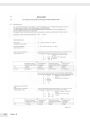
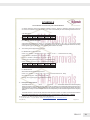
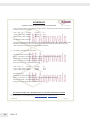
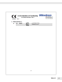
SCHEDULE
US Certificate Of Conformity No: FM18US0227X
THIS CERTIFICATE MAY ONLY BE REPRODUCED IN ITS ENTIRETY AND WITHOUT CHANGE
FM Approvals LLC. 1151 Boston-Providence Turnpike, Norwood, MA 02062 USA
F 347 (Mar 16) Page 2 of 3
A4, Class I, Division 2, Groups A, B, C and D T4 at Max. Ta=50°C; Class II, III, Division 2, Groups E, F and G T4
at Ta=50°C and Class II, Zone 20, IIIC T4 at Ta=* when connected as per control drawings 35739-003-07-A4.
*see table below
Vmax Imax PiCi(cable) Li(cable) Ta
17Vdc 410mA 1.25W 162pF/m 0,6μH/m 60°C
13Vdc 410mA 2.00W 162pF/m 0,6μH/m 40°C
For YDI05-Z.. Interface Converter.
Associated Intrinsically Safe for Class I, II, III, Divisions 1 and 2, Groups A, B, C, D, E, F and G as per control
drawing 65710-800-07-A4; Entity; Class II, [Zone 20], [Ex ia] IIIC as per control drawing 65710-800-07-A4; Entity
Class I, [Zone 0], [Ex ia] IIC as per control drawing 65710-800-07-A4; Entity
11. The marking of the equipment shall include:
For Models CAPX, IUX.4 and IFX.4
Class I, II, III, Division 1, Groups A, B, C, D, E, F and G; T4 Ta = * – 35739-003-07-A4; Entity
Class I, Division 2, Groups A, B, C, D; T4 Ta = +50°C
Class II, III, Division 2, Groups E, F, G; T4 Ta = +50°C
Class II, [Zone 20], [AEx ia] IIIC T4 Ta = * – 35739-003-07-A4;
Class I, Zone 0, AEx ia IIC T4 Ta* – 35739-003-07-A4; Entity
Vmax Imax PiCi(cable) Li(cable) Ta
17Vdc 410mA 1.25W 162pf/m 0,6μH/m 60°C
13Vdc 410mA 2.00W 162pf/m 0,6μH/m 40°C
For Model YDI05-Z
Associated Intrinsically Safe Equipment for:
Class I, II, III, Division 1, Groups A, B, C, D, E, F and G –65710-800-07-A4; Entity
Zone [20], AEx [ib] IIIC – 65710-800-07-A4; Entity
Class [I], Zone [1],AEx [ia] IIC–65710-800-07-A4; Entity
12. Description of Equipment:
The Model CAPX..U-……-……, IUX.4-……-…… and IFX.4-……-….. are stainless steel bench and floor Weighing
Platforms based on strain-gauge load cells. They can be connected to any indicator that fulfils the requirements of
the desired type of protection. The load cells within the weighing platform are powered by the indicator which also
measures the change in resistance within the load cell corresponding to the load that is applied onto the weighing
platform.
The Model YDI05-Z. is an intrinsically safe barrier and interface converter. It is used to connect devices located in

20 YDI05-Z
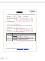
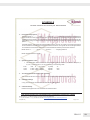
SCHEDULE
US Certificate Of Conformity No: FM18US0227X
THIS CERTIFICATE MAY ONLY BE REPRODUCED IN ITS ENTIRETY AND WITHOUT CHANGE
FM Approvals LLC. 1151 Boston-Providence Turnpike, Norwood, MA 02062 USA
F 347 (Mar 16) Page 3 of 3
the non-hazardous area with devices located in hazardous locations. The signals that are exchanged between
non-hazardous and hazardous areas can be converted between different protocols within YDI05-Z.
Model CAPX..U-……-……, IUX.4-……-…… and IFX.4-……-….. Weighing Platforms
Model YDI05-Z Interface Converter
13. Specific Conditions of Use:
14. Test and Assessment Procedure and Conditions:
This Certificate has been issued in accordance with FM Approvals US Certification Requirements.
15. Schedule Drawings
A copy of the technical documentation has been kept by FM Approvals.
16. Certificate History
Details of the supplements to this certificate are described below:
Date Description
3rd March 2006 Original Issue.
11th November 2018
Supplement 5:
Report Reference: – RR214399 dated 11th November 2018.
Description of the Change: Conversion of certificate to new format, update of several
FM Approval standards, change name on certificate to Minebea Intertec GmbH,
remove Model CS3X, Update FM standards to 2018 revision date.
1st October 2019
Supplement 6:
Report Reference: – RR219894 dated 1st October 2019.
Description of the Change: Correct typing errors.
Pagina se încarcă...
Pagina se încarcă...
Pagina se încarcă...
Pagina se încarcă...
Pagina se încarcă...
Pagina se încarcă...
Pagina se încarcă...
Pagina se încarcă...
Pagina se încarcă...
Pagina se încarcă...
Pagina se încarcă...
Pagina se încarcă...
Pagina se încarcă...
Pagina se încarcă...
Pagina se încarcă...
Pagina se încarcă...
Pagina se încarcă...
Pagina se încarcă...
Pagina se încarcă...
Pagina se încarcă...
Pagina se încarcă...
Pagina se încarcă...
Pagina se încarcă...
Pagina se încarcă...
Pagina se încarcă...
Pagina se încarcă...
Pagina se încarcă...
Pagina se încarcă...
-
 1
1
-
 2
2
-
 3
3
-
 4
4
-
 5
5
-
 6
6
-
 7
7
-
 8
8
-
 9
9
-
 10
10
-
 11
11
-
 12
12
-
 13
13
-
 14
14
-
 15
15
-
 16
16
-
 17
17
-
 18
18
-
 19
19
-
 20
20
-
 21
21
-
 22
22
-
 23
23
-
 24
24
-
 25
25
-
 26
26
-
 27
27
-
 28
28
-
 29
29
-
 30
30
-
 31
31
-
 32
32
-
 33
33
-
 34
34
-
 35
35
-
 36
36
-
 37
37
-
 38
38
-
 39
39
-
 40
40
-
 41
41
-
 42
42
-
 43
43
-
 44
44
-
 45
45
-
 46
46
-
 47
47
-
 48
48


Minebea Intec YDI05-Z Interface Converter Manualul proprietarului
- Tip
- Manualul proprietarului
în alte limbi
Lucrări înrudite
-
 Minebea Intec YDI05-Z Convertitore d‘interfaccia Manualul proprietarului
-
 Minebea Intec YDI05-Z Convertidor de interfaz Manualul proprietarului
-
 Minebea Intec YDI05-Z Convertisseur d’interface Manualul proprietarului
-
 Minebea Intec CAPXS.. Models Stainless Steel Weighing Platforms for Use in Hazardous Areas/Locations Manualul proprietarului
-
 Minebea Intec ISFEG-64-S/CE Weighing Platform Manualul proprietarului
-
 Minebea Intec CAPXS..Wägeplattformen in Edelstahl für explosionsgefährdete Bereiche Manualul proprietarului
-
 Minebea Intec Power supply for digital load cells PR 6024/62S Manualul proprietarului
-
 Minebea Intec IFXS4 Basamento extra piatto per aree a rischio di esplosione Manualul proprietarului
-
 Minebea Intec Economy EC1XS Bilance elettroniche in acciaio inox per le aree a rischio di esplosione Manualul proprietarului
-
 Minebea Intec Economy EC1XS Komplettwaage für explosionsgefährdete Bereiche Manualul proprietarului


