
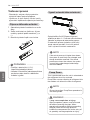
INSTALLATION MANUAL
AIR
CONDITIONER
www.lg.com
[Representative] LG Electronics Inc. EU Representative :
LG Electronics European Shared Service Center B.V.
Krijgsman 1, 1186 DM Amstelveen, The Netherlands
[Manufacturer]
MFL67855550
Rev.00_021319
Copyright © 2019 LG Electronics Inc. All Rights Reserved.
Please read this installation manual completely before installing the product.
Installation work must be performed in accordance with the national wiring
standards by authorized personnel only.
Please retain this installation manual for future reference after reading it thoroughly.
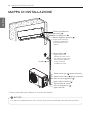
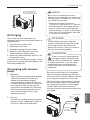
WALL MOUNTED
Original instruction
ENGLISH ITALIANO ESPAÑOL FRANÇAIS DEUTSCH
ΕΛΛΗΝΙΚΆ
ČEŠTINA
NEDERLANDS
POLSKI
LIMBA ROMÂNĂ

ENGLISH
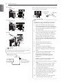
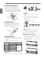
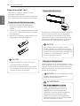
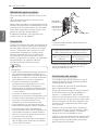
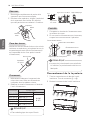
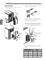
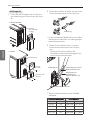
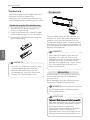
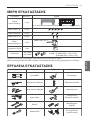
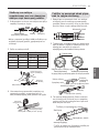
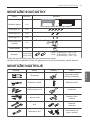
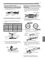
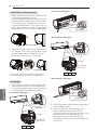
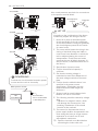
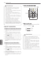
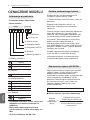
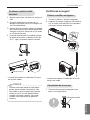
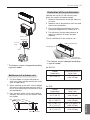
MODEL DESIGNATION
2
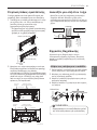
The A-weighted sound pressure emitted by
this product is below 70 dB.
** The noise level can vary depending on the
site.
The figures quoted are emission level and are
not necessarily safe working levels.
Whilst there is a correlation between the
emission and exposure levels, this cannot be
used reliably to determine whether or not
further precautions are required.
Factor that influence the actual level of
exposure of the workforce include the
characteristics of the work room and the other
sources of noise, i.e. the number of
equipment and other adjacent processes and
the length of time for which an operator
exposed to the noise. Also, the permissible
exposure level can vary from country to
country.
This information, however, will enable the
user of the equipment to make a better
evaluation of the hazard and risk.
Airborne Noise Emission
Limiting concentration is the limit of Freon gas
concentration where immediate measures can
be taken without hurting human body when
refrigerant leaks in the air. The limiting
concentration shall be described in the unit of
kg/m
3
(Freon gas weight per unit air volume)
for facilitating calculation
Total amount of replenished
refrigerant in refrigerant facility (kg)
Capacity of smallest room where
indoor unit is installed (m
3
)
Refrigerant
concentration
(kg/m
3
)
=
Limiting concentration: 0.44kg/m
3
(R410A)
Limiting concentration
n Calculate refrigerant concentration
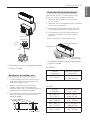
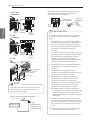
MODEL DESIGNATION
Product information
Model Suffix
- Product Name : Air conditioner
- Model Name :
- Additional Information : serial number is
refer to the barcode on the product.
- Max allowable pressure High side :
4.2 Mpa / Low side : 2.4 Mpa
- Refrigerant : R410A / R32
P M S P07 N SJ
(7) Chassis
(6) Indoor(N)
(5) Serial
(4) Product Look
(3) Capacity (kBTU)
(2) Product
(1) Product Type 1
(1) Product Type 1
D Deluxe
P Standard Plus/Standard
A Artcool
(4) Product Look
R R-Look
S Semi R-Look
E E-Look
B Black Mirror Look
M Multi Compitable
(2) Product
SJ Chassis
SK Chassis
(7) Chassis

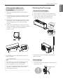
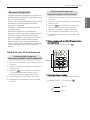
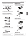
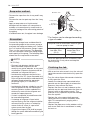
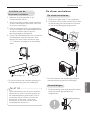
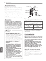
TIPS FOR SAVING ENERGY
ENGLISH
3
• Do not cool excessively indoors. This may be harmful for your health and may consume more
electricity.
• Block sunlight with blinds or curtains while you are operating the air conditioner.
• Keep doors or windows closed tightly while you are operating the air conditioner.
• Adjust the direction of the air flow vertically or horizontally to circulate indoor air.
• Speed up the fan to cool or warm indoor air quickly, in a short period of time.
• Open windows regularly for ventilation as the indoor air quality may deteriorate if the air
conditioner is used for many hours.
• Clean the air filter once every 2 weeks. Dust and impurities collected in the air filter may block the
air flow or weaken the cooling / dehumidifying functions.
For your records
Staple your receipt to this page in case you need it to prove the date of purchase or for warranty
purposes. Write the model number and the serial number here:
Model number :
Serial number :
You can find them on a label on the side of each unit.
Dealer’s name :
Date of purchase :
Here are some tips that will help you minimize the power consumption when you use the air
conditioner. You can use your air conditioner more efficiently by referring to the instructions
below:
TIPS FOR SAVING ENERGY

4
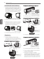
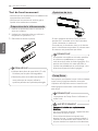
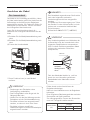
IMPORTANT SAFETY INSTRUCTIONS
ENGLISH
IMPORTANT SAFETY INSTRUCTIONS
The following symbols are displayed on indoor and outdoor units.
READ ALL INSTRUCTIONS BEFORE USING THE APPLIANCE.
Always comply with the following precautions to avoid dangerous
situations and ensure peak performance of your product
WARNING
It can result in serious injury or death when the directions are ignored
CAUTION
It can result in minor injury or product damage when the directions are
ignored
WARNING
• Installation or repairs made by unqualified persons can result in
hazards to you and others.
• Installation MUST conform with local building codes or, in the absence
of local codes, with the Nation Electrical Code NFPA 70/ANSI C1-1003
or current edition and Canadian Electrical Code Part1 CSA C.22.1.
• The information contained in the manual is intended for use by a
qualified service technician familiar with safety procedures and
equipped with the proper tools and test instruments.
• Failure to carefully read and follow all instructions in this manual can
result in equipment malfunction, property damage, personal injury
and/or death.
• Compliance with national gas regulations shall be observed.
Installation
• Always perform grounding.
- Otherwise, it may cause electrical shock.
• Don’t use a power cord, a plug or a loose socket which is damaged.
- Otherwise, it may cause a fire or electrical shock.
!
!
!
Read the precautions in this manual
carefully before operating the unit.
This appliance is filled with
flammable refrigerant (R32)
This symbol indicates that the
Operation Manual should be read
carefully.
This symbol indicates that a service
personnel should be handling this
equipment with reference to the
Installation Manual.

5
ENGLISH
IMPORTANT SAFETY INSTRUCTIONS
• For installation of the product, always contact the service center or a
professional installation agency.
- Otherwise, it may cause a fire, electrical shock, explosion or injury.
• Securely attach the electrical part cover to the indoor unit and the
service panel to the outdoor unit.
- If the electrical part cover of the indoor unit and the service panel of
the outdoor unit are not attached securely, it could result in a fire or
electric shock due to dust, water, etc.
• Always install an air leakage breaker and a dedicated switching board.
- No installation may cause a fire and electrical shock.
• Do not keep or use flammable gases or combustibles near the air
conditioner.
- Otherwise, it may cause a fire or the failure of product.
• Ensure that an installation frame of the outdoor unit is not damaged
due to use for a long time.
- It may cause injury or an accident.
• Do not disassemble or repair the product randomly. - It will cause a
fire or electrical shock.
• Do not install the product at a place that there is concern of falling
down.
- Otherwise, it may result in personal injury.
• Use caution when unpacking and installing. - Sharp edges may cause
injury.
• The appliance shall be stored in a room without continuously
operating ignition sources
(for example: open flames, an operating gas appliance or an operating
electric heater.)
• Two or more people must lift and transport the product. Avoid
personal injury.
• Do not use means to accelerate the defrosting process or to clean,
other than those recommended by the manufacturer.
• Do not pierce or burn refrigerant cycle part.
• Be aware that refrigerants may not contain an odour.
• Keep any required ventilation openings clear of obstruction.
• The appliance shall be stored in a well-ventilated area where the room
size corresponds to the room area as specified for operation.
• Refrigerant tubing shall be protected or enclosed to avoid damage.

ENGLISH
IMPORTANT SAFETY INSTRUCTIONS
6
• Flexible refrigerant connectors (such as connecting lines between the
indoor and outdoor unit) that may be displaced during normal
operations shall be protected against mechanical damage.
• A brazed, welded, or mechanical connection shall be made before
opening the valves to permit refrigerant to flow between the
refrigerating system parts.
• Mechanical connections shall be accessible for maintenance
purposes.
Operation
• Do not share the outlet with other appliances. - It will cause an electric
shock or a fire due to heat generation.
• Do not use the damaged power cord.
- Otherwise, it may cause a fire or electrical shock.
• Do not modify or extend the power cord randomly.
- Otherwise, it may cause a fire or electrical shock.
• Take care so that the power cord may not be pulled during operation.
- Otherwise, it may cause a fire or electrical shock.
• Unplug the unit if strange sounds, smell, or smoke comes from it.
- Otherwise, it may cause electrical shock or a fire.
• Keep the flames away.
- Otherwise, it may cause a fire.
• Take the power plug out if necessary, holding the head of the plug
and do not touch it with wet hands.
- Otherwise, it may cause a fire or electrical shock.
• Do not use the power cord near the heating tools.
- Otherwise, it may cause a fire and electrical shock.
• Do not open the suction inlet of the indoor/outdoor unit during
operation.
- Otherwise, it may electrical shock and failure.
• Do not allow water to run into electrical parts.
- Otherwise, it may cause the failure of machine or electrical shock.
• Hold the plug by the head when taking it out. - It may cause electric
shock and damage.
• Never touch the metal parts of the unit when removing the filter. -
They are sharp and may cause injury.
• Do not step on the indoor/outdoor unit and do not put anything on it. -
It may cause an injury through dropping of the unit or falling down.

IMPORTANT SAFETY INSTRUCTIONS
ENGLISH
7
• Do not place a heavy object on the power cord.
- Otherwise, it may cause a fire or electrical shock.
• When the product is submerged into water, always contact the
service center.
- Otherwise, it may cause a fire or electrical shock.
• Take care so that children may not step on the outdoor unit.
- Otherwise, children may be seriously injured due to falling down.
• Use a vacuum pump or inert (nitrogen) gas when doing leakage test or
air purge. Do not compress air or oxygen, and do not use flammable
gases.
Otherwise, it may cause fire or explosion. - There is the risk of death,
injury, fire or explosion.
• Do not turn on the breaker or power under condition that front panel,
cabinet, top cover, control box cover are removed or opened.
- Otherwise, it may cause fire, electric shock, explosion or death.
• Turn off all devices that cause fire when the refrigerant leaks.,
ventilate the room (example : opening window or using ventilation
unit), and contact with dealer who you purchased the unit.
• The installation of pipe-work shall be kept to a minimum.
• When mechanical connectors are reused indoors, sealing parts shall
be renewed.(for R32)
• When flared joints are reused indoors, the flare part shall be re-
fabricated.(for R32)
CAUTION
Installation
• Install the drain hose to ensure that drain can be securely done. -
Otherwise, it may cause water leakage.
• Install the product so that the noise or hot wind from the outdoor unit
may not cause any damage to the neighbors.
- Otherwise, it may cause dispute with the neighbors.
• Always inspect gas leakage after the installation and repair of product.
- Otherwise, it may cause the failure of product.
• Keep level parallel in installing the product. - Otherwise, it may cause
vibration or water leakage.
• Any person who is involved with working on or breaking into a
!

8
IMPORTANT SAFETY INSTRUCTIONS
ENGLISH
refrigerant circuit should hold a current valid certificate from an
industry-accredited assessment authority, which authorises their
competence to handle refrigerants safely in accordance with an
industry recognised assessment specification. (for R32)
• Wear adequate personal protection equipment (PPE) when installing,
maintaining or servicing the product.
Operation
• Avoid excessive cooling and perform ventilation sometimes.
- Otherwise, it may do harm to your health.
• Use a soft cloth to clean. Do not use wax, thinner, or a strong
detergent. - The appearance of the air conditioner may deteriorate,
change color, or develop surface flaws.
• Do not use an appliance for special purposes such as preserving
animals vegetables, precision machine, or art articles.
- Otherwise, it may damage your properties.
• Do not place obstacles around the flow inlet or outlet.
- Otherwise, it may cause the failure of appliance or an accident.
• The appliance shall be stored so as to prevent mechanical damage
from occurring.
• Servicing shall only be performed as recommended by the equipment
manufacturer. Maintenance and repair requiring the assistance of
other skilled personnel shall be carried out under the supervision of
the person competent in the use of flammable refrigerants. (for R32)
• Dismantling the unit, treatment of the refrigerant oil and eventual
parts should be done in accordance with local and national standards.
• Periodic ( more than once/year ) cleaning of the dust or salt particles
stuck on the heat exchanger by using water.
• Means for disconnection must be incorporated in the fixed wiring in
accordance with the wiring rules

ENGLISH
9
2 MODEL DESIGNATION
3 TIPS FOR SAVING ENERGY
4 IMPORTANT SAFETY INSTRUCTIONS
10 INTRODUCTION
10 Symbols used in this Manual
10 Features
11 INSTALLATION PARTS
11 INSTALLATION TOOLS
12 INSTALLATION MAP
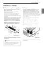
13 INSTALLATION
13 Select the best Location
13 Outdoor unit
15 Fixing Installation Plate
15 Drill a Hole in the Wall
15 Flaring Work
16 Connecting the Piping
21 Connecting the Cables
23 Checking the Drainage
24 Installing drain piping of the outdoor unit
24 Forming the Piping
25 Air P
urging
25 Air purging with vacuum pump
28 Tes t R unning
29 Heating Only Mode
30 SMART DIAGNOSIS
31Installation guide at theseaside
32Piping Length and Elevation
33 Manual the decor, air filter Assembly & Disassembly
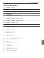
TABLE OF CONTENTS
TABLE OF CONTENTS

10
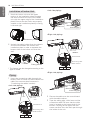
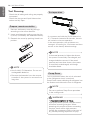
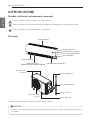
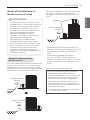
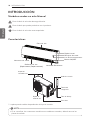
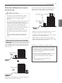
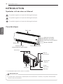
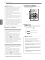
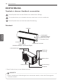
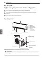
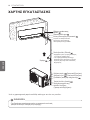
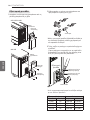
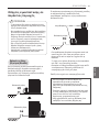
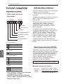
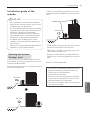
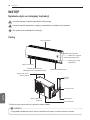
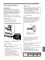
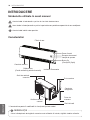
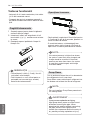
INTRODUCTION
ENGLISH
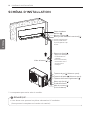
!
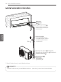
Air Intake Vents
Connecting
Wires
Piping
Air Outlet Vents
Base Plate
Drain Hose
* The feature can be changed according to type of model.
NOTE
!
• When mechanical connectors are reused indoors, sealing parts shall be renewed.
Front grille
Air filter
On/Off button
Signal receiver
Display
Plasmaster Ionizer
Air deflector
(Vertical louver & Horizontal vane)
Air outlet
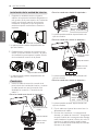
Symbols used in this Manual
This symbol alerts you to the risk of electric shock.
This symbol alerts you to hazards that may cause harm to the air conditioner.
This symbol indicates special notes.
Features
!
INTRODUCTION

INSTALLATION PARTS
ENGLISH
11
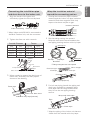
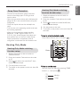
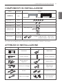
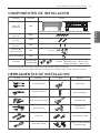
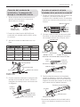
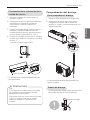
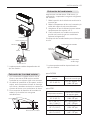
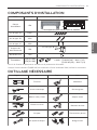
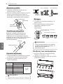
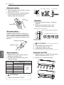
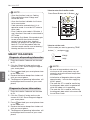
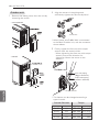
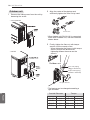
INSTALLATION TOOLS
Name
Quantity Shape
Installation plate
1 EA
Cloth tape
Connector
1 EA
Type "A" screw
5 EA
Type "B" screw
2 EA
Type "C" screw
2 EA
Remote control
holder
1 EA
1 EA (5.0 kW)
2 EA (6.6 kW)
The feature can be changed according to type of model.
Type “B” screw
5.0 kW : ڸØ9.52 (3/8) ơ Ø12.7 (1/2)
6.6 kW : ڸØ9.52 (3/8) ơ Ø12.7 (1/2)
ڹØ15.88 (5/8) ơ Ø12.7 (1/2)
Screws for fixing panels are attached to decoration panel.
When Indoor unit (5.0/6.6 kW) is connected to the Multi Outdoor unit, use the connector.
Figure FigureName
Screw driver
Electric drill
Measuring tape, Knife
Hole core drill
Spanner
Torque wrench
Multi-meter
Hexagonal wrench
Ammeter
Gas-leak detector
Thermometer,
Level
Flaring tool set
Name
INSTALLATION PARTS

12
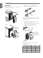
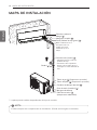
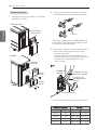
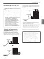
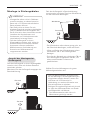
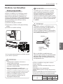
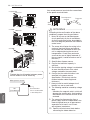
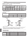
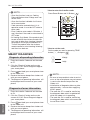
INSTALLATION MAP
ENGLISH
Connecting cable
(Optional Parts)
Vinyl tape (Wide)
• Apply after carrying out a
drainage test.
• To carry out the drainage
test, remove the air filters
and pour water into the heat
exchanger.
Saddle
Gas side piping (Optional Parts)
Liquid side piping (Optional Parts)
Additional drain pipe
Vinyl tape (Narrow)
Drain hose
Installation plate
Sleeve
Bushing-Sleeve
Putty(Gum Type Sealant)
Bend the pipe as closely
on the wall as possible,
but be careful that it
doesn't break.
NOTE
!
• You should purchase the installation parts. (lt can be changed according to market)
* The feature can be changed according a type of model.
* Work to the vinyl tape should up from below.
INSTALLATION MAP

INSTALLATION
ENGLISH
13
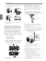
* The feature can be changed according to
type of model.
* The feature can be changed according to
type of model.
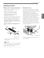
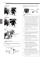
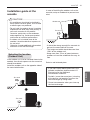
More Than
200
More Than
100
More Than
100
(Unit : mm)
More Than
2 300
More than
300
More than
300
Sunroof
Fence or
obstacles
More than
700
More than
600
(Unit : mm)
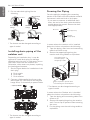
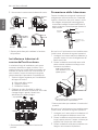
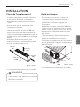
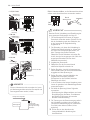
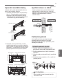
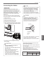
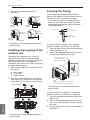
NOTE
!
The gap between the indoor unit and
ceiling is needed more than 200 mm for
disassemble the air filter.
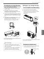
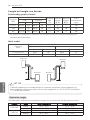
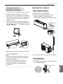
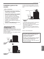
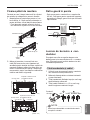
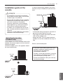
Outdoor unit
- If an awning is built over the unit to prevent
direct sunlight or rain exposure, make sure
that heat radiation from the condenser is not
restricted.
- Ensure that the space around the back and
sides is more than 300 mm. The space in
front of the unit should be more than 700 mm
of space.
- Do not place animals and plants in the path of
the warm air.
- Take the weight of the air conditioner into
account and select a place where noise and
vibration are minimum.
- Select a place where the warm air and noise
from the air conditioner do not disturb
neighbors.
Select the best Location
- There should not be any heat or steam near
the unit.
- Select a place where there are no obstacles
around of the unit.
- Make sure that condensation drainage can
be conveniently routed away.
- Do not install near a doorway.
- Ensure that the interval between a wall and
the left (or right) of the unit is more than
100mm. The unit should be installed as high
as possible on the wall, allowing a minimum
of 200 mm from ceiling.
- Use a metal detector to locate studs to
prevent unnecessary damage to the wall.
INSTALLATION

14
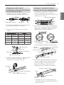
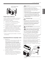
INSTALLATION
ENGLISH
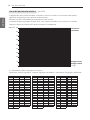
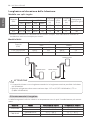
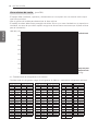
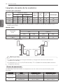
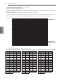
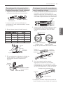
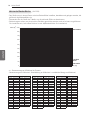
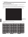
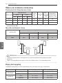
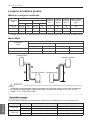
- The appliance shall be installed, operated and stored in a room with a floor area larger than the
minimum area.
- Use the graph of table to determine the minimum area.
- m : Total refrigerant amount in the system
- Total refrigerant amount : factory refrigerant charge + additional refrigerant amount
- Amin : minimum area for installation
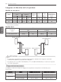
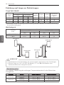
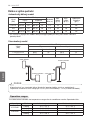
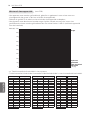
Minimum floor area
0
100
200
300
400
500
600
Amin (m
2
)
m (kg)
0 1.224 2 3 4 5 6 7 8
Floor standing
Wall mounted
Ceiling mounted
Floor location
m (kg) Amin (m
2
)
< 1.224
-
1.224
12.9
1.4 16.82
1.6 21.97
1.8 27.80
2 34.32
2.2 41.53
2.4 49.42
2.6 58.00
2.8 67.27
3 77.22
3.2 87.86
3.4 99.19
3.6 111.20
3.8 123.90
4 137.29
4.2 151.36
4.4 166.12
Floor location
m (kg) Amin (m
2
)
4.6 181.56
4.8 197.70
5 214.51
5.2 232.02
5.4 250.21
5.6 269.09
5.8 288.65
6 308.90
6.2 329.84
6.4 351.46
6.6 373.77
6.8 396.76
7 420.45
7.2 444.81
7.4 469.87
7.6 495.61
7.8 522.04
Wall mounted
m (kg) Amin (m
2
)
< 1.224
-
1.224
1.43
1.4 1.87
1.6 2.44
1.8 3.09
2 3.81
2.2 4.61
2.4 5.49
2.6 6.44
2.8 7.47
3 8.58
3.2 9.76
3.4 11.02
3.6 12.36
3.8 13.77
4 15.25
4.2 16.82
4.4 18.46
Wall mounted
m (kg) Amin (m
2
)
4.6 20.17
4.8 21.97
5 23.83
5.2 25.78
5.4 27.80
5.6 29.90
5.8 32.07
6 34.32
6.2 36.65
6.4 39.05
6.6 41.53
6.8 44.08
7 46.72
7.2 49.42
7.4 52.21
7.6 55.07
7.8 58.00
Ceiling Mounted
m (kg) Amin (m
2
)
< 1.224
-
1.224
0.956
1.4 1.25
1.6 1.63
1.8 2.07
2 2.55
2.2 3.09
2.4 3.68
2.6 4.31
2.8 5.00
3 5.74
3.2 6.54
3.4 7.38
3.6 8.27
3.8 9.22
4 10.21
4.2 11.26
4.4 12.36
Ceiling Mounted
m (kg) Amin (m
2
)
4.6 13.50
4.8 14.70
5 15.96
5.2 17.26
5.4 18.61
5.6 20.01
5.8 21.47
6 22.98
6.2 24.53
6.4 26.14
6.6 27.80
6.8 29.51
7 31.27
7.2 33.09
7.4 34.95
7.6 36.86
7.8 38.83
(for R32)

INSTALLATION
ENGLISH
15
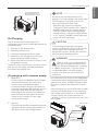
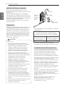
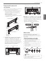
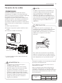
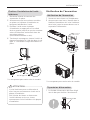
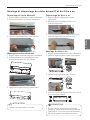
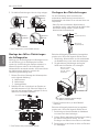
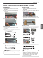
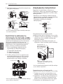
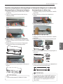
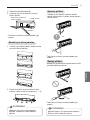
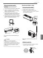
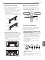
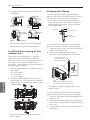
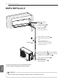
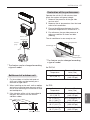
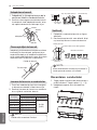
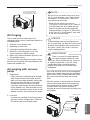
Fixing Installation Plate
The wall you select should be strong and solid
enough to prevent vibration
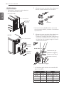
1 Mount the installation plate on the wall
with type "A" screws. If mounting the unit
on a concrete wall, use anchor bolts.
- Mount the installation plate horizontally
by aligning the centerline using Horizontal
meter.
2 Measure the wall and mark the centerline.
It is also important to use caution
concerning the location of the installation
plate. Routing of the wiring to power
outlets is through the walls typically.
Drilling the hole through the wall for piping
connections must be done safely.
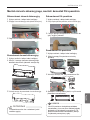
Drill a Hole in the Wall
- Drill the piping hole with a ø65mm hole core
drill. Drill the piping hole at either the right or
the left with the hole slightly slanted to the
outdoor side.
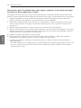
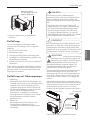
Flaring Work
Main cause for gas leakage is due to defect of
flaring work. Carry out correct flaring work in
the following procedure.
Cut the pipes and the cable
1 Use the piping kit accessory or the pipes
purchased locally.
2 Measure the distance between the indoor
and the outdoor unit.
3 Cut the pipes a little longer than measured
distance.
4 Cut the cable 1.5 m longer than the pipe
length.
5-7 mm
(3/16"~5/16")
Indoor
WALL
Outdoor
Copper
pipe
90°
Slanted Uneven Rough
Installation Plate
Installation Plate
Chassis
Hook
Chassis
Hook
Type "A" Screws
Type "A" Screws
C Type: 494 C Type: 504
Place a level on raised tab
Unit Outline
83
C Type: 134
Measuring Tape
Ø65
83
Measuring Tape
Hanger
Ø65
C Type: 150
(Unit : mm)
(Unit : mm)
194152
Ø65
Right rear piping
Right rear piping
Left rear piping
Left rear piping
Ø65
C Type : 134C Type : 98
C Type
C Type : 418 C Type : 418
Place a level on raised tab
Unit Outline
Installation Plate
NOTE
!
• Use the deoxidised copper as piping
materials to install.

16
INSTALLATION
ENGLISH
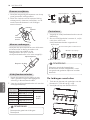
Inclined
Inside is shiny without scratches
Smooth all round
Even length
all round
Surface
damaged
Cracked Uneven
thickness
= Improper flaring =
Burrs removal
1 Completely remove all burrs from the cut
cross section of pipe/tube.
2 While removing burrs put the end of the
copper tube/pipe in a downward direction
while removing burrs location is also
changed in order to avoid dropping burrs
into the tubing.
Putting nut on
- Remove flare nuts attached to indoor and
outdoor unit, then put them on pipe/tube
having completed burr removal.
(not possible to put them on after finishing
flare work)
Flaring work
1 Firmly hold copper pipe in a bar with the
dimension shown in below table.
2 Carry out flaring work with the flaring tool.
Check
1 Compare the flared work with the figure
by.
2 If a flared section is defective, cut it off
and do flaring work again.
Connecting the Piping
1 Pull the cover at the bottom of the indoor
unit. Pull the cover ①→②.
2 Remove the cover from the indoor unit.
Pipe
Reamer
Point down
Flare nut
Copper tube
NOTE
!
• Temper grade of pipe: Annealed.
NOTE
!
• When flared joints are reused indoors,
the flare part shall be re-fabricated.
<Clutch type>
Bar
"A"
<Wing nut type>
Copper
pipe
Pipe diameter
Inch (mm)
A Inch (mm)
Thickness
Inch (mm)
Wing nut type
Clutch type
Ø1/4 (Ø6.35)
0.04~0.05 (1.1~1.3)
0~0.02
(0~0.5)
0.03 (0.7)
Ø3/8 (Ø9.52)
0.06~0.07 (1.5~1.7)
0.03 (0.8)
Ø1/2 (Ø12.7)
0.06~0.07 (1.6~1.8)
0.03 (0.8)
Ø5/8 (Ø15.88)
0.06~0.07 (1.6~1.8)
0.04 (1.0)
Ø3/4 (Ø19.05)
0.07~0.08 (1.9~2.1)
0.04 (1.0)

INSTALLATION
ENGLISH
17
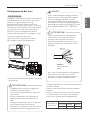
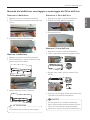
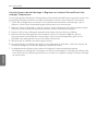
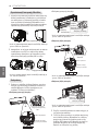
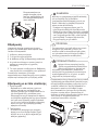
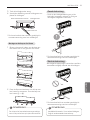
3 Pull back the tubing holder.
4 Remove pipe port cover and positioning
the tubing
* The feature can be changed according to
type of model.
1 Insert 4 hooks of the chassis cover into
gap of the chassis certainly.
2 Push the 6 point hook to assemble chassis
cover. Push the chassis cover ①→②.
Assembly of chassis cover
Right
Indoor unit back side view
Tubing holder
Left
Backwards
- Press on the tubing cover and unfold the
tubing to downward slowly. And then bend
to the left side slowly.
* The feature can be changed according to
type of model.
- Following bending case from right to left
directly may cause damage to the tubing.
* The feature can be changed according to
type of model.
Good case
Bad case
NOTE
!
To protect the chassis cover bended,
assembly chassis cover correctly.
NOTE
!
Installation Information. For right piping.
Follow the instruction above.

18
INSTALLATION
ENGLISH
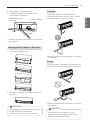
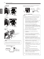
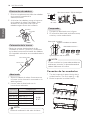
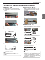
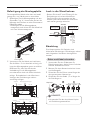
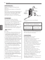
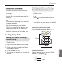
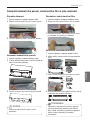
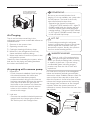
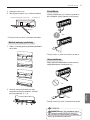
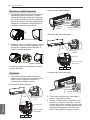
Installation of Indoor Unit
1 Hook the indoor unit onto the upper
portion of the installation plate.( engage
the three hooks at the top of the indoor
unit with the upper edge of the installation
plate) Ensure that the hooks are properly
seated on the installation plate by moving
it left and right
2 Unlock the tubing holder from the chassis
and mount between the chassis and
installation plate in order to separate the
bottom side of the indoor unit from the
wall.
*
The feature can be changed according to the
type of model.
Piping
1 Insert the connecting cable through the
bottom side of indoor unit and connect the
cable (You can see detail contents in
'Connecting the cables' section)
<Left side piping>
View
Terminal block
Connecting cable
Cable retainer
Slide up the metal
plate cover
Installation plate
Tubing Holder
1(L) 2(N) 3(C)
<Left side piping>
<Right side piping>
<Right side piping>
2 Secure the cable onto the control board
with the cable retainer.
3 Tape the tubing pipe, drain hose and the
connection cable. Be sure that the drain
hose is located at the lowest side of the
bundle. Locating at the upper side can
cause overflow from the drain pan through
the inside of the unit.
View
Terminal block
Connecting cable
Cable retainer
Slide up the metal
plate cover
Drain hose
Connecting pipe
Connecting
cable
Tape
Drain hose
Connecting pipe
Connecting
cable
Tape
Drain hose
1(L) 2(N) 3(C)

INSTALLATION
ENGLISH
19
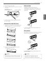
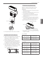
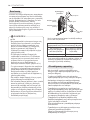
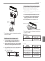
Insulation material
Connecting the installation pipe
and drain hose to the indoor unit.
1 Align the center of the pipes and
sufficiently tighten the flare nut by hand
* When Indoor unit (6.6 kW) is connected to
the Multi Outdoor unit, use the connector.
2 Tighten the flare nut with a wrench
3 When needed to extend the drain hose of
indoor unit, assembly the drain pipe as
shown on the drawing
Wrap the insulation material
around the connecting portion.
1 Overlap the connection pipe insulation
material and the indoor unit pipe insulation
material. Bind them together with vinyl
tape so that there may be no gap.
2 Set the tubing cutting line upward.
Wrap the area which accommodates the
rear piping housing section with vinyl tape.
3 For left rear piping, bundle the piping and
drain hose together by wrapping them
cloth tape over the range within which
they fit into the rear piping housing
section.
* Wrap the piping of the indoor unit that are
visible from the outside with vinyl tape.
Torque wrench
Indoor unit tubing
Spanner
(fixed)
Connection
pipe
Flare nut
Vinyl tape(narrow)
Adhesive
Drain pipe
Indoor unit drain hose
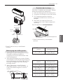
mm inch kgf
.
cm N
.
m
Ø6.35 1/4 180~250 17.6~24.5
Ø9.52 3/8 340~420 33.3~41.2
Ø12.7 1/2 550~660 53.9~64.7
Ø15.88 5/8 630~820 61.7~80.4
Outside Diameter Torque
Indoor unit tubing Flare nut Pipes
Vinyl tape(narrow)
Connection pipe
Connecting cable
Cloth tape
Wrap with cloth tape
Indoor unit pipe
Pipe
Wrap with cloth tape
Drain hose
Pipe
Cloth tape
Gas Pipe
Liquid Pipe
Cutting Line
Cutting Line
Good Case Bad Case
* Tubing cutting line have to be upward.

20
INSTALLATION
ENGLISH
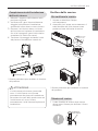
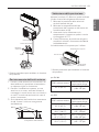
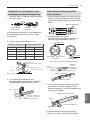
Outdoor unit
1 Remove the tubing cover from the unit by
loosening the screw.
• 6.6 kW
• 2.5/3.5/5.0 kW
2 Align the center of the pipings and
sufficiently tighten the flare nut by hand.
* When Indoor unit(5.0/6.6 kW) is connected
to the Multi Outdoor unit, use the connector
shown above.
3 Finally, tighten the flare nut with torque
wrench until the wrench clicks.
- When tightening the flare nut with torque
wrench, ensure the direction for
tightening follows the arrow on the
wrench.
* The feature can be changed according a
type of model.
Connector
Gas side piping
(Bigger diameter)
Liquid side piping
(Smaller diameter)
Torque wrench
Outdoor unit
mm inch kgf
.
cm N
.
m
Ø6.35 1/4 180~250 17.6~24.5
Ø9.52 3/8 340~420 33.3~41.2
Ø12.7 1/2 550~660 53.9~64.7
Ø15.88 5/8 630~820 61.7~80.4
Outside Diameter Torque
Pagina se încarcă...
Pagina se încarcă...
Pagina se încarcă...
Pagina se încarcă...
Pagina se încarcă...
Pagina se încarcă...
Pagina se încarcă...
Pagina se încarcă...
Pagina se încarcă...
Pagina se încarcă...
Pagina se încarcă...
Pagina se încarcă...
Pagina se încarcă...
Pagina se încarcă...
Pagina se încarcă...
Pagina se încarcă...
Pagina se încarcă...
Pagina se încarcă...
Pagina se încarcă...
Pagina se încarcă...
Pagina se încarcă...
Pagina se încarcă...
Pagina se încarcă...
Pagina se încarcă...
Pagina se încarcă...
Pagina se încarcă...
Pagina se încarcă...
Pagina se încarcă...
Pagina se încarcă...
Pagina se încarcă...
Pagina se încarcă...
Pagina se încarcă...
Pagina se încarcă...
Pagina se încarcă...
Pagina se încarcă...
Pagina se încarcă...
Pagina se încarcă...
Pagina se încarcă...
Pagina se încarcă...
Pagina se încarcă...
Pagina se încarcă...
Pagina se încarcă...
Pagina se încarcă...
Pagina se încarcă...
Pagina se încarcă...
Pagina se încarcă...
Pagina se încarcă...
Pagina se încarcă...
Pagina se încarcă...
Pagina se încarcă...
Pagina se încarcă...
Pagina se încarcă...
Pagina se încarcă...
Pagina se încarcă...
Pagina se încarcă...
Pagina se încarcă...
Pagina se încarcă...
Pagina se încarcă...
Pagina se încarcă...
Pagina se încarcă...
Pagina se încarcă...
Pagina se încarcă...
Pagina se încarcă...
Pagina se încarcă...
Pagina se încarcă...
Pagina se încarcă...
Pagina se încarcă...
Pagina se încarcă...
Pagina se încarcă...
Pagina se încarcă...
Pagina se încarcă...
Pagina se încarcă...
Pagina se încarcă...
Pagina se încarcă...
Pagina se încarcă...
Pagina se încarcă...
Pagina se încarcă...
Pagina se încarcă...
Pagina se încarcă...
Pagina se încarcă...
Pagina se încarcă...
Pagina se încarcă...
Pagina se încarcă...
Pagina se încarcă...
Pagina se încarcă...
Pagina se încarcă...
Pagina se încarcă...
Pagina se încarcă...
Pagina se încarcă...
Pagina se încarcă...
Pagina se încarcă...
Pagina se încarcă...
Pagina se încarcă...
Pagina se încarcă...
Pagina se încarcă...
Pagina se încarcă...
Pagina se încarcă...
Pagina se încarcă...
Pagina se încarcă...
Pagina se încarcă...
Pagina se încarcă...
Pagina se încarcă...
Pagina se încarcă...
Pagina se încarcă...
Pagina se încarcă...
Pagina se încarcă...
Pagina se încarcă...
Pagina se încarcă...
Pagina se încarcă...
Pagina se încarcă...
Pagina se încarcă...
Pagina se încarcă...
Pagina se încarcă...
Pagina se încarcă...
Pagina se încarcă...
Pagina se încarcă...
Pagina se încarcă...
Pagina se încarcă...
Pagina se încarcă...
Pagina se încarcă...
Pagina se încarcă...
Pagina se încarcă...
Pagina se încarcă...
Pagina se încarcă...
Pagina se încarcă...
Pagina se încarcă...
Pagina se încarcă...
Pagina se încarcă...
Pagina se încarcă...
Pagina se încarcă...
Pagina se încarcă...
Pagina se încarcă...
Pagina se încarcă...
Pagina se încarcă...
Pagina se încarcă...
Pagina se încarcă...
Pagina se încarcă...
Pagina se încarcă...
Pagina se încarcă...
Pagina se încarcă...
Pagina se încarcă...
Pagina se încarcă...
Pagina se încarcă...
Pagina se încarcă...
Pagina se încarcă...
Pagina se încarcă...
Pagina se încarcă...
Pagina se încarcă...
Pagina se încarcă...
Pagina se încarcă...
Pagina se încarcă...
Pagina se încarcă...
Pagina se încarcă...
Pagina se încarcă...
Pagina se încarcă...
Pagina se încarcă...
Pagina se încarcă...
Pagina se încarcă...
Pagina se încarcă...
Pagina se încarcă...
Pagina se încarcă...
Pagina se încarcă...
Pagina se încarcă...
Pagina se încarcă...
Pagina se încarcă...
Pagina se încarcă...
Pagina se încarcă...
Pagina se încarcă...
Pagina se încarcă...
Pagina se încarcă...
Pagina se încarcă...
Pagina se încarcă...
Pagina se încarcă...
Pagina se încarcă...
Pagina se încarcă...
Pagina se încarcă...
Pagina se încarcă...
Pagina se încarcă...
Pagina se încarcă...
Pagina se încarcă...
Pagina se încarcă...
Pagina se încarcă...
Pagina se încarcă...
Pagina se încarcă...
Pagina se încarcă...
Pagina se încarcă...
Pagina se încarcă...
Pagina se încarcă...
Pagina se încarcă...
Pagina se încarcă...
Pagina se încarcă...
Pagina se încarcă...
Pagina se încarcă...
Pagina se încarcă...
Pagina se încarcă...
Pagina se încarcă...
Pagina se încarcă...
Pagina se încarcă...
Pagina se încarcă...
Pagina se încarcă...
Pagina se încarcă...
Pagina se încarcă...
Pagina se încarcă...
Pagina se încarcă...
Pagina se încarcă...
Pagina se încarcă...
Pagina se încarcă...
Pagina se încarcă...
Pagina se încarcă...
Pagina se încarcă...
Pagina se încarcă...
Pagina se încarcă...
Pagina se încarcă...
Pagina se încarcă...
Pagina se încarcă...
Pagina se încarcă...
Pagina se încarcă...
Pagina se încarcă...
Pagina se încarcă...
Pagina se încarcă...
Pagina se încarcă...
Pagina se încarcă...
Pagina se încarcă...
Pagina se încarcă...
Pagina se încarcă...
Pagina se încarcă...
Pagina se încarcă...
Pagina se încarcă...
Pagina se încarcă...
Pagina se încarcă...
Pagina se încarcă...
Pagina se încarcă...
Pagina se încarcă...
Pagina se încarcă...
Pagina se încarcă...
Pagina se încarcă...
Pagina se încarcă...
Pagina se încarcă...
Pagina se încarcă...
Pagina se încarcă...
Pagina se încarcă...
Pagina se încarcă...
Pagina se încarcă...
Pagina se încarcă...
Pagina se încarcă...
Pagina se încarcă...
Pagina se încarcă...
Pagina se încarcă...
Pagina se încarcă...
Pagina se încarcă...
Pagina se încarcă...
Pagina se încarcă...
Pagina se încarcă...
Pagina se încarcă...
Pagina se încarcă...
Pagina se încarcă...
Pagina se încarcă...
Pagina se încarcă...
Pagina se încarcă...
Pagina se încarcă...
Pagina se încarcă...
Pagina se încarcă...
Pagina se încarcă...
Pagina se încarcă...
Pagina se încarcă...
Pagina se încarcă...
Pagina se încarcă...
Pagina se încarcă...
Pagina se încarcă...
Pagina se încarcă...
Pagina se încarcă...
Pagina se încarcă...
Pagina se încarcă...
Pagina se încarcă...
Pagina se încarcă...
Pagina se încarcă...
Pagina se încarcă...
Pagina se încarcă...
Pagina se încarcă...
Pagina se încarcă...
Pagina se încarcă...
Pagina se încarcă...
Pagina se încarcă...
Pagina se încarcă...
Pagina se încarcă...
Pagina se încarcă...
Pagina se încarcă...
Pagina se încarcă...
Pagina se încarcă...
Pagina se încarcă...
Pagina se încarcă...
Pagina se încarcă...
Pagina se încarcă...
Pagina se încarcă...
Pagina se încarcă...
Pagina se încarcă...
Pagina se încarcă...
Pagina se încarcă...
Pagina se încarcă...
Pagina se încarcă...
Pagina se încarcă...
Pagina se încarcă...
Pagina se încarcă...
Pagina se încarcă...
Pagina se încarcă...
Pagina se încarcă...
Pagina se încarcă...
Pagina se încarcă...
Pagina se încarcă...
Pagina se încarcă...
Pagina se încarcă...
Pagina se încarcă...
Pagina se încarcă...
Pagina se încarcă...
Pagina se încarcă...
Pagina se încarcă...
Pagina se încarcă...
Pagina se încarcă...
Pagina se încarcă...
Pagina se încarcă...
Pagina se încarcă...
-
 1
1
-
 2
2
-
 3
3
-
 4
4
-
 5
5
-
 6
6
-
 7
7
-
 8
8
-
 9
9
-
 10
10
-
 11
11
-
 12
12
-
 13
13
-
 14
14
-
 15
15
-
 16
16
-
 17
17
-
 18
18
-
 19
19
-
 20
20
-
 21
21
-
 22
22
-
 23
23
-
 24
24
-
 25
25
-
 26
26
-
 27
27
-
 28
28
-
 29
29
-
 30
30
-
 31
31
-
 32
32
-
 33
33
-
 34
34
-
 35
35
-
 36
36
-
 37
37
-
 38
38
-
 39
39
-
 40
40
-
 41
41
-
 42
42
-
 43
43
-
 44
44
-
 45
45
-
 46
46
-
 47
47
-
 48
48
-
 49
49
-
 50
50
-
 51
51
-
 52
52
-
 53
53
-
 54
54
-
 55
55
-
 56
56
-
 57
57
-
 58
58
-
 59
59
-
 60
60
-
 61
61
-
 62
62
-
 63
63
-
 64
64
-
 65
65
-
 66
66
-
 67
67
-
 68
68
-
 69
69
-
 70
70
-
 71
71
-
 72
72
-
 73
73
-
 74
74
-
 75
75
-
 76
76
-
 77
77
-
 78
78
-
 79
79
-
 80
80
-
 81
81
-
 82
82
-
 83
83
-
 84
84
-
 85
85
-
 86
86
-
 87
87
-
 88
88
-
 89
89
-
 90
90
-
 91
91
-
 92
92
-
 93
93
-
 94
94
-
 95
95
-
 96
96
-
 97
97
-
 98
98
-
 99
99
-
 100
100
-
 101
101
-
 102
102
-
 103
103
-
 104
104
-
 105
105
-
 106
106
-
 107
107
-
 108
108
-
 109
109
-
 110
110
-
 111
111
-
 112
112
-
 113
113
-
 114
114
-
 115
115
-
 116
116
-
 117
117
-
 118
118
-
 119
119
-
 120
120
-
 121
121
-
 122
122
-
 123
123
-
 124
124
-
 125
125
-
 126
126
-
 127
127
-
 128
128
-
 129
129
-
 130
130
-
 131
131
-
 132
132
-
 133
133
-
 134
134
-
 135
135
-
 136
136
-
 137
137
-
 138
138
-
 139
139
-
 140
140
-
 141
141
-
 142
142
-
 143
143
-
 144
144
-
 145
145
-
 146
146
-
 147
147
-
 148
148
-
 149
149
-
 150
150
-
 151
151
-
 152
152
-
 153
153
-
 154
154
-
 155
155
-
 156
156
-
 157
157
-
 158
158
-
 159
159
-
 160
160
-
 161
161
-
 162
162
-
 163
163
-
 164
164
-
 165
165
-
 166
166
-
 167
167
-
 168
168
-
 169
169
-
 170
170
-
 171
171
-
 172
172
-
 173
173
-
 174
174
-
 175
175
-
 176
176
-
 177
177
-
 178
178
-
 179
179
-
 180
180
-
 181
181
-
 182
182
-
 183
183
-
 184
184
-
 185
185
-
 186
186
-
 187
187
-
 188
188
-
 189
189
-
 190
190
-
 191
191
-
 192
192
-
 193
193
-
 194
194
-
 195
195
-
 196
196
-
 197
197
-
 198
198
-
 199
199
-
 200
200
-
 201
201
-
 202
202
-
 203
203
-
 204
204
-
 205
205
-
 206
206
-
 207
207
-
 208
208
-
 209
209
-
 210
210
-
 211
211
-
 212
212
-
 213
213
-
 214
214
-
 215
215
-
 216
216
-
 217
217
-
 218
218
-
 219
219
-
 220
220
-
 221
221
-
 222
222
-
 223
223
-
 224
224
-
 225
225
-
 226
226
-
 227
227
-
 228
228
-
 229
229
-
 230
230
-
 231
231
-
 232
232
-
 233
233
-
 234
234
-
 235
235
-
 236
236
-
 237
237
-
 238
238
-
 239
239
-
 240
240
-
 241
241
-
 242
242
-
 243
243
-
 244
244
-
 245
245
-
 246
246
-
 247
247
-
 248
248
-
 249
249
-
 250
250
-
 251
251
-
 252
252
-
 253
253
-
 254
254
-
 255
255
-
 256
256
-
 257
257
-
 258
258
-
 259
259
-
 260
260
-
 261
261
-
 262
262
-
 263
263
-
 264
264
-
 265
265
-
 266
266
-
 267
267
-
 268
268
-
 269
269
-
 270
270
-
 271
271
-
 272
272
-
 273
273
-
 274
274
-
 275
275
-
 276
276
-
 277
277
-
 278
278
-
 279
279
-
 280
280
-
 281
281
-
 282
282
-
 283
283
-
 284
284
-
 285
285
-
 286
286
-
 287
287
-
 288
288
-
 289
289
-
 290
290
-
 291
291
-
 292
292
-
 293
293
-
 294
294
-
 295
295
-
 296
296
-
 297
297
-
 298
298
-
 299
299
-
 300
300
-
 301
301
-
 302
302
-
 303
303
-
 304
304
-
 305
305
-
 306
306
-
 307
307
-
 308
308
-
 309
309
-
 310
310
-
 311
311
-
 312
312
-
 313
313
-
 314
314
-
 315
315
-
 316
316
-
 317
317
-
 318
318
-
 319
319
-
 320
320
-
 321
321
-
 322
322
-
 323
323
-
 324
324
-
 325
325
-
 326
326
-
 327
327
-
 328
328
-
 329
329
-
 330
330
-
 331
331
-
 332
332
-
 333
333
-
 334
334
-
 335
335
-
 336
336
-
 337
337
-
 338
338
-
 339
339
-
 340
340
-
 341
341


în alte limbi
- français: LG PM05SP Manuel utilisateur
- English: LG PM05SP User manual
- polski: LG PM05SP Instrukcja obsługi
- Deutsch: LG PM05SP Benutzerhandbuch
- italiano: LG PM05SP Manuale utente
- español: LG PM05SP Manual de usuario
Lucrări înrudite
-
LG PM15SP.NSJ Ghid de instalare
-
LG UV18R.N10 Ghid de instalare
-
LG MU5R40 Manual de utilizare
-
LG MA12R.NF1 Manualul proprietarului
-
LG MJ09PC.NSJ Manualul proprietarului
-
-
LG S09ES Manual de utilizare
-
-
LG MA12R Manualul proprietarului
-
LG ARNU18GL5G4 Manual de utilizare
Alte documente
-
Sharp AE-A9NR Instrucțiuni de utilizare
-
Whirlpool SPIW318A2WF Air Conditioning Instrucțiuni de utilizare
-
Whirlpool PACW212CO Manualul proprietarului
-
-
Daikin FTXM71M + RXM71M Manualul proprietarului
-
Samsung AC100RXADKG/EU Manual de utilizare
-
-
 Inventor U4MRS-12B Manual de utilizare
-
Fujitsu ASHA09KLWA Instrucțiuni de utilizare
-
Samsung AC100KX4DKH/EU Manualul utilizatorului
