Daikin FTXM71M + RXM71M Manualul proprietarului
- Tip
- Manualul proprietarului


Daikin Industries Czech Republic s.r.o.
CE - DECLARATION-OF-CONFORMITY
CE - KONFORMITÄTSERKLÄRUNG
CE - DECLARATION-DE-CONFORMITE
CE - CONFORMITEITSVERKLARING
CE - DECLARACION-DE-CONFORMIDAD
CE - DICHIARAZIONE-DI-CONFORMITA
CE - ΔHΛΩΣΗ ΣΥΜΜΟΡΦΩΣΗΣ
CE - DECLARAÇÃO-DE-CONFORMIDADE
CE - ЗАЯВЛЕНИЕ-О-СООТВЕТСТВИИ
CE - OVERENSSTEMMELSESERKLÆRING
CE - FÖRSÄKRAN-OM-ÖVERENSTÄMMELSE
CE - ERKLÆRING OM-SAMSVAR
CE - ILMOITUS-YHDENMUKAISUUDESTA
CE - PROHLÁŠENÍ-O-SHODĚ
CE - IZJAVA-O-USKLAĐENOSTI
CE - MEGFELELŐSÉGI-NYILATKOZAT
CE - DEKLARACJA-ZGODNOŚCI
CE - DECLARAŢIE-DE-CONFORMITATE
CE - IZJAVA O SKLADNOSTI
CE - VASTAVUSDEKLARATSIOON
CE - ДЕКЛАРАЦИЯ-ЗА-ϹЪОТВЕТСТВИЕ
CE - ATITIKTIES-DEKLARACIJA
CE - ATBILSTĪBAS-DEKLARĀCIJA
CE - VYHLÁSENIE-ZHODY
CE - UYGUNLUK-BEYANI
01
are in conformity with the following standard(s) or other
normative document(s), provided that these are used in
accordance with our instructions:
02
der/den folgenden Norm(en) oder einem anderen
Normdokument oder -dokumenten entspricht/entsprechen, unter
der Voraussetzung, daß sie gemäß unseren Anweisungen
eingesetzt werden:
03
sont conformes à la/aux norme(s) ou autre(s) document(s)
normatif(s), pour autant qu'ils soient utilisés conformément à nos
instructions:
04
conform de volgende norm(en) of één of meer andere bindende
documenten zijn, op voorwaarde dat ze worden gebruikt
overeenkomstig onze instructies:
05
están en conformidad con la(s) siguiente(s) norma(s) u otro(s)
documento(s) normativo(s), siempre que sean utilizados de
acuerdo con nuestras instrucciones:
06
sono conformi al(i) seguente(i) standard(s) o altro(i)
documento(i) a carattere normativo, a patto che vengano usati in
conformità alle nostre istruzioni:
07
είναι σύμφωνα με το(α) ακόλουθο(α) πρότυπο(α) ή άλλο
έγγραφο(α) κανονισμών, υπό την προϋπόθεση ότι
χρησιμοποιούνται σύμφωνα με τις οδηγίες μας:
08
estão em conformidade com a(s) seguinte(s) norma(s) ou
outro(s) documento(s) normativo(s), desde que estes sejam
utilizados de acordo com as nossas instruções:
09
соответствуют следующим стандартам или другим
нормативным документам, при условии их использования
согласно нашим инструкциям:
10
overholder følgende standard(er) eller andet/andre
retningsgivende dokument(er), forudsat at disse anvendes i
henhold til vore instrukser:
11
respektive utrustning är utförd i överensstämmelse med och
följer följande standard(er) eller andra normgivande dokument,
under förutsättning att användning sker i överensstämmelse med
våra instruktioner:
12
respektive utstyr er i overensstemmelse med følgende
standard(er) eller andre normgivende dokument(er), under
forutssetning av at disse brukes i henhold til våre instrukser:
13
vastaavat seuraavien standardien ja muiden ohjeellisten
dokumenttien vaatimuksia edellyttäen, että niitä käytetään
ohjeidemme mukaisesti:
14
za předpokladu, že jsou využívány v souladu s našimi pokyny,
odpovídají následujícím normám nebo normativním
dokumentům:
15
u skladu sa slijedećim standardom(ima) ili drugim normativnim
dokumentom(ima), uz uvjet da se oni koriste u skladu s našim
uputama:
16
megfelelnek az alábbi szabvány(ok)nak vagy egyéb irányadó
dokumentum(ok)nak, ha azokat előírás szerint használják:
17
spełniają wymogi następujących norm i innych dokumentów
normalizacyjnych, pod warunkiem że używane są zgodnie z
naszymi instrukcjami:
18
sunt în conformitate cu următorul (următoarele) standard(e) sau
alt(e) document(e) normativ(e), cu condiţia ca acestea să fie
utilizate în conformitate cu instrucţiunile noastre:
19
skladni z naslednjimi standardi in drugimi normativi, pod
pogojem, da se uporabljajo v skladu z našimi navodili:
20
on vastavuses järgmis(t)e standardi(te)ga või teiste
normatiivsete dokumentidega, kui neid kasutatakse vastavalt
meie juhenditele:
21
съответстват на следните стандарти или други нормативни
документи, при условие, че се използват съгласно нашите
инструкции:
22
atitinka žemiau nurodytus standartus ir (arba) kitus norminius
dokumentus su sąlyga, kad yra naudojami pagal mūsų
nurodymus:
23
tad, ja lietoti atbilstoši ražotāja norādījumiem, atbilst sekojošiem
standartiem un citiem normatīviem dokumentiem:
24
sú v zhode s nasledovnou(ými) normou(ami) alebo iným(i)
normatívnym(i) dokumentom(ami), za predpokladu, že sa
používajú v súlade s našim návodom:
25
ürünün, talimatlarımıza göre kullanılması koşuluyla aşağıdaki
standartlar ve norm belirten belgelerle uyumludur:
01
Directives, as amended.
02
Direktiven, gemäß Änderung.
03
Directives, telles que modifiées.
04
Richtlijnen, zoals geamendeerd.
05
Directivas, según lo enmendado.
06
Direttive, come da modifica.
07
Οδηγιών, όπως έχουν τροποποιηθεί.
08
Directivas, conforme alteração em.
09
Директив со всеми поправками.
10
Direktiver, med senere ændringer.
11
Direktiv, med företagna ändringar.
12
Direktiver, med foretatte endringer.
13
Direktiivejä, sellaisina kuin ne ovat muutettuina.
14
v platném znění.
15
Smjernice, kako je izmijenjeno.
16
irányelv(ek) és módosításaik rendelkezéseit
.
17
z późniejszymi poprawkami.
18
Directivelor, cu amendamentele respective.
19
Direktive z vsemi spremembami.
20
Direktiivid koos muudatustega.
21
Директиви, с техните изменения.
22
Direktyvose su papildymais.
23
Direktīvās un to papildinājumos.
24
Smernice, v platnom znení.
25
Deǧiştirilmiş halleriyle Yönetmelikler.
01
following the provisions of:
02
gemäß den Vorschriften der:
03
conformément aux stipulations des:
04
overeenkomstig de bepalingen van:
05
siguiendo las disposiciones de:
06
secondo le prescrizioni per:
07
με τήρηση των διατάξεων των:
08
de acordo com o previsto em:
09
в соответствии с положениями:
10
under iagttagelse af bestemmelserne i:
11
enligt villkoren i:
12
gitt i henhold til bestemmelsene i:
13
noudattaen määräyksiä:
14
za dodržení ustanovení předpisu:
15
prema odredbama:
16
követi a(z):
17
zgodnie z postanowieniami Dyrektyw:
18
în urma prevederilor:
19
ob upoštevanju določb:
20
vastavalt nõuetele:
21
следвайки клаузите на:
22
laikantis nuostatų, pateikiamų:
23
ievērojot prasības, kas noteiktas:
24
održiavajúc ustanovenia:
25
bunun koşullarına uygun olarak:
01 *
as set out in
<A>
and judged positively by
<B>
according to the
Certificate <C>
.
** as set out in the Technical Construction File
<D>
and judged
positively by
<E>
(Applied module
<F>
) according to the
certificate
<G>
. Risk category
<H>
. Also refer to next page.
02 *
wie in
<A>
aufgeführt und von
<B>
positiv beurteilt gemäß
Zertifikat <C>
.
** wie in der Technischen Konstruktionsakte
<D>
aufgeführt und
von
<E>
(Angewandtes Modul
<F>
) positiv ausgezeichnet gemäß
Zertifikat <G>
. Risikoart
<H>
. Siehe auch nächste Seite.
03 *
tel que défini dans
<A>
et évalué positivement par
<B>
conformément au
Certificat <C>
.
** tel que stipulé dans le Fichier de Construction Technique
<D>
et jugé
positivement par
<E>
(Module appliqué
<F>
) conformément au
Certificat <G>
. Catégorie de risque
<H>
. Se reporter également
à la page suivante.
04 *
zoals vermeld in
<A>
en positief beoordeeld door
<B>
overeenkomstig
Certificaat <C>
.
** zoals vermeld in het Technisch Constructiedossier
<D>
en in orde
bevonden door
<E>
(Toegepaste module
<F>
) overeenkomstig
Certificaat <G>
. Risicocategorie
<H>
. Zie ook de volgende pagina.
05 *
como se establece en
<A>
y es valorado positivamente por
<B>
de acuerdo con el
Certificado <C>
.
** tal como se expone en el Archivo de Construcción Técnica
<D>
y juzgado positivamento por
<E>
(Modulo aplicado
<F>
) según
el
Certificado <G>
. Categoría de riesgo
<H>
. Consulte también
la siguiente página.
06 *
delineato nel
<A>
e giudicato positivamente da
<B>
secondo
il
Certificato <C>
.
** delineato nel File Tecnico di Costruzione
<D>
e giudicato
positivamente da
<E>
(Modulo
<F>
applicato) secondo il
Certificato <G>
. Categoria di rischio
<H>
. Fare riferimento
anche alla pagina successiva.
07 *
όπως καθορίζεται στο
<A>
και κρίνεται θετικά από το
<B>
σύμφωνα
με το
Πιστοποιητικό <C>
.
** όπως προσδιορίζεται στο Αρχείο Τεχνικής Κατασκευής
<D>
και
κρίνεται θετικά από το
<E>
(Χρησιμοποιούμενη υπομονάδα
<F>
)
σύμφωνα με το
Πιστοποιητικό <G>
. Κατηγορία επικινδυνότητας
<H>
. Ανατρέξτε επίσης στην επόμενη σελίδα.
08 *
tal como estabelecido em
<A>
e com o parecer positivo de
<B>
de acordo com o
Certificado <C>
.
** tal como estabelecido no Ficheiro Técnico de Construção
<D>
e com o parecer positivo de
<E>
(Módulo aplicado
<F>
) de acordo
com o
Certificado <G>
. Categoria de risco
<H>
. Consultar também
a página seguinte.
09 *
как указано в
<A>
и в соответствии с положительным решением
<B>
согласно
Свидетельству <C>
.
** как указано в Досье технического топкования
<D>
и в соответствии
с положительным решением
<E>
(Прикладной модуль
<F>
) согласно
Свидетельству <G>
. Категория риска
<H>
. Также смотрите
следующую страницу.
10 *
som anført i
<A>
og positivt vurderet af
<B>
i henhold tilPressure
Equipment 97/23/EC
Certifikat <C>
.
**
som anført i den Tekniske Konstruktionsfil
<D>
og positivt vurderet af
<E>
(Anvendt modul
<F>
)
i henhold til
Certifikat
<G>
. Risikoklasse
<H>
.
Se også næste side.
11 *
enligt
<A>
och godkänts av
<B>
enligt
Certifikatet <C>
.
** i enlighet med den Tekniska Konstruktionsfilen
<D>
som positivt
intygats av
<E>
(Fastsatt modul
<F>
) vilket också framgår av
Certifikat <G>
. Riskkategori
<H>
. Se även nästa sida.
12 *
som det fremkommer i
<A>
og gjennom positiv bedømmelse av
<B>
ifølge
Sertifikat <C>
.
** som det fremkommer i den Tekniske Konstruksjonsfilen
<D>
og
gjennom positiv bedømmelse av
<E>
(Anvendt modul
<F>
) ifølge
Sertifikat <G>
. Risikokategori
<H>
. Se også neste side.
13 *
jotka on esitetty asiakirjassa
<A>
ja jotka
<B>
on hyväksynyt
Sertifikaatin <C>
mukaisesti.
** jotka on esitetty Teknisessä Asiakirjassa
<D>
ja jotka
<E>
on
hyväksynyt (Sovellettu moduli
<F>
)
Sertifikaatin <G>
mukaisesti.
Vaaraluokka
<H>
. Katso myös seuraava sivu.
14 *
jak bylo uvedeno v
<A>
a pozitivně zjištěno
<B>
v souladu
s
osvědčením <C>
.
** jak bylo uvedeno v souboru technické konstrukce
<D>
a pozitivně
zjištěno
<E>
(použitý modul
<F>
) v souladu s
osvědčením <G>
.
Kategorie rizik
<H>
. Viz také následující strana.
15 *
kako je izloženo u
<A>
i pozitivno ocijenjeno od strane
<B>
prema
Certifikatu <C>
.
** kako je izloženo u Datoteci o tehničkoj konstrukciji
<D>
i pozitivno
ocijenjeno od strane
<E>
(Primijenjen modul
<F>
) prema
Certifikatu <G>
. Kategorija opasnosti
<H>.
Također pogledajte
na slijedećoj stranici.
16 *
a(z)
<A>
alapján, a(z)
<B>
igazolta a megfelelést, a(z)
<C> tanúsítvány
szerint.
** a(z)
<D>
műszaki konstrukciós dokumentáció alapján, a(z)
<E>
igazolta a megfelelést (alkalmazott modul:
<F>
), a(z)
<G> tanúsítvány
szerint. Veszélyességi kategória
<H>
.
Lásd még a következő oldalon.
17 *
zgodnie z dokumentacją
<A>
, pozytywną opinią
<B>
i
Świadectwem <C>
.
** zgodnie z archiwalną dokumentacją konstrukcyjną
<D>
i pozytywną opinią
<E>
(Zastosowany moduł
<F>
) zgodnie
ze
Świadectwem <G>
. Kategoria zagrożenia
<H>
. Patrz
także następna strona.
18 *
aşa cum este stabilit în
<A>
şi apreciat pozitiv de
<B>
în conformitate
cu
Certificatul <C>
.
** conform celor stabilite în Dosarul tehnic de construcţie
<D>
şi apreciate pozitiv de
<E>
(Modul aplicat
<F>
) în conformitate
cu
Certificatul <G>
. Categorie de risc
<H>
. Consultaţi de asemenea
pagina următoare.
19 *
kot je določeno v
<A>
in odobreno s strani
<B>
v skladu
s
certifikatom <C>
.
** kot je določeno v tehnični mapi
<D>
in odobreno s strani
<E>
(Uporabljen modul
<F>
) v skladu s
certifikatom <G>
. Kategorija
tveganja
<H>
. Glejte tudi na naslednji strani.
20 *
nagu on näidatud dokumendis
<A>
ja heaks kiidetud
<B>
järgi
vastavalt
sertifikaadile <C>
.
** nagu on näidatud tehnilises dokumentatsioonis
<D>
ja heaks kiidetud
<E>
järgi (lisamoodul
<F>
) vastavalt
sertifikaadile <G>
.
Riskikategooria
<H>
. Vaadake ka järgmist lehekülge.
21
* както е изложено в
<A>
и оценено положително от
<B>
съгласно
Сертификата <C>
.
** както е заложено в Акта за техническа конструкция
<D>
и
оценено положително от
<E>
(Приложен модул
<F>
) съгласно
Сертификат <G>
. Категория риск
<H>
. Вижте също на
следващата страница.
22 *
kaip nustatyta
<A>
ir kaip teigiamai nuspręsta
<B>
pagal
Sertifikatą <C>
.
** kaip nurodyta Techninėje konstrukcijos byloje
<D>
ir patvirtinta
<E>
(taikomas modulis
<F>
) pagal pažymėjimą
<G>
. Rizikos kategorija
<H>
. Taip pat žiūrėkite ir kitą puslapį.
23 *
kā norādīts
<A>
un atbilstoši
<B>
pozitīvajam vērtējumam saskaņā
ar
sertifikātu <C>
.
** kā noteikts tehniskajā dokumentācijā
<D>
, atbilstoši
<E>
pozitīvajam
lēmumam (piekritīgā sadaĮa:
<F>
), ko apliecina
sertifikāts <G>
.
Riska kategorija
<H>
. Skat. arī nākošo lappusi.
24 *
ako bolo uvedené v
<A>
a pozitívne zistené
<B>
v súlade
s
osvedčením <C>
.
** ako je to stanovené v Súbore technickej konštrukcie
<D>
a kladne
posúdené
<E>
(Aplikovaný modul
<F>
) podľa
Certifikátu <G>
.
Kategória nebezpečia
<H>
. Viď tiež nasledovnú stranu.
25 * <A>
’da belirtildiği gibi ve
<C> Sertifikasına
göre
<B>
tarafından
olumlu olarak değerlendirildiği gibi.
**
<D>
Teknik Yapı Dosyasında belirtildiği gibi ve
<G> Sertifikasına
göre
<E>
tarafından olumlu olarak (Uygulanan modül
<F>
)
değerlendirilmiştir.
<G>
. Risk kategorisi
<H>
. Ayrıca bir sonraki
sayfaya bakın.
<A> DAIKIN.TCF.032C7/12-2015
<B> DEKRA (NB0344)
<C> 2159619.0551-EMC
<D> TCF-CZ15003-02
<E> AIB Vinçotte (NB0026)
<F> D1
<G> 100379113/1115
<H>
II
01
a
declares under its sole responsibility that the air conditioning models to which this declaration relates:
02
d
erklärt auf seine alleinige Verantwortung daß die Modelle der Klimageräte für die diese Erklärung bestimmt ist:
03
f
déclare sous sa seule responsabilité que les appareils d'air conditionné visés par la présente déclaration:
04
l
verklaart hierbij op eigen exclusieve verantwoordelijkheid dat de airconditioning units waarop deze verklaring betrekking heeft:
05
e
declara baja su única responsabilidad que los modelos de aire acondicionado a los cuales hace referencia la declaración:
06
i
dichiara sotto sua responsabilità che i condizionatori modello a cui è riferita questa dichiarazione:
07
g
δηλώνει με αποκλειστική της ευθύνη ότι τα μοντέλα των κλιματιστικών συσκευών στα οποία αναφέρεται η παρούσα δήλωση:
08
p
declara sob sua exclusiva responsabilidade que os modelos de ar condicionado a que esta declaração se refere:
09
u
заявляет, исключительно под свою ответственность, что модели кондиционеров воздуха, к которым относится настоящее заявление:
10
q
erklærer under eneansvar, at klimaanlægmodellerne, som denne deklaration vedrører:
11
s
deklarerar i egenskap av huvudansvarig, att luftkonditioneringsmodellerna som berörs av denna deklaration innebär att:
12
n
erklærer et fullstendig ansvar for at de luftkondisjoneringsmodeller som berøres av denne deklarasjonen, innebærer at:
13
j
ilmoittaa yksinomaan omalla vastuullaan, että tämän ilmoituksen tarkoittamat ilmastointilaitteiden mallit:
14
c
prohlašuje ve své plné odpovědnosti, že modely klimatizace, k nimž se toto prohlášení vztahuje:
15
y
izjavljuje pod isključivo vlastitom odgovornošću da su modeli klima uređaja na koje se ova izjava odnosi:
16
h
teljes felelőssége tudatában kijelenti, hogy a klímaberendezés modellek, melyekre e nyilatkozat vonatkozik:
17
m
deklaruje na własną i wyłączną odpowiedzialność, że modele klimatyzatorów, których dotyczy niniejsza deklaracja:
18
r
declară pe proprie răspundere că aparatele de aer condiţionat la care se referă această declaraţie:
19
o
z vso odgovornostjo izjavlja, da so modeli klimatskih naprav, na katere se izjava nanaša:
20
x
kinnitab oma täielikul vastutusel, et käesoleva deklaratsiooni alla kuuluvad kliimaseadmete mudelid:
21
b
декларира на своя отговорност, че моделите климатична инсталация, за които се отнася тази декларация:
22
t
visiška savo atsakomybe skelbia, kad oro kondicionavimo prietaisų modeliai, kuriems yra taikoma ši deklaracija:
23
v
ar pilnu atbildību apliecina, ka tālāk uzskaitīto modeļu gaisa kondicionētāji, uz kuriem attiecas šī deklarācija:
24
k
vyhlasuje na vlastnú zodpovednosť, že tieto klimatizačné modely, na ktoré sa vzťahuje toto vyhlásenie:
25
w
tamamen kendi sorumluluǧunda olmak üzere bu bildirinin ilgili olduǧu klima modellerinin aşaǧıdaki gibi olduǧunu beyan eder:
2P427092-2D
3MXM40M2V1B, 3MXM52M2V1B, 3AMXM52M2V1B,
EN60335-2-40
01 ***
DICz
#
is authorised to compile the Technical Construction File.
02 ***
DICz
#
hat die Berechtigung die Technische Konstruktionsakte zusammenzustellen.
03 ***
DICz
#
est autorisé à compiler le Dossier de Construction Technique.
04 ***
DICz
#
is bevoegd om het Technisch Constructiedossier samen te stellen.
05 ***
DICz
#
está autorizado a compilar el Archivo de Construcción Técnica.
06 ***
DICz
#
è autorizzata a redigere il File Tecnico di Costruzione.
07 ***
Η DICz
#
είναι εξουσιοδοτημένη να συντάξει τον Τεχνικό φάκελο κατασκευής.
08 ***
A DICz
#
está autorizada a compilar a documentação técnica de fabrico.
09 ***
Компания DICz
#
уполномочена составить Комплект технической документации.
10 ***
DICz
#
er autoriseret til at udarbejde de tekniske konstruktionsdata.
11 ***
DICz
#
är bemyndigade att sammanställa den tekniska konstruktionsfilen.
12 ***
DICz
#
har tillatelse til å kompilere den Tekniske konstruksjonsfilen.
13 ***
DICz
#
on valtuutettu laatimaan Teknisen asiakirjan.
14 ***
Společnost DICz
#
má oprávnění ke kompilaci souboru technické konstrukce.
15 ***
DICz
#
je ovlašten za izradu Datoteke o tehničkoj konstrukciji.
16 ***
A DICz
#
jogosult a műszaki konstrukciós dokumentáció összeállítására.
17 ***
DICz
#
ma upoważnienie do zbierania i opracowywania dokumentacji konstrukcyjnej.
18 ***
DICz
#
este autorizat să compileze Dosarul tehnic de construcţie.
19 ***
DICz
#
je pooblaščen za sestavo datoteke s tehnično mapo.
20 ***
DICz
#
on volitatud koostama tehnilist dokumentatsiooni.
21 ***
DICz
#
е оторизирана да състави Акта за техническа конструкция.
22 ***
DICz
#
yra įgaliota sudaryti šį techninės konstrukcijos failą.
23 ***
DICz
#
ir autorizēts sastādīt tehnisko dokumentāciju.
24 ***
Spoločnosť DICz
#
je oprávnená vytvoriť súbor technickej konštrukcie.
25 ***
DICz
#
Teknik Yapı Dosyasını derlemeye yetkilidir.
#
DICz = Daikin Industries Czech Republic s.r.o.
Machinery 2006/42/EC
Electromagnetic Compatibility 2004/108/EC
Pressure Equipment 97/23/EC
Low Voltage 2006/95/EC
***
*
**
Downloaded from www.Manualslib.com manuals search engine

CE - DECLARATION-OF-CONFORMITY
CE - KONFORMITÄTSERKLÄRUNG
CE - DECLARATION-DE-CONFORMITE
CE - CONFORMITEITSVERKLARING
CE - DECLARACION-DE-CONFORMIDAD
CE - DICHIARAZIONE-DI-CONFORMITA
CE - ΔHΛΩΣΗ ΣΥΜΜΟΡΦΩΣΗΣ
CE - DECLARAÇÃO-DE-CONFORMIDADE
CE - ЗАЯВЛЕНИЕ-О-СООТВЕТСТВИИ
CE - OVERENSSTEMMELSESERKLÆRING
CE - FÖRSÄKRAN-OM-ÖVERENSTÄMMELSE
CE - ERKLÆRING OM-SAMSVAR
CE - ILMOITUS-YHDENMUKAISUUDESTA
CE - PROHLÁŠENÍ-O-SHODĚ
CE - IZJAVA-O-USKLAĐENOSTI
CE - MEGFELELŐSÉGI-NYILATKOZAT
CE - DEKLARACJA-ZGODNOŚCI
CE - DECLARAŢIE-DE-CONFORMITATE
CE - IZJAVA O SKLADNOSTI
CE - VASTAVUSDEKLARATSIOON
CE - ДЕКЛАРАЦИЯ-ЗА-ϹЪОТВЕТСТВИЕ
CE - ATITIKTIES-DEKLARACIJA
CE - ATBILSTĪBAS-DEKLARĀCIJA
CE - VYHLÁSENIE-ZHODY
CE - UYGUNLUK-BEYANI
01
• Maximum allowable pressure (PS):
<K>
(bar)
• Minimum/maximum allowable temperature (TS*):
* TSmin: Minimum temperature at low pressure side:
<L>
(°C)
* TSmax: Saturated temperature corresponding with the maximum
allowable pressure (PS):
<M>
(°C)
• Refrigerant:
<N>
• Setting of pressure safety device:
<P>
(bar)
• Manufacturing number and manufacturing year: refer to model
nameplate
02
• Maximal zulässiger Druck (PS):
<K>
(Bar)
• Minimal/maximal zulässige Temperatur (TS*):
* TSmin: Mindesttemperatur auf der Niederdruckseite:
<L>
(°C)
* TSmax: Sättigungstemperatur die dem maximal zulässigen Druck
(PS) entspricht:
<M>
(°C)
• Kältemittel:
<N>
• Einstellung der Druck-Schutzvorrichtung:
<P>
(Bar)
• Herstellungsnummer und Herstellungsjahr: siehe Typenschild
des Modells
03
• Pression maximale admise (PS):
<K>
(bar)
• Température minimum/maximum admise (TS*):
* TSmin: température minimum côté basse pression:
<L>
(°C)
* TSmax: température saturée correspondant à la pression
maximale admise (PS):
<M>
(°C)
• Réfrigérant:
<N>
• Réglage du dispositif de sécurité de pression:
<P>
(bar)
• Numéro de fabrication et année de fabrication: se reporter à la
plaquette signalétique du modèle
04
• Maximaal toelaatbare druk (PS):
<K>
(bar)
• Minimaal/maximaal toelaatbare temperatuur (TS*):
* TSmin: Minimumtemperatuur aan lagedrukzijde:
<L>
(°C)
* TSmax: Verzadigde temperatuur die overeenstemt met de
maximaal toelaatbare druk (PS):
<M>
(°C)
• Koelmiddel:
<N>
• Instelling van drukbeveiliging:
<P>
(bar)
• Fabricagenummer en fabricagejaar: zie naamplaat model
05
• Presión máxima admisible (PS):
<K>
(bar)
• Temperatura mínima/máxima admisible (TS*):
* TSmin: Temperatura mínima en el lado de baja presión:
<L>
(°C)
* TSmax: Temperatura saturada correspondiente a la presión
máxima admisible (PS):
<M>
(°C)
• Refrigerante:
<N>
• Ajuste del presostato de seguridad:
<P>
(bar)
• Número de fabricación y año de fabricación: consulte la placa
de especificaciones técnicas del modelo
06
• Pressione massima consentita (PS):
<K>
(bar)
• Temperatura minima/massima consentita (TS*):
* TSmin: temperatura minima nel lato di bassa pressione:
<L>
(°C)
* TSmax: temperatura satura corrispondente alla pressione
massima consentita (PS):
<M>
(°C)
• Refrigerante:
<N>
• Impostazione del dispositivo di controllo della pressione:
<P>
(bar)
• Numero di serie e anno di produzione: fare riferimento alla targhetta
del modello
07
• Mέγιστη επιτρεπόμενη πίεση (PS):
<K>
(bar)
• Ελάχιστη/μέγιστη επιτρεπόμενη θερμοκρασία (TS*):
* TSmin: Ελάχιστη θερμοκρασία για την πλευρά χαμηλής πίεσης:
<L>
(°C)
* TSmax: Κορεσμένη θερμοκρασία που αντιστοιχεί με τη μέγιστη
επιτρεπόμενη πίεση (PS):
<M>
(°C)
•Ψυκτικό:
<N>
• Ρύθμιση της διάταξης ασφάλειας πίεσης:
<P>
(bar)
• Αριθμός κατασκευής και έτος κατασκευής: ανατρέξτε στην πινακίδα
αναγνώρισης του μοντέλου
08
• Pressão máxima permitida (PS):
<K>
(bar)
• Temperaturas mínima e máxima permitidas (TS*):
* TSmin: Temperatura mínima em baixa pressão:
<L>
(°C)
* TSmax: Temperatura de saturação correspondente à pressão
máxima permitida (PS):
<M>
(°C)
• Refrigerante:
<N>
• Regulação do dispositivo de segurança da pressão:
<P>
(bar)
• Número e ano de fabrico: consultar a placa de especificações
da unidade
09
• Максимально допустимое давление (PS):
<K>
(бар)
• Минимально/Максимально допустимая температура (TS*):
* TSmin: Минимальная температура на стороне низкого
давления:
<L>
(°C)
* TSmax: Температура кипения, соответствующая максимально
допустимому давлению (PS):
<M>
(°C)
•Хладагент:
<N>
• Настройка устройства защиты по давлению:
<P>
(бар)
• Заводской номер и год изготовления: смотрите паспортную
табличку модели
10
• Maks. tilladt tryk (PS):
<K>
(bar)
• Min./maks. tilladte temperatur (TS*):
* TSmin: Min. temperatur på lavtrykssiden:
<L>
(°C)
* TSmax: Mættet temperatur svarende til maks. tilladte tryk (PS):
<M>
(°C)
• Kølemiddel:
<N>
• Indstilling af tryksikringsudstyr:
<P>
(bar)
• Produktionsnummer og fremstillingsår: se modellens fabriksskilt
11
• Maximalt tillåtet tryck (PS):
<K>
(bar)
• Min/max tillåten temperatur (TS*):
* TSmin: Minimumtemperatur på lågtryckssidan:
<L>
(°C)
* TSmax: Mättnadstemperatur som motsvarar maximalt tillåtet tryck
(PS):
<M>
(°C)
• Köldmedel:
<N>
• Inställning för trycksäkerhetsenhet:
<P>
(bar)
• Tillverkningsnummer och tillverkningsår: se modellens namnplåt
12
• Maksimalt tillatt trykk (PS):
<K>
(bar)
• Minimalt/maksimalt tillatt temperatur (TS*):
* TSmin: Minimumstemperatur på lavtrykkssiden:
<L>
(°C)
* TSmax: Metningstemperatur i samsvar med maksimalt tillatt trykk
(PS):
<M>
(°C)
• Kjølemedium:
<N>
• Innstilling av sikkerhetsanordning for trykk:
<P>
(bar)
• Produksjonsnummer og produksjonsår: se modellens merkeplate
13
• Suurin sallittu paine (PS):
<K>
(bar)
• Pienin/suurin sallittu lämpötila (TS*):
* TSmin: Alhaisin matalapainepuolen lämpötila:
<L>
(°C)
* TSmax: Suurinta sallittua painetta (PS) vastaava
kyllästyslämpötila:
<M>
(°C)
• Kylmäaine:
<N>
• Varmuuspainelaitteen asetus:
<P>
(bar)
• Valmistusnumero ja valmistusvuosi: katso mallin nimikilpi
14
• Maximální přípustný tlak (PS):
<K>
(bar)
• Minimální/maximální přípustná teplota (TS*):
* TSmin: Minimální teplota na nízkotlaké straně:
<L>
(°C)
* TSmax: Saturovaná teplota odpovídající maximálnímu
přípustnému tlaku (PS):
<M>
(°C)
• Chladivo:
<N>
• Nastavení bezpečnostního tlakového zařízení:
<P>
(bar)
• Výrobní číslo a rok výroby: viz typový štítek modelu
15
• Najveći dopušten tlak (PS):
<K>
(bar)
• Najniža/najviša dopuštena temperatura (TS*):
* TSmin: Najniža temperatura u području niskog tlaka:
<L>
(°C)
* TSmax: Standardna temperatura koja odgovara najvećem
dopuštenom tlaku (PS):
<M>
(°C)
• Rashladno sredstvo:
<N>
• Postavke sigurnosne naprave za tlak:
<P>
(bar)
• Proizvodni broj i godina proizvodnje: pogledajte natpisnu pločicu
modela
16
• Legnagyobb megengedhető nyomás (PS):
<K>
(bar)
• Legkisebb/legnagyobb megengedhető hőmérséklet (TS*):
* TSmin: Legkisebb megengedhető hőmérséklet a kis nyomású
oldalon:
<L>
(°C)
* TSmax: A legnagyobb megengedhető nyomásnak (PS) megfelelő
telítettségi hőmérséklet:
<M>
(°C)
• Hűtőközeg:
<N>
• A túlnyomás-kapcsoló beállítása:
<P>
(bar)
• Gyártási szám és gyártási év: lásd a berendezés adattábláján
17
• Maksymalne dopuszczalne ciśnienie (PS):
<K>
(bar)
• Minimalna/maksymalna dopuszczalna temperatura (TS*):
* TSmin: Minimalna temperatura po stronie niskociśnieniowej:
<L>
(°C)
* TSmax: Temperatura nasycenia odpowiadająca maksymalnemu
dopuszczalnemu ciśnieniu (PS):
<M>
(°C)
• Czynnik chłodniczy:
<N>
• Nastawa ciśnieniowego urządzenia bezpieczeństwa:
<P>
(bar)
• Numer fabryczny oraz rok produkcji: patrz tabliczka znamionowa
modelu
18
• Presiune maximă admisibilă (PS):
<K>
(bar)
• Temperatură minimă/maximă admisibilă (TS*):
* TSmin: Temperatură minimă pe partea de presiune joasă:
<L>
(°C)
* TSmax: Temperatură de saturaţie corespunzând presiunii maxime
admisibile (PS):
<M>
(°C)
• Agent frigorific:
<N>
• Reglarea dispozitivului de siguranţă pentru presiune:
<P>
(bar)
• Numărul de fabricaţie şi anul de fabricaţie: consultaţi placa de
identificare a modelului
19
• Maksimalni dovoljeni tlak (PS):
<K>
(bar)
• Minimalna/maksimalna dovoljena temperatura (TS*):
* TSmin: Minimalna temperatura na nizkotlačni strani:
<L>
(°C)
* TSmax: Nasičena temperatura, ki ustreza maksimalnemu
dovoljenemu tlaku (PS):
<M>
(°C)
• Hladivo:
<N>
• Nastavljanje varnostne naprave za tlak:
<P>
(bar)
• Tovarniška številka in leto proizvodnje: glejte napisno ploščico
20
• Maksimaalne lubatud surve (PS):
<K>
(bar)
• Minimaalne/maksimaalne lubatud temperatuur (TS*):
* TSmin: Minimaalne temperatuur madalsurve küljel:
<L>
(°C)
* TSmax: Maksimaalsele lubatud survele (PS) vastav küllastunud
temperatuur:
<M>
(°C)
• Jahutusaine:
<N>
• Surve turvaseadme seadistus:
<P>
(bar)
• Tootmisnumber ja tootmisaasta: vaadake mudeli andmeplaati
21
• Максимално допустимо налягане (PS):
<K>
(bar)
• Минимално/максимално допустима температура (TS*):
* TSmin: Минимална температура от страната на ниското
налягане:
<L>
(°C)
* TSmax: Температура на насищане, съответстваща на
максимално допустимото налягане (PS):
<M>
(°C)
•Охладител:
<N>
• Настройка на предпазното устройство за налягане:
<P>
(bar)
• Фабричен номер и година на производство: вижте табелката
на модела
22
• Maksimalus leistinas slėgis (PS):
<K>
(bar)
• Minimali/maksimali leistina temperatūra (TS*):
* TSmin: Minimali temperatūra žemo slėgio pusėje:
<L>
(°C)
* TSmax: Prisotinta temperatūra, atitinkamti maksimalų leistiną slėgį
(PS):
<M>
(°C)
• Šaldymo skystis:
<N>
• Apsauginio slėgio prietaiso nustatymas:
<P>
(bar)
• Gaminio numeris ir pagaminimo metai: žiūrėkite modelio pavadinimo
plokštelę
23
• Maksimālais pieļaujamais spiediens (PS):
<K>
(bar)
• Minimālā/maksimālā pieļaujamā temperatūra (TS*):
* TSmin: Minimālā temperatūra zemā spiediena pusē:
<L>
(°C)
* TSmax: Piesātinātā temperatūra saskaņā ar maksimālo
pieļaujamo spiedienu (PS):
<M>
(°C)
• Dzesinātājs:
<N>
• Spiediena drošības ierīces iestatīšana:
<P>
(bar)
• Izgatavošanas numurs un izgatavošanas gads: skat. modeļa
izgatavotājuzņēmuma plāksnītie
24
• Maximálny povolený tlak (PS):
<K>
(bar)
• Minimálna/maximálna povolená teplota (TS*):
* TSmin: Minimálna teplota na nízkotlakovej strane:
<L>
(°C)
* TSmax: Nasýtená teplota korešpondujúca s maximálnym
povoleným tlakom (PS):
<M>
(°C)
• Chladivo:
<N>
• Nastavenie tlakového poistného zariadenia:
<P>
(bar)
• Výrobné číslo a rok výroby: nájdete na výrobnom štítku modelu
25
• İzin verilen maksimum basınç (PS):
<K>
(bar)
• İzin verilen minimum/maksimum sıcaklık (TS*):
* TSmin: Düşük basınç tarafındaki minimum sıcaklık:
<L>
(°C)
* TSmax: İzin verilen maksimum basınca (PS) karşı gelen doyma
sıcaklığı:
<M>
(°C)
• Soğutucu:
<N>
• Basınç emniyet düzeninin ayarı:
<P>
(bar)
• İmalat numarası ve imalat yılı: modelin ünite plakasına bakın
<K> PS 41.7 bar
<L> TSmin -35 °C
<M> TSmax 63.8 °C
<N> R32
<P> 41.7 bar
01
a
continuation of previous page:
02
d
Fortsetzung der vorherigen Seite:
03
f
suite de la page précédente:
04
l
vervolg van vorige pagina:
05
e
continuación de la página anterior:
06
i
continua dalla pagina precedente:
07
g
συνέχεια από την προηγούμενη σελίδα:
08
p
continuação da página anterior:
09
u
продолжение предыдущей страницы:
10
q
fortsat fra forrige side:
11
s
fortsättning från föregående sida:
12
n
fortsettelse fra forrige side:
13
j
jatkoa edelliseltä sivulta:
14
c
pokračování z předchozí strany:
15
y
nastavak s prethodne stranice:
16
h
folytatás az előző oldalról:
17
m
ciąg dalszy z poprzedniej strony:
18
r
continuarea paginii anterioare:
19
o
nadaljevanje s prejšnje strani:
20
x
eelmise lehekülje järg:
21
b
продължение от предходната страница:
22
t
ankstesnio puslapio tęsinys:
23
v
iepriekšējās lappuses turpinājums:
24
k
pokračovanie z predchádzajúcej strany:
25
w
önceki sayfadan devam:
2P427092-2D
01
Design Specifications of the models to which this declaration relates:
02
Konstruktionsdaten der Modelle auf die sich diese Erklärung bezieht:
03
Spécifications de conception des modèles auxquels se rapporte cette déclaration:
04
Ontwerpspecificaties van de modellen waarop deze verklaring betrekking heeft:
05
Especificaciones de diseño de los modelos a los cuales hace referencia esta
declaración:
06
Specifiche di progetto dei modelli cui fa riferimento la presente dichiarazione:
07
Προδιαγραφές Σχεδιασμού των μοντέλων με τα οποία σχετίζεται η δήλωση:
08
Especificações de projecto dos modelos a que se aplica esta declaração:
09
Проектные характеристики моделей, к которым относится настоящее
заявление:
10
Typespecifikationer for de modeller, som denne erklæring vedrører:
11
Designspecifikationer för de modeller som denna deklaration gäller:
12
Konstruksjonsspesifikasjoner for de modeller som berøres av denne deklarasjonen:
13
Tätä ilmoitusta koskevien mallien rakennemäärittely:
14
Specifikace designu modelů, ke kterým se vztahuje toto prohlášení:
15
Specifikacije dizajna za modele na koje se ova izjava odnosi:
16
A jelen nyilatkozat tárgyát képező modellek tervezési jellemzői:
17
Specyfikacje konstrukcyjne modeli, których dotyczy deklaracja:
18
Specificaţiile de proiectare ale modelelor la care se referă această declaraţie:
19
Specifikacije tehničnega načrta za modele, na katere se nanaša ta deklaracija:
20
Deklaratsiooni alla kuuluvate mudelite disainispetsifikatsioonid:
21
Проектни спецификации на моделите, за които се отнася декларацията:
22
Konstrukcinės specifikacijos modelių, kurie susiję su šia deklaracija:
23
To modeļu dizaina specifikācijas, uz kurām attiecas šī deklarācija:
24
Konštrukčné špecifikácie modelu, ktorého sa týka toto vyhlásenie:
25
Bu bildirinin ilgili olduğu modellerin Tasarım Özellikleri:
01
Name and address of the Notified body that judged positively
on compliance with the Pressure Equipment Directive:
<Q>
02
Name und Adresse der benannten Stelle, die positiv unter
Einhaltung der Druckanlagen-Richtlinie urteilte:
<Q>
03
Nom et adresse de l’organisme notifié qui a évalué positivement
la conformité à la directive sur l’équipement de pression:
<Q>
04
Naam en adres van de aangemelde instantie die positief geoordeeld
heeft over de conformiteit met de Richtlijn Drukapparatuur:
<Q>
05
Nombre y dirección del Organismo Notificado que juzgó
positivamente el cumplimiento con la Directiva en materia de
Equipos de Presión:
<Q>
06
Nome e indirizzo dell’Ente riconosciuto che ha riscontrato la
conformità alla Direttiva sulle apparecchiature a pressione:
<Q>
07
Όνομα και διεύθυνση του Κοινοποιημένου οργανισμού που
απεφάνθη θετικά για τη συμμόρφωση προς την Οδηγία
Εξοπλισμών υπό Πίεση:
<Q>
08
Nome e morada do organismo notificado, que avaliou
favoravelmente a conformidade com a directiva sobre
equipamentos pressurizados:
<Q>
09
Название и адрес органа технической экспертизы,
принявшего положительное решение о соответствии
Директиве об оборудовании под давлением:
<Q>
10
Navn og adresse på bemyndiget organ, der har foretaget en
positiv bedømmelse af, at udstyret lever op til kravene i PED
(Direktiv for Trykbærende Udstyr):
<Q>
11
Namn och adress för det anmälda organ som godkänt
uppfyllandet av tryckutrustningsdirektivet:
<Q>
12
Navn på og adresse til det autoriserte organet som positivt
bedømte samsvar med direktivet for trykkutstyr (Pressure
Equipment Directive):
<Q>
13
Sen ilmoitetun elimen nimi ja osoite, joka teki myönteisen
päätöksen painelaitedirektiivin noudattamisesta:
<Q>
14
Název a adresa informovaného orgánu, který vydal pozitivní
posouzení shody se směrnicí o tlakových zařízeních:
<Q>
15
Naziv i adresa prijavljenog tijela koje je donijelo pozitivnu
prosudbu o usklađenosti sa Smjernicom za tlačnu opremu:
<Q>
16
A nyomástartó berendezésekre vonatkozó irányelvnek való
megfelelőséget igazoló bejelentett szervezet neve és címe:
<Q>
17
Nazwa i adres Jednostki notyfikowanej, która wydała pozytywną
opinię dotyczącą spełnienia wymogów Dyrektywy dot. Urządzeń
Ciśnieniowych:
<Q>
18
Denumirea şi adresa organismului notificat care a apreciat pozitiv
conformarea cu Directiva privind echipamentele sub presiune:
<Q>
19
Ime in naslov organa za ugotavljanje skladnosti, ki je pozitivno
ocenil združljivost z Direktivo o tlačni opremi:
<Q>
20
Teavitatud organi, mis hindas Surveseadmete Direktiiviga
ühilduvust positiivselt, nimi ja aadress:
<Q>
21
Наименование и адрес на упълномощения орган, който
се е произнесъл положително относно съвместимостта
с Директивата за оборудване под налягане:
<Q>
22
Atsakingos institucijos, kuri davė teigiamą sprendimą pagal
slėginės įrangos direktyvą pavadinimas ir adresas:
<Q>
23
Sertifikācijas institūcijas, kura ir devusi pozitīvu slēdzienu par
atbilstību Spiediena lekārtu Direktīvai, nosaukums un adrese:
<Q>
24
Názov a adresa certifikačného úradu, ktorý kladne posúdil zhodu
so smernicou pre tlakové zariadenia:
<Q>
25
Basınçlı Teçhizat Direktifine uygunluk hususunda olumlu olarak
de
ğerlendirilen Onaylanm
ı
ş kuruluşun ad
ı ve adresi:
<Q>
<Q> AIB VINÇOTTE INTERNATIONAL
JAN OLIESLAGERSLAAN, 35
1800 VILVOORDE, Belgium
Tetsuya Baba
Managing Director
Pilsen, 1st of Dec. 2015
Downloaded from www.Manualslib.com manuals search engine

1 English
Safety Precautions
• The precautions described herein are classified as WARNING and CAUTION. They both contain important
information regarding safety. Be sure to observe all precautions without fail.
• Meaning of WARNING and CAUTION notices
WARNING .... Failure to follow these instructions properly may result in personal injury or loss of life.
CAUTION ..... Failure to observe these instructions properly may result in property damage or personal injury, which
may be serious depending on the circumstances.
• The safety marks shown in this manual have the following meanings:
• After completing installation, conduct a trial operation to check for faults and explain to the customer how to operate
the air conditioner and take care of it with the aid of the operation manual.
• The original instructions are written in English. All other languages are translations of the original instructions.
Be sure to follow the instructions. Be sure to establish an earth connection. Never attempt.
WARNING
• Ask your dealer or qualified personnel to carry out installation work.
Do not attempt to install the air conditioner yourself. Improper installation may result in water leakage, electric shocks or fire.
• Install the air conditioner in accordance with the instructions in this installation manual.
Improper installation may result in water leakage, electric shocks or fire.
• Be sure to use only the specified accessories and parts for installation work.
Failure to use the specified parts may result in the unit falling, water leakage, electric shocks or fire.
• Install the air conditioner on a foundation strong enough to withstand the weight of the unit.
A foundation of insufficient strength may result in the equipment falling and causing injury.
• Electrical work must be performed in accordance with relevant local and national regulations and with instructions
in this installation manual. Be sure to use a dedicated power supply circuit only.
Insufficiency of power circuit capacity and improper workmanship may result in electric shocks or fire.
• Use a cable of suitable length.
Do not use tapped wires or an extension lead, as this may cause overheating, electric shocks or fire.
• Make sure that all wiring is secured, the specified wires are used, and that there is no strain on the terminal
connections or wires.
Improper connections or securing of wires may result in abnormal heat build-up or fire.
• When wiring the power supply and connecting the wiring between the indoor and outdoor units, position the wires
so that the control box lid can be securely fastened.
Improper positioning of the control box lid may result in electric shocks, fire or over heating terminals.
• If refrigerant gas leaks during installation, ventilate the area immediately.
Toxic gas may be produced if the refrigerant comes into contact with fire.
• After completing installation, check for refrigerant gas leakage.
Toxic gas may be produced if the refrigerant gas leaks into the room and comes into contact with a source of fire, such as a fan heater,
stove or cooker.
• When installing or relocating the air conditioner, be sure to bleed the refrigerant circuit to ensure it is free of air,
and use only the specified refrigerant (R32).
The presence of air or other foreign matter in the refrigerant circuit causes abnormal pressure rise, which may result in equipment damage
and even injury.
• During installation, attach the refrigerant piping securely before running the compressor.
If the refrigerant pipes are not attached and the stop valve is open when the compressor is run, air will be sucked in, causing abnormal
pressure in the refrigeration cycle, which may result in equipment damage and even injury.
• During pump-down, stop the compressor before removing the refrigerant piping.
If the compressor is still running and the stop valve is open during pump-down, air will be sucked in when the refrigerant piping is removed,
causing abnormal pressure in the refrigeration cycle, which may result in equipment damage and even injury.
• Be sure to earth the air conditioner.
Do not earth the unit to a utility pipe, lightning conductor or telephone earth lead. Imperfect earthing may result in electric shocks.
• Be sure to install an earth leakage breaker.
Failure to install an earth leakage breaker may result in electric shocks or fire.
• Do not use means to accelerate the defrosting process or to clean, other than those recommended by the
manufacturer.
• The appliance must be stored in a room without continuously operating ignition sources (for example: open
flames, an operating gas appliance or an operating electric heater).
• Do not pierce or burn.
Read the precautions in this manual
carefully before operating the unit.
This appliance is filled with R32.
Downloaded from www.Manualslib.com manuals search engine

English 2
Safety Precautions
Accessories
Accessories supplied with the outdoor unit:
• Be aware that refrigerants may not contain an odour.
• This appliance must be installed, operated and stored in a room larger than the minimum required floor area.
• Comply with national gas regulations.
CAUTION
• Do not install the air conditioner at any place where there is a danger of flammable gas leakage.
In the event of a gas leakage, build-up of gas near the air conditioner may cause a fire to break out.
• While following the instructions in this installation manual, install drain piping to ensure proper drainage
and insulate piping to prevent condensation.
Improper drain piping may result in indoor water leakage and property damage.
• Tighten the flare nut according to the specified method such as with a torque wrench.
If the flare nut is too tight, it may crack after prolonged use, causing refrigerant leakage.
• Make sure to provide for adequate measures in order to prevent that the outdoor unit be used as a shelter by small
animals.
Small animals making contact with electrical parts can cause malfunctions, smoke or fire. Please instruct the customer to keep the area around
the unit clean.
• The temperature of refrigerant circuit will be high, please keep the inter-unit wire away from copper pipes that are
not thermally insulated.
• This appliance is intended to be used by expert or trained users in shops, in light industry and on farms, or for
commercial and household use by lay persons.
• Sound pressure level is less than 70 dB(A).
• The following information shall be provided at an accessible place of the system:
-instructions for shutting down the system in case of an emergency
-name and address of fire department, police and hospital
-name, address and day & night telephone numbers for obtaining service.
In Europe, EN378 provides the necessary guidance for this logbook.
1
1
1
1
1
1
3
6
R32
It is on the bottom of the packing case.
It is on the bottom of the packing case.
It is on the bottom of the packing case.
It is on the bottom of the packing case.
Installation Manual + R32 Manual
A Drain plugB
Reducer assembly
C
Refrigerant charge label
E Screw bag
(For fixing electrical wire anchor bands)
D
Multilingual fluorinated greenhouse gases label
F Drain cap (1) G Drain cap (2)H
Downloaded from www.Manualslib.com manuals search engine

3 English
Precautions for Selecting the Location
1) Choose a place solid enough to bear the weight and vibration of the unit, where the operation noise will not be amplified.
2) Choose a location where the hot air discharged from the unit or the operation noise will not cause a nuisance to the neighbours of
the user.
3) Avoid places near a bedroom and the like, so that the operation noise will cause no trouble.
4) There must be sufficient spaces for carrying the unit into and out of the site.
5) There must be sufficient space for air passage and no obstructions around the air inlet and the air outlet.
6) The site must be free from the possibility of flammable gas leakage in a nearby place.
7) Install units, power cords and inter-unit wire at least 3m away from television and radio sets. This is to prevent interference to
images and sounds. (Noises may be heard even if they are more than 3m away depending on radio wave conditions.)
8) In coastal areas or other places with salty atmosphere of sulfate gas, corrosion may shorten the life of the air conditioner.
9) Since water will flow from the drain of the outdoor unit, do not place under the unit anything which must be kept away from mois-
ture.
NOTE
Cannot be installed hanging from ceiling or stacked.
CAUTION
When operating the air conditioner in a low outdoor ambient
temperature, be sure to follow the instructions described below.
• To prevent exposure to wind, install the outdoor unit with its suction
side facing the wall.
• Never install the outdoor unit at a site where the suction side may be
exposed directly to wind.
• To prevent exposure to wind, it is recommended to install a baffle
plate on the air discharge side of the outdoor unit.
• In heavy snowfall areas, select an installation site where the snow
will not affect the unit.
● Construct a large canopy
● Construct a pedestal
Install the unit high enough off the
ground to prevent burying in snow.
Downloaded from www.Manualslib.com manuals search engine

English 4
Indoor/Outdoor Unit
Installation Drawings
For installation of the indoor units, refer to the installation manual which was provided with the units.
(The diagram shows a wall-mounted indoor unit.)
CAUTION
• Do not connect the embedded branch piping and the outdoor unit when only carrying out piping work without connecting the
indoor unit in order to add another indoor unit later.
Make sure no dirt or moisture gets into either side of the embedded branch piping.
See “7 Refrigerant piping work” on page 9 for details.
• It is impossible to connect the indoor unit for one room only. Be sure to connect at least 2 rooms.
Caulk
pipe hole
gap
with putty.
Cut thermal insulation
pipe to an appropriate
length and wrap it with
tape, making sure that no
gap is left in the insulation
pipe’s cut line.
Wrap the insulation
pipe with the finishing
tape from bottom to top.
250mm from wall
Allow space for piping
and electrical servicing.
If there is the danger of the unit falling
or overturning, fix the unit with
foundation bolts, or with wire or other
means.
If the location does not have good
drainage, place the unit on a level
mounting base (or a plastic pedestal).
Install the outdoor unit in a level
position. Failure to do so may result in
water leakage or accumulation.
Level mounting
base (optional parts)
(Foot bolt-
hole centres)
600
Clamping material
Insulation tube
Service lid
Tape
Also insulate the connection on the outdoor unit.
Use tape or insulating material on all connections
to prevent air from getting in between the copper
piping and the insulation tube.
Be sure to do this if the outdoor unit is installed
above.
(Foot bolt-hole
centres)
353
Stop valve cover
Allow 300mm of
work space below
the ceiling surface.
unit: mm
Max. allowable refrigerant charge amount
3MXM40M 2.2kg
3(A)MXM52M 2.2kg
3MXM68M 2.4kg
4MXM68M 2.6kg
4MXM80M 3.0kg
5MXM90M 3.3kg
Refrigerant piping must be kept to
a minimum.
3MXM40M 4.7m
2
3(A)MXM52M 4.7m
2
3MXM68M 5.5m
2
4MXM68M 6.5m
2
4MXM80M 8.6m
2
5MXM90M 10.4m
2
Minimum floor area for installation
The flare connection
should be installed
outdoors.
Refrigerant piping must
be protected from
physical damage.
Install a plastic cover or
equivalent.
Downloaded from www.Manualslib.com manuals search engine

5 English
Installation
• Install the unit horizontally.
• The unit may be installed directly on a concrete verandah or a solid place if drainage is good.
• If the vibration may possibly be transmitted to the building, use a vibration-proof rubber (field supply).
1. Connections (connection port)
Install the indoor unit according to the table below, which shows the relationship between the class of indoor unit and the
corresponding port.
The total indoor unit class that can be connected to this unit:
Precautions on Installation
• Check the strength and level of the installation ground so that the unit will not cause any operating vibration or noise after installed.
• In accordance with the foundation drawing in fix the unit securely by means of the foundation bolts. (Prepare 4 sets of M8 or M10
foundation bolts, nuts and washers each which are available on the market.)
• It is best to screw in the foundation bolts until their ends are 20mm from the foundation surface.
Heat pump type: 3MXM40M* - Up to 7.0kW 4MXM68M* - Up to 11.0kW
3MXM52M* - Up to 9.0kW 4MXM80M* - Up to 14.0kW
3AMXM52M* - Up to 9.0kW 5MXM90M* - Up to 15.5kW
3MXM68M* - Up to 11.0kW
: Use a reducer to connect pipes.
: Use No. 2 and 4 reducers.
: Use No. 5 and 6 reducers.
: Use No. 1 and 3 reducers.
Refer to “How to Use Reducers” on page 10 for information on reducer numbers and their shapes.
20
Downloaded from www.Manualslib.com manuals search engine

English 6
Outdoor Unit Installation Guideline
• Where a wall or other obstacle is in the path of outdoor unit’s inlet or outlet airflow, follow the installation guidelines below.
• For any of the below installation patterns, the wall height on the exhaust side should be 1200mm or less.
Selecting a Location for Installation of
the Indoor Units
• The maximum allowable length of refrigerant piping, and the maximum allowable height difference between the outdoor and
indoor units, are listed below.
(The shorter the refrigerant piping, the better the performance. Connect so that the piping is as short as possible. Shortest allow-
able length per room is 3m.)
Outdoor unit capacity class
3MXM40M*
3MXM52M*
3AMXM52M*
3MXM68M* 4MXM68M* 4MXM80M* 5MXM90M*
Piping to each indoor unit 25m max. 25m max. 25m max. 25m max. 25m max. 25m max.
Total length of piping between all units 50m max. 50m max. 50m max. 60m max. 70m max. 75m max.
If the outdoor unit is positioned higher than the
indoor units.
If the outdoor unit is positioned otherwise.
(If lower than one or more indoor units)
Wall facing one side
Side view
More than 100
Direction
of air
More than 350
1200
or less
Walls facing two sides
Top view
More than 50 More than 50
More
than 100
More
than 350
unit: mm
Walls facing three sides
Top view
More than 50
More than 100
More than 350
Level
difference:
15m max.
Level
difference:
7.5m max.
Indoor Unit
Outdoor Unit
Level
difference:
7.5m max.
Level
difference:
15m max.
Outdoor Unit
Indoor Unit
Downloaded from www.Manualslib.com manuals search engine

7 English
Refrigerant Piping Work
1. Installing outdoor unit
1)
When installing the outdoor unit, refer to “
Precautions for Selecting the Location
” on page 3 and the “
Outdoor Unit Instal-
lation Drawings
” on page 4.
2) If drain work is necessary, follow the procedures below.
2. Drain work
• If the drain port is covered by a mounting base or floor sur-
face, place additional foot bases of at least 1-1/4 inch
(30mm) in height under the outdoor unit’s feet.
• In cold areas, do not use a drain socket, drain caps (1,2)
and a drain hose with the outdoor unit. (Otherwise, the
drain water may freeze, impairing heating performance.)
1) Attach drain cap (1) and drain cap (2).
2) Attach drain socket.
3. Refrigerant piping
CAUTION
• Use the flare nut fixed to the main unit. (To prevent cracking of the flare nut by aged deterioration.)
• To prevent gas leakage, apply refrigeration oil only to the inner surface of the flare. (Use refrigeration oil for R32.)
• Use torque wrenches when tightening the flare nuts to prevent damage to the flare nuts and gas leakage.
• Do not reuse joints which have been used once already.
• Installation shall be done by an installer, the choice of materials and installation shall comply with the applicable legislation. In
Europe the EN378 is the applicable standard that shall be used.
• Ensure that the field piping and connections are not subjected to stress.
Align the centres of both flares and tighten the flare nuts 3 or 4 turns by hand. Then tighten them fully with the torque wrenches.
Drain cap (1)
Drain cap (2)
H
Drain cap (2)
Air outlet side
B
Drain
socket
G
H
Bottom frame
Drain socket
Hose (available commercially,
inner dia. 5/8 ” (16mm))
B
Bottom frame
Drain cap
Pinch the bottom
frame in.
Torque wrench
Piping union
Flare nut
Flare nut
Spanner
Flare nut tightening torque
ø 1/4 inch (6.4mm) 10-1/2 — 12-3/4ft ● lbf (14.2-17.2N ● m)
24-1/8 — 29-1/2ft ● lbf (32.7-39.9N ● m)
36-1/2 — 44-1/2ft ● lbf (49.5-60.3N ● m)
45-5/8 — 55-5/8ft ● lbf (61.8-75.4N ● m)
ø 3/8 inch (9.5mm)
ø 1/2 inch (12.7mm)
ø 5/8 inch (15.9mm)
11/16 inch (17mm)
10-1/2 — 12-5/8ft ● lbf
(14.2-17.2N ● m)
8 — 10-7/8ft ● lbf
(10.8-14.7N ● m)
7/8 inch (22mm)
16 — 20-1/4ft ● lbf
(21.6-27.4N ● m)
11/16 inch (27mm)
35-3/8 — 44-1/8ft ● lbf
(48-59.8N ● m)
3/4 inch (19mm)
12-5/8 — 15-3/8ft ● lbf
(17.1-20.9N ● m)
Width across flats
Valve cap tightening
torque
Service port cap tightening torque
Do not apply refrigeration
oil to the outer surface.
Apply refrigeration oil to
the inner surface of the
flare.
Do not apply refrigeration oil to
the flare nut to avoid tightening
with excessive torque.
[Apply oil] [Tighten]
Downloaded from www.Manualslib.com manuals search engine

English 8
Refrigerant Piping Work
4. Evacuating the air with a vacuum pump and checking for gas leakage
WARNING
• Do not mix any substance other than the specified refrigerant (R32) into the refrigeration cycle.
• When refrigerant gas leaks should occur, ventilate the room as soon and as much as possible.
• R32, as well as other refrigerants, should always be recovered and never be released directly into the environment.
• Use a vacuum pump for R32 or R410A exclusively. Using the same vacuum pump for different refrigerants may damage the
vacuum pump or the unit.
• Use tools for R32 or R410A (such as the gauge manifold, charging hose, or vacuum pump adapter).
• During tests never pressurize the appliances with a pressure higher than the maximum allowable pressure (as indicated on the
nameplate of the unit).
• If refrigerant gas leaks, ventilate the area immediately. Toxic gas may be produced if refrigerant gas comes into contact with fire.
• Never directly touch any accidental leaking refrigerant. This could result in severe wounds caused by frostbite.
• When piping work is completed, it is necessary to purge the air and check for gas leakage.
• If using additional refrigerant, perform air purging from the refrigerant pipes and indoor unit using a vacuum pump, then charge
additional refrigerant.
• Use a hexagonal wrench (4mm) to operate the stop valve rod.
• All refrigerant pipe joints should be tightened with a torque wrench to the specified tightening torque.
1) Connect projection side of charging hose (which comes from gauge manifold) to gas stop valve’s service port.
2) Fully open gauge manifold’s low-pressure valve (Lo) and completely close its high-pressure valve (Hi).
(High-pressure valve subsequently requires no operation.)
3) Perform vacuum pumping and make sure that the compound pressure gauge reads –0.1MPa (–76cmHg).
Evacuation for at least 1 hour is recommended.
4) Close gauge manifold’s low-pressure valve (Lo) and stop vacuum pump.
(Keep this state for 4-5 minutes to make sure that the compound pressure gauge pointer does not swing back.
If it does go back, this may indicate the presence of moisture or leaking from connecting parts. After inspecting all the
connection and loosening then retightening the nuts, repeat steps 2-4.)
5) Remove covers from liquid stop valve and gas stop valve.
6) Turn the liquid stop valve’s rod 90 degrees counterclockwise with a hexagonal wrench to open valve.
Close it after 5 seconds, and check for gas leakage.
Using soapy water, check for gas leakage from indoor unit’s flare and outdoor unit’s flare and valve rods.
After the check is complete, wipe all soapy water off.
7) Disconnect charging hose from gas stop valve’s service port, then fully open liquid and gas stop valves.
(Do not attempt to turn valve rod beyond its stop.)
8) Tighten valve caps and service port caps for the liquid and gas stop valves with a torque wrench at the specified torques.
See “3. Refrigerant piping” on page 7 for details.
Downloaded from www.Manualslib.com manuals search engine

9 English
Refrigerant Piping Work
5. Charging with refrigerant
1)
If the total length of piping for all rooms exceeds the figure listed below, additionally charge with
20g
of refrigerant (R32) for
each additional meter of piping.
NOTE:
National implementation of EU regulation on certain fluorinated greenhouse gases may require to provide the appropriate official
national language on the unit. Therefore an additional multilingual fluorinated greenhouse gases label is supplied with the unit.
Sticking instructions are illustrated on the backside of that label.
CAUTION
Even though the stop valve is fully closed, the refrigerant may slowly leak out; do not leave the flare nut removed for a long
period of time.
Outdoor capacity class
3MXM40M, 3MXM52M, 3AMXM52M,
3MXM68M, 4MXM68M, 4MXM80M, 5MXM90M
Total length of piping for all rooms 30m
3
5
6
2
1
4
Please fill in with indelible ink,
1
the factory refrigerant charge of the product,
2
the additional refrigerant amount charged in the field and
1 + 2
the total refrigerant charge
on the refrigerant charge label supplied with the product.
Important information regarding the refrigerant used
This product contains fluorinated greenhouse gases covered by the Kyoto Protocol.
Do not vent gases into the atmosphere.
1 factory refrigerant charge of the product: see unit name plate
2 additional refrigerant amount charged in the field
(Refer to the above information for the quantity of refrigerant
replenishment.)
3 total refrigerant charge
4 Contains fluorinated greenhouse gases covered by the Kyoto Protocol
5 outdoor unit
6 refrigerant cylinder and manifold for charging
The filled out label must be adhered in the proximity of the product charging port (e.g. onto the inside of the stop valve
cover).
R32
Refrigerant type: R32
GWP
(1)
value: 675
(1)
GWP = global warming potential
Downloaded from www.Manualslib.com manuals search engine

English 10
Refrigerant Piping Work
6. Refrigerant piping work
Cautions on pipe handling
1) Protect the open end of the pipe against dust and moisture.
2) All pipe bends should be as gentle as possible. Use a pipe bender for
bending.
Selection of copper and heat insulation materials
When using commercial copper pipes and fittings, observe the following:
1) Insulation material: Polyethylene foam
Heat transfer rate: 0.041 to 0.052W/mK (0.035 to 0.045kcal/mh°C)
Refrigerant gas pipe’s surface temperature reaches 110°C max.
Choose heat insulation materials that will withstand this temperature.
2) Be sure to insulate both the gas and liquid piping and to provide insulation dimen-
sions as below.
3) Use separate thermal insulation pipes for gas and liquid refrigerant pipes.
4) Piping and other pressure containing parts shall comply with the applicable legislation and shall be suitable for refrigerant.
Use phosphoric acid deoxidised seamless copper for refrigerant.
7. Flaring the pipe end
1) Cut the pipe end with a pipe cutter.
2) Remove burrs with the cut surface facing down-
ward so that the chips do not enter the pipe.
3) Put the flare nut on the pipe.
4) Flare the pipe.
5) Check that the flaring is properly made.
WARNING
• Do not use mineral oil on flared part.
• Prevent mineral oil from getting into the system as this would reduce the lifetime of the units.
• Never use piping which has been used for previous installations. Only use parts which are delivered with the unit.
• Never install a dryer to this R32 unit in order to guarantee its lifetime.
• The drying material may dissolve and damage the system.
• Incomplete flaring may cause refrigerant gas leakage.
Gas pipe
O.D.: 9.5mm, 12.7mm / Thickness: 0.8mm (C1220T-O)
O.D.: 15.9mm / Thickness: 1.0mm (C1220T-O)
Liquid pipe O.D.: 6.4mm / Thickness: 0.8mm (C1220T-O)
Gas pipe insulation I.D.: 12-15mm, I.D.: 16-20mm / Thickness: 13mm min.
Liquid pipe insulation I.D.: 8-10mm / Thickness: 10mm min.
Minimum bend radius
O.D.: 6.4mm, 9.5mm / 30mm or more
O.D.: 12.7mm / 40mm or more
O.D.: 15.9mm / 50mm or more
Wall
If no flare cap is
available, cover
the flare mouth
with tape to keep
dirt or water out.
Be sure to
place a cap.
Rain
Gas pipe
Liquid pipe
Gas pipe
insulation
Liquid pipe
insulation
Finishing tape
Drain hose
Inter-unit wires
(Cut exactly at
right angles.) Remove burrs
Set exactly at the position shown below.
A
Flaring
Die
Check
Flare’s inner
surface must
be flaw-free.
The pipe end must
be evenly flared in
a perfect circle.
Make sure that the
flare nut is fitted.
A 0-0.5mm
Clutch-type
Flare tool for R32
1.0-1.5mm
Clutch-type (Rigid-type)
1.5-2.0mm
Wing-nut type (Imperial-type)
Conventional flare tool
Downloaded from www.Manualslib.com manuals search engine

11 English
How to Use Reducers
Use the reducers supplied with the unit as described below.
1) Connecting a pipe of φ12.7 to a gas pipe connection port for φ15.9:
2) Connecting a pipe of φ9.5 to a gas pipe connection port for φ15.9:
3) Connecting a pipe of φ9.5 to a gas pipe connection port for φ12.7:
• When using the reducer packing shown above, be careful not to over-
tighten the nut, or the smaller pipe may be damaged. (about 2/3 - 1
the normal torque)
• Apply a coat of refrigeration oil to the threaded connection port of the
outdoor unit where the flare nut comes in.
• Use an appropriate wrench to avoid damaging the connection thread
by overtightening the flare nut.
Flare nut tightening torque
Flare nut for φ9.5
32.7–39.9N·m
(333–407kgf·cm)
Flare nut for φ12.7
49.5–60.3N·m
(505–615kgf·cm)
Flare nut for φ15.9
61.8–75.4N·m
(630–769kgf·cm)
No.1
φ15.9
→ φ12.7
No.2
φ12.7
→ φ9.5
No.3
φ15.9
→ φ12.7
No.4
φ12.7
→ φ9.5
No.5
φ15.9
→ φ9.5
No.6
φ15.9
→ φ9.5
Gasket (1) Gasket (2) Reduce and gasket
No. 1
No. 3
Flare nut (for φ15.9)
Inter-unit piping
Connection port
of outdoor unit
Be sure to attach
the gasket.
No. 5
No. 6
Flare nut (for φ9.5)
Be sure to attach
the gasket.
No. 4
No. 2
Flare nut (for φ12.7)
Be sure to attach
the gasket.
Downloaded from www.Manualslib.com manuals search engine

English 12
Pump Down Operation
In order to protect the environment, be sure to pump down when relocating or disposing of the unit.
1) Remove the valve cap from liquid stop valve and gas stop valve.
2) Carry out forced cooling operation.
3) After 5 to 10 minutes, close the liquid stop valve with a hexagonal
wrench.
4) After 2 to 3 minutes, close the gas stop valve and stop forced cool-
ing operation.
1. Forced operation
1) Switch off the power.
2) Remove the Service lid (2 screws).
3) Remove the service PC-board switch cover (1 screw).
4) Switch SW5 and SW6 to off.
5) Turn the operation mode switch (SW2) to COOL.
6) Screw the service PC-board switch cover back on (1 screw)-
7) Switch the power on.
8) Push the forced operation switch (SW1) above the service PC-board cover.
■Start forced colling operation.
To stop forced operation, push the forced operation switch (SW1) again.
WARNING
Do not remove the switch cover unless the power has been turned off. (Risk of electric shock)
Gas stop valve
Close
Hexagonal
wrench
Liquid stop valve
Valve caps
Service PC-board
HEAT
COOL
4
3
2
1
2
1
E
D
C
B
A
A
S501
S2
SW3
SW1
S502
1
2
3
4
5
Downloaded from www.Manualslib.com manuals search engine

13 English
Wiring
WARNING
• Do not use tapped wires, stranded wires, extension cords, or starburst connections, as they may cause overheating, electrical
shock, or fire.
• Do not use locally purchased electrical parts inside the product. (Do not branch the power for the drain pump, etc., from the ter-
minal block.) Doing so may cause electric shock or fire.
• Be sure to install an earth leakage breaker. (One that can handle higher harmonics.)
(This unit uses an inverter, which means that an earth leakage breaker capable of handling harmonics must be used, in order
to prevent malfunctioning of the earth leakage breaker itself.)
• Use an all-pole disconnection type breaker with at least 3mm between the contact point gaps.
• Do not connect the power wire to the indoor unit. Doing so may cause electric shock or fire.
<Wiring procedure>
1) Strip the insulation from the wire (3/4inch (20mm)).
2) Connect the connection wires between the indoor
and outdoor units so that the terminal numbers
match. Tighten the terminal screws securely. We
recommend a flathead screwdriver be used to
tighten the screws.
3) Be sure to match the symbols for wiring and
piping.
4) Pull the wire lightly to make sure that it does not
disconnect.
5) Pass the wiring through the cutout on the bottom of
the protection plate and attach the protection plate.
6) After completing the work, reattach the service lid to its original position.
Room
E
Safety breaker
Earth leakage
circuit breaker
Outdoor unit
50Hz
220-240V
Be sure to use the dedicated circuits.
To room B
To room E
To room C
To room D
Room
A
Room A
Room
C
Room
D
Room
B
Indoor unit
Power supply wire
3-core 2.5mm² or more
H05RN
Inter-unit wire
4-core 1.5mm² or more
H05RN
Room A
Room
C
Room D
Room B
power supply
Room E
Shape the wires so that there is
no lifting of the service hatch or
other structural parts.
8VHWKHVSHFL¿HGZLUHVDQG
connect them securely.
Equipment complying
with EN/IEC 61000-3-12
EDVHGRQFXUUHQW
measurement)
Downloaded from www.Manualslib.com manuals search engine

English 14
Wiring
CAUTION
¨
Ground
This air conditioner must be grounded. For grounding, follow all local, and state electrical codes.
Standby Electricity Saving
The standby electricity saving function turns off power supply to the outdoor unit and sets the indoor unit into
standby electricity saving mode, thus reducing the power consumption of the air conditioner.
The standby electricity saving function works on the following indoor unit.
CAUTION
• The standby electricity saving function cannot be used for models other than the specified ones.
• Procedure for turning on standby electricity saving
function
1) Check that the main power supply is turned off. Turn it
off if it has not been turned off.
2) Remove the stop valve cover.
3) Disconnect the selective connector for standby
electricity saving.
4) Turn on the main power supply.
CAUTION
• Before connecting or disconnecting the selective connector for standby electricity saving, make sure that the main power
supply is turned off.
• The selective connector for standby electricity saving is required if an indoor unit other than the above applicable one is connected.
Good
Round crimp-
style terminal
Flat washer
Screw
Wrong
Flat washer
Round crimp-
style terminal
Screw
Flat washer
Screw
Round
crimp-style
terminal
A
Arrow view
A
Stranded
wire
Round crimp-style
terminal
• Precautions to be taken for power supply wiring. When using
stranded wires, make sure to use the round crimp-style terminal
for connection to the power supply terminal
Strip wire end
to this point.
Excessive strip length
may cause electric shock
or current leakage.
Stripping wire at terminal block
Good Wrong
Good Wrong
• When connecting the inter-unit wires to the terminal block using a single core wire,
be sure to curl the end of the lead. Improper work may cause heat and fires.
1-3
A
B
A<B
• Make sure that the
earth wire between
the pull relief and
terminal is longer
than the other
wires.
3MXM40M, 3MXM52M, 3AMX52M only
For FTXM, FTXP, FTXJ type
Standby electricity saving
function off.
Standby electricity saving
function on.
The standby electricity saving function is turned off before shipping.
Downloaded from www.Manualslib.com manuals search engine

15 English
Priority Room Setting
• To use priority room setting, initial settings must be made when the unit is installed. Explain the priority room setting, as described
below, to the customer, and confirm whether or not the customer wants to use priority room setting.
Setting it in the guest and living rooms is convenient.
1. About the priority room setting function
The indoor unit for which priority room setting is applied takes priority in the following cases.
1-1.
Operation mode priority
The operation mode of the indoor unit which is set for priority room setting takes priority. If the set indoor unit is operat-
ing, all other indoor units do not operate and enter standby mode, according to the operation mode of the set indoor
unit.
1-2.
Priority during high-power operation
If the indoor unit which is set for priority room setting is operating at high power, the capabilities of other indoor units will
be somewhat reduced. Power supply gives priority to the indoor unit which is set for priority room setting.
1-3.
Quiet operation priority
Setting the indoor unit to quiet operation will make the outdoor unit run quietly.
Setting procedure
Slide the switch to the ON side for the switch that corresponds to the piping connected to the indoor unit to be set. (In the fig-
ure below, it is room A.) Once the settings are complete, reset the power.
Be sure to only set one room
Service PC-board
HEAT
COOL
4
3
2
1
2
1
E
D
C
B
A
COOL
4
3
2
1
2
1
E
D
C
B
A
Screw
Remove
the switch
cover
ON OFF
Priority room setting switch (SW4)
E
D
C
B
A
Downloaded from www.Manualslib.com manuals search engine

English 16
Night Quiet Mode Setting
• If Night Quiet Mode is to be used, initial settings must be made when the unit is installed. Explain Night Quiet Mode, as
described below, to the customer, and confirm whether or not the customer wants to use Night Quiet Mode.
About Night Quiet Mode
The Night Quiet Mode function reduces operating noise of the outdoor unit at nighttime. This function is useful if the customer
is worried about the effects of the operating noise on the neighbors.
However, if Night Quiet Mode is running, cooling
capacity will be saved.
Setting procedure
Turn the Night Quiet Mode switch (SW6-1) to on.
HEAT Mode Lock
<SW5-1>
• Use the HEAT Mode Lock switch (SW5-1) in the
“ON” position.
COOL Mode Lock <S15>
• Use the S15 connector to set the unit to cool only.
Setting to only cool (C) : short-circuit pins 3 and 5 of the connector <S15>
The following specifications apply to the connector housing and pins.
ST products Housing: VHR-5N
Pin: SVH-21T-1,1
Note that forced operation is also possible in COOL mode.
Service PC-board
Heat Mode Lock (SW5-1)
(SW6-1)
ON OFF
COOL
4
3
2
1
2
1
E
D
C
B
A
Screw
Night Quiet Mode
setting switch
Remove
the switch
cover
COOL mode (C)
13 5
Downloaded from www.Manualslib.com manuals search engine

17 English
Trial Operation and Testing
• Before starting the test run, measure the voltage at the primary side of the safety breaker.
• Check that all liquid and gas stop valves are fully open.
• Check that piping and wiring all match. The wiring error check can be conveniently used for underground wiring and other wiring
that cannot be directly checked.
1. Wiring error check
• This product is capable of automatic correction of wiring error.
• Press the “wiring error check switch” on the outdoor unit service PC-
board. However, the wiring error check switch will not function for 3 min-
utes after the safety breaker is turned on, or depending on the outside
air conditions (See Note 2.). About 15–20 minutes after the switch is
pressed, the errors in the connection wiring will be corrected.
If self-correction is not possible, check the indoor unit wiring and piping
in the usual manner.
NOTE:
1) For two rooms, LED 3, 4 and 5 are not displayed, and for three rooms, LED 4 and 5 is not displayed, and for four rooms,
LED 5 is not displayed.
2) If the outside air temperature is 5°C or less , the wiring error check function will not operate.
3) After wiring error check operation is completed, LED indication will continue until ordinary operation starts.
This is normal.
4) Follow the product diagnosis procedures. (Details of product error diagnosis are listed on the back of the right side
plate.)
Service PC-board
A
1
2
3
4
5
Wiring error
check switch
(SW3)
The service monitor LEDs indicate whether or not correction is
possible, as shown in the table below. For details about how to read the
LED display, refer to the service manual.
Terminal block
Wiring error check
LED lighting sequence after a wiring correction.
Order of LED flashing: 2 ➝ 1 ➝ 3 ➝ 4
From Room C
to the “kitchen”
From Room B
to the “living room”
From Room D
to the “children’s room”
From Room A
to the “bedroom”
Wiring correct example
∗ The figure at left shows branch wiring.
LED
Status
1 2 3 45
All Flashing
Automatic correction impossible
Automatic correction completed
Abnormal stop [NOTE. 4]
Message
Flashing One after another
(One or more of LEDs 1 to 4 are ON)
Downloaded from www.Manualslib.com manuals search engine
Pagina se încarcă...
Pagina se încarcă...
Pagina se încarcă...
Pagina se încarcă...
Pagina se încarcă...
Pagina se încarcă...
Pagina se încarcă...
Pagina se încarcă...
-
 1
1
-
 2
2
-
 3
3
-
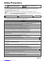 4
4
-
 5
5
-
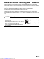 6
6
-
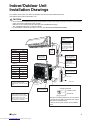 7
7
-
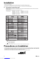 8
8
-
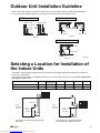 9
9
-
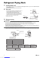 10
10
-
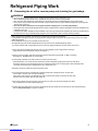 11
11
-
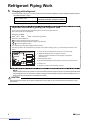 12
12
-
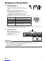 13
13
-
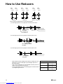 14
14
-
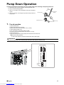 15
15
-
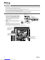 16
16
-
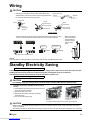 17
17
-
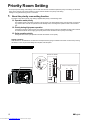 18
18
-
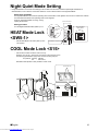 19
19
-
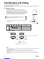 20
20
-
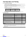 21
21
-
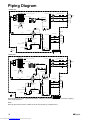 22
22
-
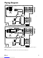 23
23
-
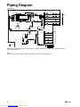 24
24
-
 25
25
-
 26
26
-
 27
27
-
 28
28


Daikin FTXM71M + RXM71M Manualul proprietarului
- Tip
- Manualul proprietarului
în alte limbi
Lucrări înrudite
-
Daikin RXM25M Manualul proprietarului
-
-
Daikin R32 Split Series Ghid de instalare
-
Daikin Altherma 3 R Manual de utilizare
-
-
-
-
Daikin FWF04B7TV1B Ghid de instalare
-
-
Alte documente
-
Tesla TC26P4-0932IA Manual de utilizare
-
Tesla TA36QQCT-1232IAWT Manual de utilizare
-
Sharp AE-A9NR Instrucțiuni de utilizare
-
LG UV18R.N10 Ghid de instalare
-
Mitsubishi Electric PFFY Series Manual de utilizare
-
Whirlpool SPIW318A2WF Air Conditioning Instrucțiuni de utilizare
-
Whirlpool PACW212CO Manualul proprietarului
-
-
DeWalt DPC10RC Manual de utilizare
-
LG LZ-H200GBA2.ENWALEU Manual de utilizare