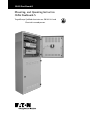
Eaton CEAG DualGuard-S Mounting And Operating Instructions
- Tip
- Mounting And Operating Instructions

CEAG DualGuard-S
Mounting- and Operating Instruction
CEAG DualGuard-S
Targed Group: Qualified electricains acc. EN 50110-1 and
Electrical instucted persons

2
Mounting- and Operating Instruction CEAG DualGuard-S 40071860347 January 2020 www.ceag.de
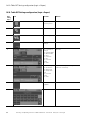
Content
1 Important Notes .................................................................4
1.1 Symbol Key ................................................................4
1.2 Information on the Operating Manual .......................4
1.3 Applicable Documents ...............................................4
1.4 Liability and Warranty .................................................4
1.5 Copyright ....................................................................4
1.6 Spare Parts .................................................................4
1.7 Disposal .....................................................................4
1.8 Safety .........................................................................5
1.9 Intended Use .............................................................5
1.10 Contents of the Operating Manual ..........................5
1.11 Modifying and Retrofitting the Equipment ...............5
1.12 Responsibility of the operator ..................................5
1.13 Occupational Safety ................................................6
1.14 Personal Protective Equipment ................................6
2 Transportation, Packaging and Storage of Batterys .......6
2.1 Safety Notes ............................................................. 6
2.2 Transport over land, enclosed lead battery blocks .....6
2.3 Transportation of enclosed lead Batterys by sea .......6
2.4 Transportation of enclosed lead Batterys by air .........6
2.5 Abbreviations .............................................................6
2.6 Transport Inspection ..................................................7
2.7 Packaging .................................................................7
2.8 Requirements and Prep .............................................7
2.9 Storage Conditions ....................................................7
2.10 Storage.....................................................................7
2.11 Storage Time ............................................................7
3 Set up and Installation
.......................................................8
3.1 Battery rooms, ventilation and
general requirements ................................................8
3.2 Temperature ...............................................................8
3.3 Room dimensions and floor condition ......................9
3.5 Ventilation requirements ............................................9
4 Preparations for battery installation
............................... 10
4.1 Mounting Battery Blocks and
Battery Block Sensors
.............................................10
4.2 Battery sets in parallel installations .........................10
4.3 Mounting positions for AGM blocks .......................11
4.4 Operation .................................................................11
4.5 Maintenance ............................................................11
4.6 General and controls ...............................................11
4.7 Störungen ................................................................12
4.8 Spare parts ..............................................................12
4.9 Ordering Spare Parts ...............................................12
5 Transport, Packaging and Storage ...................................12
5.1 Transport inspection .................................................12
5.2 Packing ....................................................................12
5.3 Storage ....................................................................13
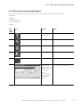
Content
6 Assembly and installation of the DualGuard-S .............13
7 Installation example DualGuard-S .................................19
8 Block Diagram DualGuard-S ............................................20
9 Commissioning and further work ..................................21
10 Luminaire addressing
.....................................................21
11 Checking the wiring
.......................................................21
12 Voltage measurements ..................................................21
13 Insulation measurement
................................................21
14 Check the fuses of the mains or
battery power supply. ...................................................22
15 Switching on the system ..............................................23
16 Device Configuration
......................................................23
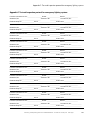
16.1. Table Usergroup .....................................................26
16.2. Table Datendownload via
PC Software and USB Stick ..................................30
16.3. Table Configure basic settings
(login = untrained specialist) .................................30
16.4. Table Circuit Setup
(Login = Uninstructed specialist) ...........................33
16.5. Table configure Luminaire setup
(Login = Uninstructed specialist) ...........................35
16.6. Table configure IO/3PM-IO/TLS Setup
(Login = Uninstructed specialist) ...........................36
16.7. Table configure ACU settings (Login = Expert) ......37
16.8. Table Configure PSU Settings (Login = Expert) .....39
16.9. Table Set Up Web Server (Login Expert) ................40
16.10. Table GLT Settings
configuration (Login = Expert) .............................42
16.11. Table create user groups (Login Expert) ...............43
16.12. Table functional test (Login Operator) .................44
16.13. Table troubleshooting (Login Operator) ...............45
17 General product description DualGuard-S ..................48
18 Overview of assemblies
................................................50
19 HMI Color Touch Screen 4,3“ and 7“
.............................50
19.1. Table Recommendation
Programming and configuration options ................51
20 ACU DG Modul
...............................................................52
21 PSU Module
....................................................................58
22 AC Module
.......................................................................59
23 BCM.1 Module
................................................................60
24 CM.1 1,7 A Lademodule
................................................63
25 CM 3,4 A Lademodule
....................................................63
26 Circuit change over module SKU.1.1 CG-S 4x1,5A .....64
27 Circuit change over module SKU.1.1 CG-S 2x3A .........65
28 Circuit change over module SKU.1.1 CG-S 1x6A .........66
29 Circuit change over module SOU CG-S 2x4 A ..............67
30 CG IV.1 Relay Module .....................................................68
31 CG V.1 Relay Module ......................................................69
32 F3-Remote Control AP and UP ......................................70
Content

3
Mounting- and Operating Instruction CEAG DualGuard-S 40071860347 January 2020 www.ceag.de
Content
Content
33 3-PM Module ...................................................................71
34 3-PM-IO Module ..............................................................72
35 3-PM-IO-INV Module ......................................................73
36 DualGuard-S 28 ...............................................................76
37 DualGuard-S 20 ...............................................................78
38 Connection distributor Mains ........................................80
39 Connection distributor Battery ......................................81
40 DualGuard-S LAD 100 .....................................................82
41 DualGuard-S 12C ............................................................96
42 DualGuard-S 12C6 ........................................................102
43 DualGuard-S 20C6 ........................................................104
44 DualGuard-S 12C4 ........................................................ 110
45 DualGuard-S 4C3 ..........................................................114
46 DualGuard-S US38 .......................................................118
47 DualGuard-S US30 .......................................................120
48 DualGuard-S US 23 ......................................................122
49 DualGuard-S US 15 ......................................................124
50 DualGuard-S US 7 ........................................................126
51 DualGuard-S US SOU2 ................................................128
52 DualGuard-S US SOU1 ................................................129
53 DualGuard-S ESF30 US 15P .........................................130
54 DualGuard-S ESF30 US 30P
.........................................131
55 DualGuard-S ESF30 US SOU5 .....................................132
56 DualGuard-S ESF30 US SOU3
.....................................133
57 DualGuard-S ESF30 US SOU2
.....................................134
58 DualGuard-S ESF30 US SOU1
.....................................135
59 Eaton CCOE Cybersecurity Recommendations
.........136
Appendix A: Overview of pin assignments
.....................139
Appendix B: Overview of pin assignments
.....................140
Appendix D: Position plans of the luminaires
.................141
Appendix E: Installation examples
Monitoring Modules ....................................142
Appendix F: Test and inspection protocol for
emergency lighting systems
.......................143
General Safety instructions - Batterys
.............................144

4
Mounting- and Operating Instruction CEAG DualGuard-S 40071860347 January 2020 www.ceag.de
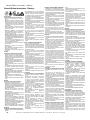
1 Important Notes
1.4 Liability and Warranty
All the information and instructions in this operating manual
were drawn up in accordance with the valid provisions, the
latest state of technology and based on our many years
knowledge and experience.
The operating manual must be kept in direct proximity to
the central battery system, where it must be accessible to
anyone who works on or with the system.
The operating instructions should be read through carefully
prior to performing any work on or with the equipment!
CEAG Notlichtsysteme GmbH accepts no liability and/or
warranty for any defects that could occur in connection with
the delivery and installation of CEAG emergency lighting
systems and lights by virtue of other norms and regulations
that are prescribed in all-in-one packages in connection with
CEAG products. In addition please observe all laws, norms
and guidelines of the country in which the equipment is Atng
set up and operated.
CEAG accepts no liability or warranty for damage or conse-
quential damage caused by
• improper use,
• non-compliance with the regulations and safeguards for
the safe operation of the equipment,
• non-authorized modifications or modifications carried out
by non-specialists to the connections and settings of the
equipment or to programming,
• the operation of unauthorized or unsuitable devices or
groups of devices with the DualGuard-S system.
1.5 Copyright
All material information, texts, drawings, pictures and other
illustrations are protected in accordance with copyright law.
1.6 Spare Parts
Only use the manufacturer‘s original spare parts.
ATTENTION!
Incorrect or faulty spare parts can result in damage, malfunc-
tions, or a complete failure of the equipment. In the event of
the use of unauthorized replacement parts, all guarantee, ser-
vice, compensation and liability claims become null and void.
1.7 Disposal
Packaging materials are not waste material but valuable
assets that can be re-used or recycled.
CEAG has been awarded the recycling certificate issued by
INTERSEROH GmbH. The contract number is 85405. This
guarantees that all registered packaging material is reused
and all the requirements of the Packaging Ordinance are
fulfilled
1 Important Notes
1.1 Symbol Key
Important technical safety information in these operating in-
structions is indicated by symbols. It is imperative that these
safety instructions are adhered to. WARNING! DANGER!
RISK OF INJURY OR DEATH!
ATTENTION! DAMAGE TO
PROPERTY!
This symbol indicates instructions which, if not observed,
may result in damage to health, injury, permanent bodily
injury or death
ACHTUNG! SACHSCHADEN!
This symbol indicates instructions which, if not observed,
can lead to material damage or even a total breakdown of
the system.
NOTE!
This symbol denotes tips and information on practices or how
to handle the described appliances and plant components
that are important for smooth operations.
1.2 Information on the Operating Manual
This operating manual describes how to handle the device
safely and correctly. The safety instructions and information
provided as well as local accident prevention regulations ap-
plicable to the area of operation and general safety measures
must be observed.
Please read the operating manual in full, in particular the
chapter on safety and the relevant safety instructions, before
beginning any work on the equipment.
The illustrations and circuit diagrams in this manual are in
part solely for the purpose of providing visuals for the matters
described in the documents. Whenever:
• exact measurements or
• precise illustrations and circuit diagrams tailored to the
specifics of the location are required,,
the illustrations and plans that have been specially drawn up
for the lighting installation must be followed exactly.
1.3 Applicable Documents
Components from other manufacturers are incorporated into
the equipment (e.g. Batterys). These additional components
are subject to the manufacturer‘s risk assessments. Com-
pliance of these constructions with current European and
national regulations has been certified by the manufacturers
of these components.

5
Mounting- and Operating Instruction CEAG DualGuard-S 40071860347 January 2020 www.ceag.de
1 Important Notes
INTERSEROH collection points are obliged
to dispose of CEAG packaging free of char-
ge.
Batterys and electrical components contain
materials that can result in injury to health
and to damage to the environment if they
are not disposed of properly. Please observe
national guidelines and regulations for the disposal of used
Batterys and electronic components!
1.8 Safety
At the time of its development and production, the device
was manufactured in accordance with the recognized rules
of engineering and is deemed to be operationally safe.
The device may prove hazardous, however, if used by per-
sonnel who have not been properly trained or if used in an
improper or inappropriate manner.
WARNING!
When planning to use lighting equipment with a DualGuard-S
system, first examine whether the electrical equipment in the
area intended for use is adequate. Special conditions (e.g.
potentially explosive atmospheres or areas with aggressive
atmospheres) require special facilities and installations.
Only use the equipment and associated component parts if
free of technical defects, taking into account:
• the safety and hazard information in the assembly and
operating instructions,
• the established operating and safety instructions for the
operator of the equipment,
• the installation and operating data provided in “3 Technical
Data” and the CEAG catalog “Emergency lighting and emer-
gency lighting systems”.
Malfunctions which could impair the function or safety of the
system must be reported immediately to the responsible
departments of the plant management and eliminated.
1.9 Intended Use
The DualGuard-S central battery system serves solely to
provide power, and to monitor and control the emergency
lighting system. Operations are steered by a program. Para-
meterization is carried out exclusively by specialist personnel
with specialized knowledge of the technical principles for the
assembly and operation of a lighting system.
Only use lighting that is either manufactured by CEAG or
which meets the standards and technical specifications
for emergency lighting. You can download the information
needed to assess conformity from our website.
Operational safety is guaranteed only if the systems are used
for the purpose intended.
DualGuard-S devices meet the requirements of EN62034,
“Automated testing systems for battery-operated safety
lighting,” and are classified as Typee PERC.
ATTENTION!
Any use that exceeds the purpose for which the equipment
was intended and/or any other Typee of use of the equipment
that differs from such purpose is prohibited and is deemed
improper use..
1.10 Contents of the Operating Manual
Any person charged with carrying out work on or with of the
system, the operating manual must be read before Start of
work on the battery read and understood have. This shall
also apply if the person concerned has been example has
already worked on similar batteries or has been trained by
the manufacturer.
Changes and conversions to the system
In order to avoid hazards and to secure the optimal perfor-
mance may be achieved at the central battery system no
changes, extensions or conversions have been carried out
which have not been expressly approved by the manufactu-
rer. have been approved.
Any costs incurred in connection with extensions, conversi-
ons, or repairs Work that is not described in these instructions
are specially trained technical and service personnel (of the
manufacturer CEAG or of sales and distribution authorised
by CEAG). service companies) reserved!
1.11 Modifying and Retrofitting the
Equipment
In order to avoid hazards and to ensure the best possible
performance, no modifications, retrofits and add-ons are
permitted to the central battery equipment except where
expressly approved by the manufacturer.
Work involving upgrades, modifications or maintenance that
is not described in this manual must be performed by trained
specialized service personnel
(from the manufacturer CEAG or sales and service firms
authorized by CEAG)!
1.12 Responsibility of the operator
Only authorized and trained electricians may work on and
with the device. The personnel must have been instructed
on any hazards that may occur.
Qualified personnel are defined as persons who are able to
assess the work assigned to them and recognize possible
hazards due to their specialist training, knowledge and ex-
perience as well as knowledge of the relevant regulations.
If the personnel do not have the necessary knowledge,
they must:
• the personnel have been properly and professionally in-
structed,
• Tasks and activities must be precisely defined and under-
stood,
• the activities are carried out under the supervision and
control of competent personnel.

6
Mounting- and Operating Instruction CEAG DualGuard-S 40071860347 January 2020 www.ceag.de
2 Transportation, Packaging and Storage of Batterys
The following safety instructions must therefore always be
observed:
• Never lift loads over persons.
• Always move the device with extreme care and attention.
• Only use lifting tackle and hoisting equipment with suffici-
ent load-bearing capacity.
2.2 Transport over land, enclosed lead bat-
tery blocks
When transported over land, enclosed lead battery blocks
must be in an upright position. Ander the regulations on the
transportation of hazardous goods over roadways (ADR) and
regulations on the transport of hazardous goods by rail (RID),
Batterys that show no signs of damage are not transported as
hazardous goods. They must be secured against short-circuit,
sliding, falling over and damage. Blocks may be stacked in an
appropriate manner, secured to pallets (ADR or RID, Special
Regulation 598). Pallets may not be stackedBlocks with
reservoirs that are leaking or damaged must be packaged
and transported as Class 8 hazardous goods, UN No. 2794.
2.3 Transportation of enclosed lead Batterys
by sea
The following series are not hazardous goods per IMZB, since
they meet IATA Clause A 67:
• Sonnenschein A 400
• Marathon
• Sprinter
2.4 Transportation of enclosed lead Batterys
by air
The following series are not hazardous goods per IATA
Clause A67:
• Sonnenschein A 400
• Marathon
• Sprinter
2.5 Abbreviations
ADR: The European Agreement on the International Transpor-
tation of Dangerous Goods by Road (covering most of Europe)
RID: Regulations concerning the International Transportation
of Dangerous Goods by Rail (covering most of Europe, parts
of North Africa and the Middle East)
IMDG: The International Maritime Dangerous Goods Code
IATA: The International Air Transportation Association (world-
wide)
ICAO: Civil Aviation Organization’s Technical Instructions for
the Safe Transport of Dangerous Goods b
1.13 Occupational Safety
By following the safety information and instructions provided
in this operating manual, injury to persons and damage to ma-
terials can be avoided during work on and with the equipment.
However, the following organizational measures must be
recorded in writing and complied with:
• Informational and reporting requirements (start, duration,
end of the work)
• Safety measures while carrying out the work, (e.g. replace-
ment lighting, deactivation of power supply and secure
against re-start (e.g. removal of fuses, actuator, notice
signs)
• Protective and safety devices for the personnel working
on the equipment
• Protective and safety equipment against hazards posed by
nearby equipment (e.g. safety screen, barriers, securing of
traffic routes)
When working on the system, the ESD protection must be
observed!
The working and safety regulations result from these assem-
bly and operating instructions as well as from the following
• the organisational measures of the plant management
(e.g. see above)
• and from the general and technical guidelines and regula-
tions for accident prevention.
1.14 Personal Protective Equipment
When working on and with the equipment the following
must be worn:
• Protective clothing
• Close fitting work clothing (low resistance to tearing, narrow
sleeves, no rings or other jewelry, etc.).
• Safety shoes
• Electrostatically conductive shoes that comply with Stan-
dard EN 345 that protect against any heavy falling objects.
2 Transportation, Packaging and Storage of
Batterys
2.1 Safety Notes
WARNING! RISK OF INJURY!
Risk of injury from falling parts during transport or during
loading and unloading.
ATTENTION! PHYSICAL DAMAGE!
The battery can be damaged or destroyed by improper
transportation.

7
Mounting- and Operating Instruction CEAG DualGuard-S 40071860347 January 2020 www.ceag.de
2.7 Packaging
2.6 Transport Inspection
Immediately check the delivery upon receipt for complete-
ness and any transport damage.
In the event of clearly identifiable external transport damage,
do not accept delivery or only accept it with reservations.
2.7 Packaging
If no take-back agreement for packaging has been conclu-
ded, separate the materials according to Typee and size and
forward them for use or for recycling.
ATTENTION!
Always dispose of the packaging material in an environ-
mentally safe manner and in accordance with valid local
waste disposal regulations. Where appropriate, contract the
services of a recycling company.
The components included in the delivery can be identified eit-
her by number and Typee or on the basis of a battery drawing.
Do not stack pallets on top of one another.
Always observe the handling instructions on the packaging!
For products labeled “fragile” all measures should be taken
to prevent damage during transport.
2.8 Requirements and Prep
• Prevent or remove soiling on surfaces, dust, etc.
• The storage area should comply with
the following requirements:
• Protect blocks against effects from wea-
ther, dampness or flooding.
• Protect blocks against direct or indirect sunlight.
• Storage rooms for Batterys should be
kept clean, dry and frost free.
• Batterys must be protected against short-circuit
by metal objects or conductive contaminants.
• Batterys must be protected from falling ob-
jects, against falling and tipping over.
2.9 Storage Conditions
Temperatures affect the self-discharge rate. D Storage on pal-
lets packaged with plastic foil is generally allowed. However,
this is not recommended if the room is subject to large tem-
perature fluctuations or if high relative humidity beneath the
foil results in condensation. Over time the condensation can
produce a white film on the lead poles (hydration) resulting
in a high rate of self-discharge produced by leakage current.
The stacking of pallets or devices is not permitted. Avoid
storing unpackaged blocks on surfaces with sharp edges. It
is recommended that the same Typee of storage conditions
be provided for separate batches, pallets or rooms.
2.10 Storage
Prior to assembly, store packaged items unopened and
according to labeling on the exterior.
Only store packages ander the following conditions:
• Never store out-of-doors
• Always store in a dry, dust-free place
It is in the interest of the user that storage time be kept as
short as possible.
2.11 Storage Time
Maximum storage time is 12 months at a temperature of
20°C.
Higher Temperatures result in higher rates of self-discharge
and shorten the intervals
between re-charging.
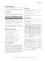
Fig. 1: Sprinter – Residual Capacity in % of C10 versus storage
time at different temperatures
Fig. 2: Marathon – Residual Capacity in % of C10 versus
storage time at different temperatures

8
Mounting- and Operating Instruction CEAG DualGuard-S 40071860347 January 2020 www.ceag.de
Positioning and installation
Measures during Storage
Appropriate storage, based on the FIFO (“first-in, first out”)
method avoids excess storage time.
If the blocks need cleaning, do not use a cleaning agent
and instead use cotton cloths soaked in water without any
additives.
For longer periods of storage it is recommended that open-
circuit voltage be inspected at the following intervals
• Storage at 20°C: after 6 months, then every 3 months.
• Storage at 30°C: after 4 months, then every 2 months.
Recharging is necessary if open-circuit voltage is < 2.11 V/Z
Continuous charging *) is considered a possibility if the
measured open-circuit voltage is < 2.11 volts per cell.
*) Continuous charging means maintenance charging at low
rates, approximately equal to self-discharge and sufficient
to keep the battery fully charged. It can be carried out either
by IU charging (normal trickle charge mode) or I charging
(constant current) with limited current.
Continuous charging during storage
Depending on the charger, the charging time must be ex-
tended by 24 stands for each 0.04 V below the maximum
voltage. The minimum voltage is the lowest limit.
At temperatures < 15 °C a charging time of 20 stands is
recommended.
Positioning and installation
Constant voltage charge (IU charge)
Tempera-
ture
Max.
Voltage per
cell
Min.
Voltage per
cell
Max. cur-
rent
Charging
time at
max. vol-
tage
20 °C 2,38 V 2,27 V 0,2 C10 24 h
25 °C 2,35 V 2,25 V 0,2 C10 24 h
30 °C 2,32 V 2,22 V 0,2 C10 24 h
Tab. 1: Values for constant voltage charge (valid for Marathon L)
Tempera-
ture
Max.
Voltage per
cell
Min.
Voltage per
cell
Max. cur-
rent
Charging
time at
max. vol-
tage
20 °C 2,40 V 2,29 V 0,2 C10 24 h
25 °C 2,37 V 2,27 V 0,2 C10 24 h
30 °C 2,35 V 2,25 V 0,2 C10 24 h
Tab. 2: Values for constant voltage charge (valid for Sprinter)
3 Set up and Installation
SAFETY NOTICE WARNING!
RISK OF INJURY!
Improper installation and installation can lead to serious per-
sonal injury and/or damage to property. This work may there-
fore only be carried out by authorized, instructed personnel
familiar with the operation of the device and in compliance
with all safety regulations.
• Ensure sufficient freedom of movement.
• Ensure order and cleanliness at the workplace. Loose or
loose components and tools are sources of accidents!
3.1 Battery rooms, ventilation and general
requirements
General: This is only a guideline and contains excerpts from
national and international standards. See DIN EN 50272-2
for more detailed information. Please also follow the user
instructions and installation guide.
3.2 Temperature
• AGM Batterys are designed to operate in the -15°C and
+55°C temperature ranges..
• The battery room temperature should be between +10 °C
and +30 °C. The battery should be operated in a tempera-
ture range of -15 °C and +55 °C.
• The optimum temperature is the nominal temperature of
20 °C.
• Higher temperatures reduce the design Above 40 °C there
is a risk of the „thermal runaway effect“.
Lower temperatures reduce available capacity and extend
recharge time.

9
Mounting- and Operating Instruction CEAG DualGuard-S 40071860347 January 2020 www.ceag.de
3 Set up and Installation
• Below approx. -8 °C there is a risk of freezing, but this de-
pends on the state of charge. Nevertheless, it is possible
to operate the Batterys at low temperatures ander certain
conditions.
• Battery temperature affects available capacity.
• The temperature difference between blocks in a battery
string must not exceed 5 °C (5 Kelvin).
3.3 Room dimensions and floor condition
The floor of the battery rooms should be level and suitable
for carrying the weight of the battery.
From DIN EN 50272-2: The floor area where a person is within
arm‘s reach of the battery must be conductive enough to
prevent electrostatic charging. The leakage resistance to an
earthed point, measured according to IEC 61340-4-1, must
be less than 10 MOhm.
On the other hand, the floor must be sufficiently insulated
for the safety of persons. Therefore, the resistance of the
floor to leakage from an earthed point, measured according
to IEC 61340-4-1, must be:
• at nominal battery voltage 500 V: 50 kOhm R 10 MOhm and
• for battery voltage > 500 V: 100 kOhm R 10 MOhm.
Note 1: In order for the first part of the requirement to take
effect, maintenance personnel must wear electrostatically
conductive shoes near the battery. The footwear must comply
with EN 345.
Note 2: Arm range: 1,25 m distance (For definition of arm
range see HD 384.4.41.)...“.
Ventilation inlets and outlets: The arrangement for circulation
should be as shown below
3.4 Ventilation
To avoid explosions, battery rooms must be ventilated in
accordance with DIN EN 50272-2 to dilute gas (hydrogen and
oxygen) which is released during charging and discharging.
The electrical installation does not have to be EX-protected
for this.
It must be designed for humid room conditions.
Never install the battery hermetically sealed.
Spark-forming parts must have a safety distance from the cell
or block openings (valves with sealed Batterys) in accordance
with DIN EN 50272-2.
Heating elements with open flames or glowing surfaces are
prohibited. The temperature of heating elements must not
exceed 300°C.
3.5 Ventilation requirements
Ventilation and exhaust of electrical operating rooms
Dimensioning of ventilation according to DIN EN 50272-2
(The well-known DIN VDE 0510 Part 2 has been invalid since
01.04.2003.)
The air volume flow required to ventilate a battery room
or battery container must be calculated according to the
following equation:
Q = 0.05 x n x Igas x CN x 10-3 [m3/h]
Q = the required air volume flow, in m3/h
0.05 = fixed factor
n = number of cells
Igas = the current which causes the gas development in mA
per Ah corresponds to 8 mA per Ah at high charge for sealed
lead acid Batterys.
CN = nominal capacity C10 at 20 °C for lead Batterys
Calculation example for the required air volume flow of a
DualGuard-S with 155.6 Ah lead battery sealed:
Q = 0.05 x n x Igas x CN x 10-3
Q = 0.05 x 108 x 8 x 155.6 x 10-3 m3/h
Q = 6.72 m3/h
To ensure this air volume flow of 6.72 m3/h, the supply
and return air openings in the battery rooms must have the
following minimum cross-sections in accordance with DIN
EN 50272-2.
Ventilation cross-sections of the supply and return air ope-
nings:
A - 28 x Q
A - 28 x 6.72 m3/h
A - 188,21 cm2
The required ventilation openings in the F90 walls are to
be secured in terms of building protection, e.g. by: F90 fire
dampers.

10
Mounting- and Operating Instruction CEAG DualGuard-S 40071860347 January 2020 www.ceag.de
4 Preparations for battery installation
As can be seen from the calculation, no complex technical
ventilation (e.g. explosion-proof fan) is required even when
using the largest battery.
Furthermore, due to the low-maintenance, leak-proof lead
Batterys used, no special constructional requirements such
as electrolyte-resistant floor or floor covering (tiles, door sill)
etc. have to be met.
Sealed lead-acid Batterys can always be operated in any
position (except head position).
Determination of the aeration and ventilation of electrical
operating rooms in accordance with DIN EN 50272-2 (Cal-
culated for heavy charge!):
Batterykapazität in Ah
C10 At 1,8 V/Z and +20°C
5.5 8.5 14.0 23.3 32.0 39.8 50.4 53.7 66.2 85.7 89.4 106.0 118.0 143.1 155.6 178.8 195.4 245.0 268.2 308.0 357.6
Air volume flow req. for the
ventilation of the place of
installation [m
3
/h]
0.24 0.37 0.60 1.01 1.38 1.72 2.18 2.32 2.86 3.70 3.86 4.58 5.10 6.18 6.72 7.72 8.44 10.58 11.59 13.31 15.45
Vent cross-section
of the air inlets and
outlets of the place of
installation [cm
2
]
6.65 10.28 16.93 28.18 38.71 48.14 60.96 64.96 80.08 103.66 108.14 128.22 142.73 173.09 188.21 216.28 236.36 296.35 324.41 372.56 432.55
4 Preparations for battery installation
Check all blocks by measuring the open-circuit voltage.
6 Volt block: U ž 6.33 V
12 volt block: U ž 12.66 V
• When measuring the open-circuit voltage, the correct
polarity (possible incorrect installation) must be observed
at the same time.
• If drawings were supplied by CEAG Notlichtsysteme
GmbH, these must be observed during installation.
• The frames must be horizontally aligned and load-bearing.
For rack mounting from 4 levels and 2 rows or 5 levels
and 3 rows, the rack should also be firmly anchored in the
battery room.
• Racks and cabinets should provide adequate ventilation
above and below to allow sufficient dissipation of the
heat generated by Batterys and their charging system.
The distance between cells or blocks should be 10 mm,
but at least 5 mm.
4.1 Mounting Battery Blocks and Battery
Block Sensors
Insulated tools must be used for the assembly work. Wear
rubber gloves, goggles and protective clothing (incl. safety
shoes). Remove metal objects such as watches or jewellery.
Mount the supplied battery block sensors Typee BBS, pole
covers for insulation of the battery poles with the battery
connectors. Tighten the battery connector with an insula-
ted torque wrench. The following torques apply to screw
connections:
• G-M5 flat terminal: 5 ± 1 Nm
• M6 threaded bolt: 6 ± 1 Nm
• M6 threaded hole: 11 ± 1 Nm
• M8 threaded bolt: 8 ± 1 Nm
• M8 threaded hole: 20 ± 1 Nm
• M12 threaded bolt: 25 ± 1 Nm
• Inch 10-32x0.425: 6 ± 1 Nm
After completion of the installation work, thinly coat the
connection surfaces with the supplied pole grease.
This measure prevents corrosion, but is not absolutely
necessary.
Check total battery voltage. It should correspond to the
number of blocks connected in series.
The open-circuit voltage of individual cells should not vary
more than 0.02V between them. The following maximum
deviations are permitted for block Batterys:
• 6 V - Blocks: 0.04 V
• 12 V - Blocks: 0.05 V
Mount the supplied terminal covers to insulate the battery
terminals.
4.2 Battery sets in parallel installations
Conditions and characteristics for 2 to 4 strings in parallel:
To connect the battery strings in parallel, the battery connec-
tion distributor Typee BAE with integrated current shunt per
string must be used for battery string monitoring.
• The cable connectors for the positive and negative poles
of each string must have the same length.
• The minimum cable cross section for the end connectors
of a string is 25 mm
2
per 100 Ah string capacity.
• The end connector cables must end on a copper bar with at
least 100 mm
2
per 100 Ah line capacity and at the smallest
possible distance.
• Each string has a fuse.

11
Mounting- and Operating Instruction CEAG DualGuard-S 40071860347 January 2020 www.ceag.de
4 Preparations for battery installation
• The strings must have the same number of cells and
temperature.
Ander these conditions a parallel connection of up to 4
strings is possible. The discharge data refer to the end poles
of each string.
The lead battery Typee can also vary as long as the required
charging voltage (V/cell) per string is fulfilled.
First pre-assemble each string individually. Make sure that
the strings have approximately the same charge state, i.e.
similar open-circuit voltages. Only then should the strings
be connected in parallel.
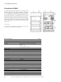
4.3 Mounting positions for AGM blocks
The following figures show possible installation positions for
sealed AGM blocks
4.4 Operation
SAFETY INSTRUCTIONS WARNING!
RISK OF INJURY!
Improper installation can lead to serious personal injury and/
or damage to property. The battery may only be operated by
authorized and instructed personnel familiar with the operati-
on of the device and in compliance with all safety regulations.
Before starting work:
• Before starting work, check the battery for completeness
and technically perfect condition.
• Ensure sufficient freedom of movement. ATTENTION!
Please do not stick over the battery valve covers when stik-
king on the battery block sensors or battery block numbering!
During operation:
• In case of malfunctions, first switch off the battery and
then secure it against Atng switched on again.
Always wear the battery when working on and with it:
• Safety shoes for protection against heavy falling parts and
slipping on non-slip surfaces.
4.5 Maintenance
SAFETY INSTRUCTIONS WARNING!
RISK OF INJURY!
Improper maintenance work can lead to serious personal
injury and/or damage to property. This work may only be
carried out by authorized and instructed personnel familiar
with the operation of the battery and in compliance with all
safety regulations.
MAINTENANCE ATTENTION!
Never use synthetic cloths or sponges to clean the blocks,
only water (damp cloths) without additives
4.6 General and controls
Regular checks and maintenance are necessary in relation to:
1. the specified charging voltages and currents,
2. the unloading conditions,
3. the temperature distributions,
4. the storage conditions,
5. the cleanliness of the battery and equipment,
6. and other conditions affecting the safety and service life of
the battery (e.g. ventilation of the battery compartment).
Sealed lead-acid Batterys do not require refilling with water.
That is why they have been described as „maintenance-
free“. They are sealed by overpressure valves which cannot
be opened without destruction. This is the reason for the
definition of Valve-Regulated Lead-Acid Batterys.
Sealed batteries require the following checks:
Keep the battery clean to avoid leakage currents. Plastic parts
of the battery, especially the vessels, must be cleaned with
clear water without additives.
Measure and record at least every 6 months:
• Battery voltage
• Voltage of individual cells/blocks (approx. 20%)
• Surface temperature of individual blocks
• battery temperature
The optional battery monitoring system meets these
requirements automatically. See separate instruction
manual for battery block monitoring.
not OK

12
Mounting- and Operating Instruction CEAG DualGuard-S 40071860347 January 2020 www.ceag.de
5 Transport, Packaging and Storage
Annual visual inspections:
• Screw connections (check unsecured screw connections
for tight fit)
• Battery installation and accommodation
• ventilation
If block voltages are outside the specified range or if the
surface temperatures of different blocks differ by more than
5 K, customer service should be requested.
in operation since 6-V-blocks 12-V-blocks
6.81 V 13.62 V
< 6 month 6.60 - 7.19 V 13.33 - 14.16 V
> 6 month 6.64 - 7.16 V 13.38 - 14.11 V
Tab. 7: Permissible range of float charge voltages
4.7 Störungen
Verhalten At Störungen
Hierzu finden Sie in der Montage- and Betriebsanleitung
ZentralBatterysystem entsprechende Angaben.
4.8 Spare parts
Only use original spare parts from the manufacturer.
ATTENTION!
Wrong or faulty spare parts from other manufacturers can
cause serious damage to the battery. Ensure the same char-
ging state when changing the battery blocs.
RECOMMENDATION:
not more than 25% of the battery packs of a battery set
should be replaced. Therefore with 18 packs not more than
5 packs should be replaced.
When 50% of the expected service life is exceeded and
single battery packs fail, the complete set should be replaced
4.9 Ordering Spare Parts
Please state the following when ordering spare parts:
• order number
• rated capacity
• Typee
In case of complaints you need a RMA - number from us. For
further information see www.ceag.de!
5 Transport, Packaging and Storage
SAFETY NOTES!
WARNING! RISK OF INJURY! There is a risk of injury when
transporting or loading due to falling parts.
ATTENTION! DAMAGE TO PROPERTY!
Batterys will be destroyed or damaged by improper transport.
The following safety instructions must therefore always be
observed:
• Never lift loads over persons.
• Always move the device with the greatest care and caution.
• Only use suitable slings and hoists with sufficient load-
bearing capacity.
• Always transport and store the DualGuard-S system upright
(markings and tilt indicator on the packaging).
• Avoid ingress of dust and moisture during transport.
• Ensure that all transport routes are clear (sufficient width
and clear height for all transport movements). Sufficient
space is available for people to move aroand if loads tilt or
slip. Have sufficient load-bearing capacity (for load, pak-
kaging and means of transport). The means of transport
used cannot be overstrained with regard to gradients and
the nature of the subsoil.
• Only use means of transport (e.g. lift trucks, forklift trucks,
etc.), slings (traverses, chains, ropes, etc.) and securing
devices (wedges, squared lumber, guide, tensioning, se-
curing ropes, etc.) in perfect technical condition and with
sufficient load-bearing capacity.
• Observe all instructions regarding transport conditions,
transport position, attachment points on the transport
packaging or on the device / switch cabinet.
For the execution of transport work, use only personnel who
are familiar with the usual methods and signals and are able
to carry out the transport work professionally, safely and in
accordance with the risks involved.
5.1 Transport inspection
Check delivery immediately upon receipt for completeness
and transport damage. In case of externally recognizable
transport damage, do not accept the delivery or accept it
only ander reservation.
5.2 Packing
If no return agreement has been made for the packaging,
separate materials by Typee and size and return them for
further use or recycling.

13
Mounting- and Operating Instruction CEAG DualGuard-S 40071860347 January 2020 www.ceag.de
6 Assembly and installation of the DualGuard-S
CAUTION!!
Always dispose of packaging materials in an environmentally
friendly manner and in accordance with the applicable local
disposal regulations. If necessary, commission a recycling
company.
Observe the handling instructions on the packaging!
5.3 Storage
Packages must be closed until assembly and stored in
accordance with the installation and storage markings on
the outside.
Packages should only be stored ander the following condi-
tions:
• Do not store outdoors
• Dry and dust-free storage
• The storage location should be clean and tidy.
• The storage time should be as short as possible in the
interest of the user (FIFO method).
• The stacking of pallets or equipment is not permitted.
6 Assembly and installation of the DualGu-
ard-S
WARNING! DANGER OF INJURY!
Improper installation and installation can lead to serious per-
sonal injury and/or damage to property. This work may there-
fore only be carried out by authorised, instructed personnel
familiar with the operation of the device and in compliance
with all safety regulations.
• Ensure sufficient freedom of movement.
• Pay attention to cleanliness and order at the workplace. Loo-
se or loose components and tools are sources of accidents!
• Ensure sufficient cooling of the system
• Observe ambient conditions in accordance with protec-
tion Typee and class (with regard to protection against
contact with live parts and ingress of dust, foreign bodies
or moisture).
• The cable length in a lighting circuit up to the last luminaire
in the circuit must not exceed the permissible cable length.
Special requirements for distributors with functional
integrity Typee DualGuard-S ESF... :
The enclosures must be adapted to the masonry in such a
way that the enclosures are horizontal. The masonry must
be designed to withstand fire for at least 30 minutes. The
fire resistance period of the masonry must not be affected
by the installation.
The systems illustrated in these installation and operating
instructions may differ in their modular configuration when
delivered. Special features of customer-specific designs are
described in the project documents to be ordered separately.
WARNING!
Work on the general supply network and the laying of load,
signal and control lines as well as the connection of the
battery power supply may only be carried out by qualified
electricians with special knowledge of the legal and technical
principles for the installation and operation of emergency
lighting systems. This also applies to the initial commissioning
or re-commissioning of the emergency lighting system or the
DualGuard-S system.
Take all necessary measures for occupational safety!
In addition to compliance with general technical standards
and procedures, this includes, in particular, compliance with
all special notes and instructions.
NOTE!
All connecting cables may only be laid in accordance with
the relevant electrical engineering directives and standards
(e.g. DIN VDE 100 series of standards).
In addition, observe all national directives and regulations of
the country in which the system is installed and operated.
Secure all cable inlets and outlets of the DualGuard-S cabi-
net against mechanical damage to the cables or moisture
ingress using the M cable glands or rubber seals provided
for this purpose.

14
Mounting- and Operating Instruction CEAG DualGuard-S 40071860347 January 2020 www.ceag.de
6 Assembly and installation of the DualGuard-S
ATTENTION!
Short-circuits and incorrect polarity can damage the battery
bank or the installations of a DualGuard-S system.
When interfering with the electrical system (e.g. connecting
control or signal lines) or electronics (e.g. plugging or unplug-
ging modules in the control cabinet), the ESD protection must
be observed! Never switch the mains or battery power supply
on or off ander load. In both cases, the system must have
been blocked beforehand via the control unit.
DANGER!
If the Batterys or battery-powered parts of the system are
handled improperly, there is a risk of injury or death due
to high currents or electric arcs, which can occur briefly at
battery discharge.
It is essential that you observe the instructions in this manual
for disconnecting or connecting the Batterys (see „Connec-
ting the battery power supply“).
Ensure that the polarity of the battery banks (battery cabinets
/ racks) is correct.
ATTENTION!
Short circuits and incorrect polarity can damage the battery
bank or the installations of a DualGuard-S system.
At interventions in the electrics (e.g. connection of control or
signal lines) or electronics (e.g. plugging or pulling modules in
the switch cabinet), the ESD protection must be observed!
Never switch the mains or battery power supply on or off
under load. In some cases, the system must have been
blocked beforehand by the control unit.
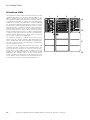
Assembly
Requirements for the work surface / installation site:
Installation on level groand with sufficient bearing capacity.
The installation site must be levelled horizontally.
Holes are provided in the floor plate for fastening to the floor
or screwing to a base.
Installation
Disconnect all connecting cables (mains and battery power
supply) from the power supply and secure them against
unintentional reconnection (e.g. removal of all fuses and
corresponding protection of the distributor of the general
mains supply and the battery bank with information signs
and/or locks).
Install the connecting cables (mains and battery power supp-
ly) with sufficient length reserve up to the installation location
of the DualGuard-S cabinet. Carry out this work properly and
professionally in accordance with the applicable directives
and standards.
Secure all cable entries with the M cable glands provided.
If possible, lay the connecting cables in the cable areas of
the control cabinet.
NOTE!
In this illustration, outgoing cables for mains and battery
power supply of substations were attached to the cabinet
wall on C-rails (item no. 40071347126) with corresponding
cable clamps. Do not leave any connecting cables tempo-
rarily loose!
Later additions or conversions of the system equipment are
possible, but the description of such interventions in the
internal equipment is not part of these instructions, as such
work is reserved for specially trained CEAG personnel!
The installation of general and emergency lighting is not
covered by these instructions.
Install, install and connect the lighting equipment in accor-
dance with the relevant electrical engineering directives and
standards. In addition, observe all directives and regulations
of the country in which the system is installed and operated.

15
Mounting- and Operating Instruction CEAG DualGuard-S 40071860347 January 2020 www.ceag.de
6 Assembly and installation of the DualGuard-S
Mains connection
Connecting the mains power supply
Power is supplied via the general mains supply or via the
Batterys of a battery bank (battery cabinet or rack).
Example DualGuard-S 12C:
1 phase mains connection to load disconnector (1) and PE
terminal
1-phase mains connection of a substation to load discon-
nector (1) and PE.
Make sure that the mains cable is disconnected. Connect
the 230V mains cable to the fuse isolator (1).
Mains connection of sub-stations
If the substations are to be supplied via the power supply of
the associated DualGuard-S system, an outgoing distributor
for three 1-phase or one 3-phase power supply must be
available for connection.
• Make sure that the system and the supply lines are dis-
connected and secured!
• Connect the protective conductor to the PE terminal block.
• Connect the neutral conductor to the N-terminal block.
• Connect the L-conductor to the terminals of the outgoing
distributor.
NOTE!
To make work easier, outgoing distributors can be removed
from the busbar to the front when the lock on the upper
housing wall is released. Once the outgoing cables have
been connected, the outgoing distributor can be placed back
on the busbar with slight pressure and snapped into place.
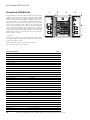
Battery Supply Connections
Please observe the battery manufacturer‘s data sheets
enclosed with the CEAG battery banks!
Observe the legal regulations and rules which apply at the
place of operation of the emergency lighting system!
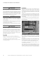
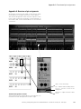
NOTE
CEAG battery cabinets are
equipped as standard with a
cabinet terminal block (see
illustration) on which the con-
necting cables (+/-) for the
battery power supply and a
temperature sensor (F+/F-)
are connected. The PE con-
nection is used to protect live parts of the battery cabinet.
In the case of battery racks and battery cabinets, the con-
necting cables to the end poles of the interconnected Batte-
rys are not included in the scope of delivery. In the case of
battery racks, the terminal block is not included in the scope
of delivery.
CEAG recommends the installation of a battery supply dis-
tributor with circuit breaker, string monitoring and fuses for
the battery circuit (see „Installation Instructions for Battery
Power Distributors“), which enables safe disconnection
of the terminals for the connecting cables leading to the
DualGuard-S control cabinet.
The battery connection cables (for the DualGuard-S control
cabinet and its substations) must be laid in accordance with
DIN VDE 0100T520 to be protected against groanding and
short circuits!
Ensure that the cables have a conductor cross-section that
is suitable for the expected current flows to the connected
loads.
Only one temperature sensor (F+ / F-) and up to four battery
1
1

16
Mounting- and Operating Instruction CEAG DualGuard-S 40071860347 January 2020 www.ceag.de
6 Assembly and installation of the DualGuard-S
strand monitors may be connected to the Battery Control
Module BCM.1. Its cable must be routed separately to the
battery bank. A 2- to 8-core cable can be used for this pur-
pose, with a cross-section of 0.5 mm2 for lengths < 50 m.
WARNING!
The battery power supply is nominal 216 V DC! Improper
handling can lead to life-threatening electric shocks or burns
(due to arcing)!
Ensure that the polarity of the battery banks is correct.
Switch off all connected consumers beforehand („Block
the system via the colour touch display“) so that no elec-
tric arcs occur when the battery circuit is disconnected (or
connected)!
NOTE!
Sequence of connection:
• Connect the cable marked „+“ to the positive terminal of
the battery bank.
• Connect the cable marked „-“ to the negative terminal of
the battery bank.
• When disconnecting the battery power supply, the reverse
order applies.
Connecting the Battery Supply
The connecting cables for the battery power supply supply
supply the modules of the DualGuard-S (or sub-distribution
boards) and the emergency lighting circuits (switched via
the SKU.1.1 modules). Furthermore, the charging of the
connected battery banks is controlled via the BCM.1 module.
Only when the control is blocked may the connections of the
battery power supply be switched off without danger via the
load-break switch (Batt). Charging modules and all circuits
of the SKU.1s are then disconnected only after the mains
power supply has been switched off. Please note that the
connection cables from the battery bank (battery cabinet/
frame) may still be live!
NOTE!
The connections (+ / -) are accessible when the moving part
of the switch-disconnector (Batt) has been removed (removal
is analogous).
Connect the cables for the battery power supply of the
DualGuard-S switch cabinet:
Make sure that the system and the supply lines are discon-
nected!
Connect the positive conductor to the positive terminal of
the switch-disconnector.
Connect the negative conductor to the negative terminal of
the switch-disconnector.
Pos. 1: Mains connection
Pos. 2: Battery connection
Pos. 4: Shunt for battery current measurement
Pos. 5: Sub-distributor connection
Connection of the battery supply of a sub-
station
Substations are supplied via the power supply of the asso-
ciated DualGuard-S system. An outgoing distributor can be
used for a battery power supply. The middle terminal and
associated fuse are not used.
NOTE!
To make work easier, outgoing distributors can be removed
from the busbar to the front when the lock on the anderside
of the housing is released.
Once the outgoing cables have been connected, the out-
going distributor can be reattached to the busbar with slight
pressure and snapped into place.
1
5
2/4

17
Mounting- and Operating Instruction CEAG DualGuard-S 40071860347 January 2020 www.ceag.de
6 Assembly and installation of the DualGuard-S
Position of the switch-disconnector (1) for the battery power
supply with pos. 2: Outlet distributors (Batt). Observe the
warning notices!
Connect the lines for the battery power supply of a substa-
tion:
Make sure that the system and the supply lines are discon-
nected and secured!
Lay the supply lines to/from the DualGuard-S switch cabinet
and in its cable ducts and to/from the substation switch
cabinet.
Connect the positive conductor to the positive terminal of
the outgoing distributor.
Connect the negative conductor to the negative terminal of
the output distributor.
When retrofitting fuse elements, the enclosed sticker must
be applied with the correct polarity to identify the connections
as shown in the illustration.
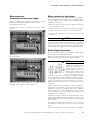
Connection of a temperature sensor
A temperature sensor (for temperature monitoring of the
battery bank) of the DualGuard-S central battery system is
mandatory for emergency lighting systems with a central
battery. Connection to the charging unit is made in the control
cabinet via terminals (1) F+ and F- on the 3-level installation
terminals with spring-cage connection.
Lay the temperature monitoring cable between the battery
bank and the DualGuard-S switch cabinet and connect it to
the switch cabinet via its 3-storey installation terminals with
tension clamp connection.
Position of the terminal block for connecting a temperature
sensor
ACHTUNG!
A shielded 2-wire cable must be used as the connecting
cable for the temperature sensor. In the system, the shield
must be connected to the protective conductor terminal on
one side via a shield quick connector.
1
2

18
Mounting- and Operating Instruction CEAG DualGuard-S 40071860347 January 2020 www.ceag.de
6 Assembly and installation of the DualGuard-S
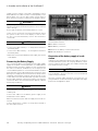
Connection of a battery string Monitoring
Connection to the BCM.1 module is made in the control
cabinet via terminals (1-4) I+ and I- on the 3-level installation
terminals with spring-cage connection.
Lay the line for string monitoring between the battery bank
and the DualGuard-S control cabinet and connect it in the
control cabinet via its 3-level installation terminals with ten-
sion clamp connection.
Position of the terminal block for connecting a temperature
sensor
ATTENTION!
A shielded 2-8-wire cable must be used as the connecting
cable for string monitoring. In the system, the shield must
be connected to the protective conductor terminal on one
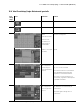
side via a shield quick connector.
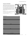
Connection and assembly of internal mod-
ules
All modules for the DualGuard-S control cabinet are mounted
on a so-called carrier (BGT). These plug-in sockets contact
the module at the installation location; plastic snaps secure
the position of the module. The required mains or battery
power supply for the modules is also provided via these
plug-in sockets.
For easy assembly/disassembly, these modules are connec-
ted via pluggable screw terminal blocks that can be plugged
or unplugged at the front of the modules. The connecting cab-
les of these screw terminals are laid on the terminal strip in
the upper area of the control cabinet. The assignment is made
via numerical codes on the module and on the terminal block.
External supply and discharge lines are connected via this
terminal block series in the upper area of the control cabinet.
HINWEIS
The assignment of the circuit numbers used in the touch
display and the displayed switching outputs of the SKU.1s
is made by selecting the slots on the subracks. Replaced
SKU.1s must be re-registered via the touch display.
ACHTUNG!
SKU.1 modules must never be plugged or unplugged in
the On switching state! Deactivate an SKU.1 module via
the touch display before pulling or inserting it, e.g. for
test or inspection purposes.
The controller must be blocked for disassembly or con-
version work to prevent activated circuits from Atng
switched on when an SKU.1 module is plugged on.
BGT 2 equipped with modules and with 2 free slots

19
Mounting- and Operating Instruction CEAG DualGuard-S 40071860347 January 2020 www.ceag.de
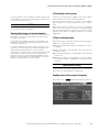
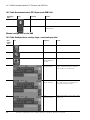
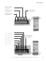
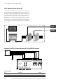
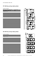
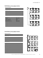
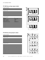
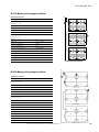
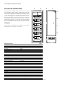
7 Installation example DualGuard-S
7 Installation example DualGuard-S
HMI
01
U2
02
U3
03
U1
U4
04
Stromkreisumschaltung
CG-S 4x1,5A
SK 1
SK 2
SKU
SK 3
F1-0
SK1
F1-U
F2-0
SK2
F2-U
F3-0
SK3
F3-U
10AT
2,5AT 2,5AT 2,5AT
SK 4
F4-0
SK4
F4-U
2,5AT
+24V
-24V
A
B
+ -
L
N
PSU
+.Batt
-.Batt
+.2
-.2
+.1
-.1
2
1
11
22
21
12
+24
-24
+CCB
-CCB
31
-
+
32
I+
I-
I+
I-
I+
I-
I+
I-
F+
F-
BCM.1
K1.11
BDM
K2.14
K2.11
K1.14
+24
-24
H
L
CM1,7A
+.Batt
-.Batt
+CCB
-CCB
+CCB
-CCB
L
N
H
L
Sh1
+24.1
-24.1
A
B
Sh2
+24.2
-24.2
IN1.1
IN1.2
IN2.1
IN2.2
IN3.1
IN3.2
IN4.1
IN4.2
IN5.1
IN5.2
IN6.1
IN6.2
K1.COM
K1.NO
K1.NC
K2.COM
K2.NO
K2.NC
K3.COM
K3.NO
K3.NC
K4.COM
K4.NO
K4.NC
HMI
ETN
+24.3
-24.3
IN7.1
IN7.2
IN8.1
IN8.2
K5.COM
K5.NO
K6.COM
K6.NO
ACU
H
L
A
B
L1
L2
L3
N
PE
B+
B-
BBS
B+
B-
BBS
B+
B-
BBS
B+
B-
BBS
B+
B-
BBS
B+
B-
BBS
B+
B-
BBS
B+
B-
BBS
B+
B-
BBS
B+
B-
BBS
B+
B-
BBS
B+
B-
BBS
B+
B-
BBS
B+
B-
BBS
B+
B-
BBS
B+
B-
BBS
B+
B-
BBS
B+
B-
BBS
L.1
N.1
L.2
N.2
L.3
N.3
L.4
N.4
L.5
N.5
L.6
N.6
L.7
N.7
L.8
N.8
+24
+24
-24
-24
RS485 IN
RS485 IN
RS485 OUT
RS485 OUT
3-PM-IO
N
L3
L2
L2
L1
L1
1
2
3
S
S
3-PM

20
Mounting- and Operating Instruction CEAG DualGuard-S 40071860347 January 2020 www.ceag.de
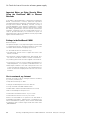
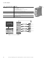
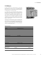
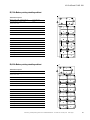
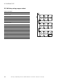
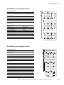
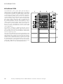
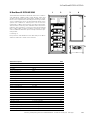
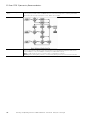
8 Block Diagram DualGuard-S
8 Block Diagram DualGuard-S
3-PM
F3 Fernanzeige AP
SOU CG-S 2x4 A
US
3-PM-IO
3-PM-IO-INV / TLS
TFT-Touch-Display
AC-Trafo
(Module)
PSU
CM 3,4 A
BBS.
Batterieblock
Sensoren
BDM.
Batterie Data Modul
für separate Montage
Baugruppenträger
Stromkreismodule
Baugruppenträger
Lademodule
CM.1 1,7A
CG IV.1/V.1
Relaismodul
SKU.1 CG-S 4x1,5 A
ACU
DG
BDM
24V Stromschleife
RS 485 Bus
ACU DG Bus
24 V DC
L/N 230 V
L/N 250 V
Ethernet
CCB-BUS
Temperatur Sensor
Shunt ( Battery-Line)
L
L1
L2
L3
N
+
-
CCB-Bus
N
+
-
Bus
RS485
Pagina se încarcă...
Pagina se încarcă...
Pagina se încarcă...
Pagina se încarcă...
Pagina se încarcă...
Pagina se încarcă...
Pagina se încarcă...
Pagina se încarcă...
Pagina se încarcă...
Pagina se încarcă...
Pagina se încarcă...
Pagina se încarcă...
Pagina se încarcă...
Pagina se încarcă...
Pagina se încarcă...
Pagina se încarcă...
Pagina se încarcă...
Pagina se încarcă...
Pagina se încarcă...
Pagina se încarcă...
Pagina se încarcă...
Pagina se încarcă...
Pagina se încarcă...
Pagina se încarcă...
Pagina se încarcă...
Pagina se încarcă...
Pagina se încarcă...
Pagina se încarcă...
Pagina se încarcă...
Pagina se încarcă...
Pagina se încarcă...
Pagina se încarcă...
Pagina se încarcă...
Pagina se încarcă...
Pagina se încarcă...
Pagina se încarcă...
Pagina se încarcă...
Pagina se încarcă...
Pagina se încarcă...
Pagina se încarcă...
Pagina se încarcă...
Pagina se încarcă...
Pagina se încarcă...
Pagina se încarcă...
Pagina se încarcă...
Pagina se încarcă...
Pagina se încarcă...
Pagina se încarcă...
Pagina se încarcă...
Pagina se încarcă...
Pagina se încarcă...
Pagina se încarcă...
Pagina se încarcă...
Pagina se încarcă...
Pagina se încarcă...
Pagina se încarcă...
Pagina se încarcă...
Pagina se încarcă...
Pagina se încarcă...
Pagina se încarcă...
Pagina se încarcă...
Pagina se încarcă...
Pagina se încarcă...
Pagina se încarcă...
Pagina se încarcă...
Pagina se încarcă...
Pagina se încarcă...
Pagina se încarcă...
Pagina se încarcă...
Pagina se încarcă...
Pagina se încarcă...
Pagina se încarcă...
Pagina se încarcă...
Pagina se încarcă...
Pagina se încarcă...
Pagina se încarcă...
Pagina se încarcă...
Pagina se încarcă...
Pagina se încarcă...
Pagina se încarcă...
Pagina se încarcă...
Pagina se încarcă...
Pagina se încarcă...
Pagina se încarcă...
Pagina se încarcă...
Pagina se încarcă...
Pagina se încarcă...
Pagina se încarcă...
Pagina se încarcă...
Pagina se încarcă...
Pagina se încarcă...
Pagina se încarcă...
Pagina se încarcă...
Pagina se încarcă...
Pagina se încarcă...
Pagina se încarcă...
Pagina se încarcă...
Pagina se încarcă...
Pagina se încarcă...
Pagina se încarcă...
Pagina se încarcă...
Pagina se încarcă...
Pagina se încarcă...
Pagina se încarcă...
Pagina se încarcă...
Pagina se încarcă...
Pagina se încarcă...
Pagina se încarcă...
Pagina se încarcă...
Pagina se încarcă...
Pagina se încarcă...
Pagina se încarcă...
Pagina se încarcă...
Pagina se încarcă...
Pagina se încarcă...
Pagina se încarcă...
Pagina se încarcă...
Pagina se încarcă...
Pagina se încarcă...
Pagina se încarcă...
Pagina se încarcă...
Pagina se încarcă...
Pagina se încarcă...
Pagina se încarcă...
Pagina se încarcă...
Pagina se încarcă...
Pagina se încarcă...
Pagina se încarcă...
-
 1
1
-
 2
2
-
 3
3
-
 4
4
-
 5
5
-
 6
6
-
 7
7
-
 8
8
-
 9
9
-
 10
10
-
 11
11
-
 12
12
-
 13
13
-
 14
14
-
 15
15
-
 16
16
-
 17
17
-
 18
18
-
 19
19
-
 20
20
-
 21
21
-
 22
22
-
 23
23
-
 24
24
-
 25
25
-
 26
26
-
 27
27
-
 28
28
-
 29
29
-
 30
30
-
 31
31
-
 32
32
-
 33
33
-
 34
34
-
 35
35
-
 36
36
-
 37
37
-
 38
38
-
 39
39
-
 40
40
-
 41
41
-
 42
42
-
 43
43
-
 44
44
-
 45
45
-
 46
46
-
 47
47
-
 48
48
-
 49
49
-
 50
50
-
 51
51
-
 52
52
-
 53
53
-
 54
54
-
 55
55
-
 56
56
-
 57
57
-
 58
58
-
 59
59
-
 60
60
-
 61
61
-
 62
62
-
 63
63
-
 64
64
-
 65
65
-
 66
66
-
 67
67
-
 68
68
-
 69
69
-
 70
70
-
 71
71
-
 72
72
-
 73
73
-
 74
74
-
 75
75
-
 76
76
-
 77
77
-
 78
78
-
 79
79
-
 80
80
-
 81
81
-
 82
82
-
 83
83
-
 84
84
-
 85
85
-
 86
86
-
 87
87
-
 88
88
-
 89
89
-
 90
90
-
 91
91
-
 92
92
-
 93
93
-
 94
94
-
 95
95
-
 96
96
-
 97
97
-
 98
98
-
 99
99
-
 100
100
-
 101
101
-
 102
102
-
 103
103
-
 104
104
-
 105
105
-
 106
106
-
 107
107
-
 108
108
-
 109
109
-
 110
110
-
 111
111
-
 112
112
-
 113
113
-
 114
114
-
 115
115
-
 116
116
-
 117
117
-
 118
118
-
 119
119
-
 120
120
-
 121
121
-
 122
122
-
 123
123
-
 124
124
-
 125
125
-
 126
126
-
 127
127
-
 128
128
-
 129
129
-
 130
130
-
 131
131
-
 132
132
-
 133
133
-
 134
134
-
 135
135
-
 136
136
-
 137
137
-
 138
138
-
 139
139
-
 140
140
-
 141
141
-
 142
142
-
 143
143
-
 144
144
-
 145
145
-
 146
146
-
 147
147
-
 148
148


Eaton CEAG DualGuard-S Mounting And Operating Instructions
- Tip
- Mounting And Operating Instructions
în alte limbi
- English: Eaton CEAG DualGuard-S
Lucrări înrudite
-
Eaton CEAG 3-PM-IO-INV Mounting And Operating Instructions
-
-
-
-
Eaton V-CG-SE 4-400W Manualul proprietarului
-
Eaton CEAG 83022.1 Manual de utilizare
-
Eaton Led DX 10011 Manual de utilizare
-
-
-
Alte documente
-
Tetra GELTD2471-1E Series LED Lighting System Ghid de instalare
-
Ledvance DULUX LED T/E13 HF & AC MAINS V 6W 830 GX24Q-1 User Instruction
-
-
Megger SFC250 Manual de utilizare
-
Victron energy MultiPlus-II 12 3000 120-32 Manual de utilizare
-
-
 RF SOLUTIONS PRO-EZTEXT26 Manual de utilizare
-
ULTIMATE SPEED ULG 12 A2 Operation and Safety Notes
-
wtw TetraCon 700-...Ex Series Instrucțiuni de utilizare
-
 Allen-Bradley MSR41 Manual de utilizare

