RF SOLUTIONS PRO-EZTEXT26 Manual de utilizare
- Tip
- Manual de utilizare

EZTEXT-DIN
DS-EZTEXT-DIN-3
Features
• Two way remote control Via SMS Text
• Easy to install and configure using only SMS
text messages
• Modular Expandable System
• 2-18 digital inputs (volt free)
• 2-18 Relay Changeover contacts rated
240Vac 5A
• Text on Power Restore
• Integral Antenna supplied (External Option)
• Optional Temperature Sensor
• User can set inputs and outputs names
• Worldwide quad-band GSM.
• O2 SIM Card Included
Applications
• Plant Maintenance
• Warnings / Alarms/ Reset
• Irrigation Systems
• Security Systems
• Heating Control
• World-wide Telemetry Signals
Description
A GSM Remote Control System operated by SMS text message. Available as DIN Rail
Modules or a ready made System within an IP56 enclosure Mains power supply and
bundled SIM card ready to go.
The user can switch the relay changeover contacts by sending a simple or custom
text of their choice.
EZTEXT will send an SMS text to up to five numbers on activation of one of its inputs
or temperature set points.
The user can give custom names to Inputs/outputs and create Custom messages.
Setup is easy with a few simple SMS Text Commands.
GSM Remote Control Systems
Ordering Information
PART No Description
EZTEXT-DIN DIN Rail SMS Control System
PRO-EZTEXT26 2 IP 6 OP Channel Remote Control System
EZTEXT-DIN
PRO-EZTEXT-26

EZTEXT-DIN
DS-EZTEXT-DIN-3
Safety Information
Carefully read the following safety information before proceeding with installation, operation, or
maintenance of RF Solutions product. Failure to follow these warnings could result in death or serious
injury
• This radio system must not be used in areas where there is a risk of explosion.
• Only qualified personnel should be permitted to access the transmitter and operate the equipment.
• Always follow operating information as well as all applicable safety procedures and requirements.
• You must satisfy the age requirements in your country for operating the equipment.
• Store in a safe place.
• Keep a clear view of the work area at all time before using, check it is safe to do so
Before maintenance intervention on any remote controlled equipment
• Do not open the receiver enclosure unless you are qualified.
• Disconnect all electrical power from the equipment.
• Check the enclosure and cable for damage regularly, do not use if there is evidence of damage
Electrical Safety
ISOLATE the mains electricity supply before removing the cover and observe any relevant safety
information.
• Maintenance to the product that involves removal of the cover should only be carried out by a
competent person or qualified electrician.
• Ensure adequate protection on the Load circuit
• Refer to Product Datasheet for MAX operating Load.
• Product must be installed in accordance with the local country electrical regulations.
• A current limiting supply must be used in accordance with the datasheet

EZTEXT-DIN
DS-EZTEXT-DIN-3
Information sur la sécurité
Avertissements de sécurité
• ISOLER l'alimentation électrique avant de retirer le couvercle et observer toutes les précautions de
sécurité pertinentes.
• L'entretien du produit qui implique le retrait du couvercle ne doit être effectué que par une personne
compétente ou un électricien qualifié.
• La valeur nominale du fusible F2 est de 4A (T) 250 H (céramique). Remplacez le fusible par le même
type et la même valeur nominale.
• La sortie relais est évaluée à 10A en crête et 5A en constante.
• Le produit doit être connecté à une alimentation à fusible ou à une prise de connexion appropriée ré-
pondant aux exigences du pays d'installation.
Lisez attentivement les informations de sécurité suivantes avant de procéder à l'installation, l'utilisation
ou la maintenance du produit RF Solutions. Le non-respect de ces avertissements peut entraîner la mort
ou des blessures graves
• Ce système radio ne doit pas être utilisé dans des zones présentant un risque d'explosion
• Seul le personnel qualifié doit être autorisé à accéder à l'émetteur et à utiliser l'équipement.
• Suivez toujours les instructions d'utilisation ainsi que toutes les procédures et exigences de sécurité
applicables.
• Vous devez satisfaire aux exigences d'âge dans votre pays pour utiliser l'équipement
• Il est strictement interdit d'utiliser l'équipement sous l'influence de drogues, d'alcool et/ou de médica-
ments.
• Conserver dans un endroit sûr.
• Gardez une vue dégagée sur la zone de travail à tout moment
Avant intervention de maintenance sur tout équipement télécommandé
• N'ouvrez pas le boîtier du récepteur à moins d'être qualifié
• Coupez toujours l'alimentation électrique de l'équipement.
• Vérifiez régulièrement que le boîtier et le câble ne sont pas endommagés, ne les utilisez pas s'il y a des
preuves de dommages

EZTEXT-DIN
DS-EZTEXT-DIN-3
Veiligheidsinformatie
Lees de volgende veiligheidsinformatie zorgvuldig door voordat u doorgaat met de installatie, bediening of
het onderhoud van het RF Solutions-product. Het niet opvolgen van deze waarschuwingen kan de dood of
ernstig letsel tot gevolg hebben
• Dit radiosysteem mag niet worden gebruikt in gebieden waar explosiegevaar bestaat.
• Alleen gekwalificeerd personeel mag toegang krijgen tot de zender en de apparatuur bedienen.
• Volg altijd de bedieningsinformatie en alle toepasselijke veiligheidsprocedures en -vereisten.
• U moet voldoen aan de leeftijdsvereisten in uw land voor het gebruik van de apparatuur.
• Bewaar op een veilige plaats.
• Houd te allen tijde een duidelijk zicht op het werkgebied voordat u het gebruikt, controleer of het
veilig is om dit te doen
Vóór onderhoudsinterventie op op afstand bediende apparatuur
• Open de behuizing van de ontvanger niet tenzij u hiervoor gekwalificeerd bent.
• Koppel alle elektrische stroom van de apparatuur los.
• Controleer de behuizing en kabel regelmatig op beschadigingen, niet gebruiken als er tekenen van
schade zijn
Electrische veiligheid
ISOLEER de netvoeding voordat u het deksel verwijdert en neem alle relevante veiligheidsinformatie in
acht.
• Onderhoud aan het product waarbij de afdekking moet worden verwijderd, mag alleen worden uitge-
voerd door een competent persoon of een gekwalificeerde elektricien.
• Zorg voor voldoende bescherming op het belastingscircuit
• Raadpleeg het productgegevensblad voor de MAX bedrijfsbelasting.
• Het product moet worden geïnstalleerd in overeenstemming met de plaatselijke elektriciteitsvoor-
schriften van het land.
• Er moet een stroombegrenzende voeding worden gebruikt in overeenstemming met de datasheet

EZTEXT-DIN
DS-EZTEXT-DIN-3
Sicherheitsinformation
Lesen Sie die folgenden Sicherheitsinformationen sorgfältig durch, bevor Sie mit der Installation, dem Be-
trieb oder der Wartung des RF Solutions-Produkts fortfahren. Die Nichtbeachtung dieser Warnungen kann
zum Tod oder zu schweren Verletzungen führen.
• Dieses Funksystem darf nicht in explosionsgefährdeten Bereichen eingesetzt werden.
• Nur qualifiziertem Personal sollte der Zugang zum Messumformer und die Bedienung des Geräts ges-
tattet werden.
• Befolgen Sie immer die Betriebsinformationen sowie alle geltenden Sicherheitsverfahren und -
anforderungen.
• Für den Betrieb des Geräts müssen Sie die Altersanforderungen Ihres Landes erfüllen.
• An einem sicheren Ort aufbewahren.
• Behalten Sie vor der Verwendung jederzeit freie Sicht auf den Arbeitsbereich und prüfen Sie, ob dies
sicher ist
Vor Wartungsarbeiten an ferngesteuerten Geräten
• Öffnen Sie das Empfängergehäuse nur, wenn Sie dafür qualifiziert sind.
• Trennen Sie die gesamte Stromversorgung vom Gerät.
• Gehäuse und Kabel regelmäßig auf Beschädigungen prüfen, bei Anzeichen von Beschädigungen nicht
verwenden.
Elektrische Sicherheit
TRENNEN Sie die Netzstromversorgung, bevor Sie die Abdeckung entfernen und beachten Sie alle rele-
vanten Sicherheitshinweise.
• Die Wartung des Produkts, bei der die Abdeckung entfernt wird, darf nur von einer sachkundigen Person
oder einem qualifizierten Elektriker durchgeführt werden.
• Sorgen Sie für einen ausreichenden Schutz des Lastkreises
• Siehe Produktdatenblatt für MAX Betriebslast.
• Das Produkt muss in Übereinstimmung mit den örtlichen Elektrovorschriften des Landes installiert
werden.
• Es muss eine Strombegrenzungsversorgung gemäß Datenblatt verwendet warden.

EZTEXT-DIN
DS-EZTEXT-DIN-3
Información de seguridad
Lea atentamente la siguiente información de seguridad antes de continuar con la instalación, operación o
mantenimiento del producto de RF Solutions. El incumplimiento de estas advertencias podría provocar la
muerte o lesiones graves.
• Este sistema de radio no debe utilizarse en áreas donde exista riesgo de explosión.
• Solo se debe permitir el acceso al transmisor y operar el equipo a personal calificado.
• Siga siempre la información de funcionamiento, así como todos los procedimientos y requisitos de
seguridad aplicables.
• Debe cumplir con los requisitos de edad en su país para operar el equipo.
• Almacenar en un lugar seguro.
• Mantenga una vista clara del área de trabajo en todo momento antes de usar, verifique que sea se-
guro hacerlo
Antes de la intervención de mantenimiento en cualquier equipo controlado a distancia
• No abra la caja del receptor a menos que esté calificado.
• Desconecte toda la energía eléctrica del equipo.
• Compruebe la carcasa y el cable en busca de daños con regularidad, no los utilice si hay evidencia de
daños
Seguridad ELECTRICA
AISLE el suministro eléctrico de la red antes de quitar la tapa y observe cualquier información de seguri-
dad relevante.
• El mantenimiento del producto que implica la extracción de la cubierta solo debe ser realizado por
una persona competente o un electricista calificado.
• Asegurar una protección adecuada en el circuito de carga.
• Consulte la hoja de datos del producto para conocer la carga operativa MÁXIMA.
• El producto debe instalarse de acuerdo con las normativas eléctricas locales del país.
• Se debe utilizar un suministro de limitación de corriente de acuerdo con la hoja de datos

EZTEXT-DIN
DS-EZTEXT-DIN-3
Informazioni sulla sicurezza
Leggere attentamente le seguenti informazioni sulla sicurezza prima di procedere con l'installazione, il
funzionamento o la manutenzione del prodotto RF Solutions. La mancata osservanza di queste avvertenze
può provocare morte o lesioni gravi
• Questo sistema radio non deve essere utilizzato in aree a rischio di esplosione.
• L'accesso al trasmettitore e l'utilizzo dell'apparecchiatura deve essere consentito solo a personale
qualificato.
• Seguire sempre le informazioni operative, nonché tutte le procedure e i requisiti di sicurezza applica-
bili.
• È necessario soddisfare i requisiti di età nel proprio paese per l'utilizzo dell'apparecchiatura.
• Conservare in un luogo sicuro.
• Mantenere sempre una visione chiara dell'area di lavoro prima dell'uso, controllare che sia sicuro farlo
Prima dell'intervento di manutenzione su qualsiasi apparecchiatura telecomandata
• Non aprire l'involucro del ricevitore se non si è qualificati.
• Scollegare tutta l'alimentazione elettrica dall'apparecchiatura.
• Controllare regolarmente la custodia e il cavo per verificare che non siano danneggiati, non utilizzare
se vi sono segni di danneggiamento
Sicurezza elettrica
ISOLARE l'alimentazione di rete prima di rimuovere il coperchio e osservare tutte le informazioni di
sicurezza pertinenti.
• La manutenzione del prodotto che comporta la rimozione del coperchio deve essere eseguita solo da
una persona competente o da un elettricista qualificato.
• Garantire un'adeguata protezione sul circuito di carico
• Fare riferimento alla scheda tecnica del prodotto per il carico operativo MAX.
• Il prodotto deve essere installato in conformità con le normative elettriche locali del paese.
• È necessario utilizzare un'alimentazione con limitazione di corrente in conformità con la scheda tec-
nica

PRO-EZTEXT-26
DS-EZTEXT-DIN-3
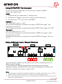
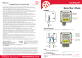
Description
Supplied as a self contained two way Remote Control System which provides two
‘no volt’ switch detect inputs and 6 changeover relay contacts as outputs.
The system comes supplied in an IP56 Enclosure with integral 12V power supply.
Containing industrial standard ‘DIN Rail’ modules.
Ready to Go System 2 I/P,’s 6 O/P’s
110/230VAC
Power
Supply
9-32V
ac or dc
Power
Tx
Rx
Digital
Input 1
Digital
Input 2 Output 1Output 2
2 Input
2
1
6 Output
NO COM NC NO COM NC
Reset 20
30
GSM
10
SIM card
Output 1Output 2Output 3Output 4
Power in
- +
NO COM NC
NO COM NC
NO COM NC
NO COM NC
Address
EZTEXT-DIN 725-OP
4
36
5
2
1
Address
link 1
fitted
PSU
L
E
N
Common
Normally Open
Normally Closed
FUSE
Output 1 -4
Features
• 110-230Vac Power Supply Fused 5A
• 2 No Volt Switch inputs
• 6 Outputs Relay Changeover Contacts
240Vac 5A
• Enclosure IP56
• No PC required.
• SIM Card Bundled
• Dims 315 x 235 x 130mm

EZTEXT-DIN
DS-EZTEXT-DIN-3
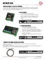
4 x Inputs Module
• 4 x Additional No-Volt Inputs
• Plug ‘n’ Play using ribbon cable supplied
• Up to 4 additional Input Modules can be
Daisy Chained to provide 16 additional
Inputs
• Inputs are opto-isolated
Part Number Description
725-OP 4 Output Add-on Module
4 x Relay Output Module
• 4 x Relay Changeover Contacts
• Connecting ribbon cable supplied
• Up to four Output Modules can be Daisy
Chained to provide an additional 16 Outputs.
• Up to 4 x 725-OP can be Daisy Chained to
provide 18 outputs.
• Provides a simple extension to the number
of Inputs
Part Number Description
725-IP 4 input Add-on Module
Additional Input and Output Modules
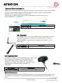
Temperature Measurement Probe Cable
Using the cable adaptor CBA-EZTEMP provides a 1metre plug in cable with
temperature probe.
This enables the EZTEXT temperature monitor temperature and automatically send
notification of high and low user selectable trigger level.
Part Number Description
CBA-EZTEMP2 Temperature sensor cable
The Add-on Modules simply plug into the EZTEXT-DIN Ribbon Connector socket.
Once connected the EZTEXT automatically recognizes them and the additional
inputs and outputs become available to use.

EZTEXT-DIN
DS-EZTEXT-DIN-3
Optional External Antenna
Using an external antenna can provide a better signal reception than the on-board
antenna. Using Cable adaptor CBA-UFLSMA provides a panel mounted SMA
connector for external antenna connection.
To connect, carefully unplug the existing antenna UFL and push on the
CBA-UFLSMA UFL connector.
ANT-GSM5WM
A compact PCB Antenna for GSM Cellular applications where
high performance is required from a small size. Using the
ANT-GSMQB will give optimum range and reliability to your
application.
ANT-GSMPUKS-IP67
A compact Antenna for GSM applications where high
performance is required from a small size. The
antenna includes a Low Noise Amplifier and is
housed in a rugged low profile UV resistant case,
this antenna is compact and resistant to
Vandalism.
CBA-UFLSMA
Connect to
On-board UFL
connector
Alternative Antenna
We offer an extensive range of GSM antenna in many shapes and sizes please see
our Website or contact our Sales Dept with your requirements and we will try to
help.
Part Number Description
CBA-UFLSMA Cable assembly for external antenna
Part Number Description
ANT-GSM5WM +5dBm Gain antenna with wall mount
Part Number Description
ANT-GSMPUK-SMA +3dBm Gain antenna Rugged PUCK

EZTEXT-DIN
DS-EZTEXT-DIN-3
Using EZTEMPR2 Thermocouple
Attach the Thermocouple cable to the Connector marked “SENSE”
This is now ready to use:
Notes:
1. Temperatures are measured to 1 Decimal point
2. Temperature Triggers can be set to whole number values only
3. A hysteresis of –2oC is built into the EZTEXT
Example 1
SET TEMP MAX is set to +30oC
As the actual temperature measured increases, EZTEXT will trigger ‘over
Temperature’ at 30.1oC
As the actual temperature measured decreases EZTEXT will trigger at 27.9oC
Example 2
SET TEMP MIN is set to +10oC
As the actual temperature measured decreases, EZTEXT will trigger ‘under
Temperature’ at 9.9oC
As the actual temperature measured increases EZTEXT will trigger ‘Good’ at
12.1oC
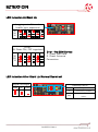
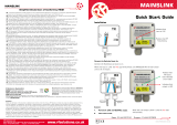
Using Additional Input / Output Modules
Input and Output modules can be added in any order by connecting with the
Ribbon cables supplied.
On initial Powerup EZTEXT automatically interrogates and configures
additional modules. (all LEDS Flash). After approx. 60seconds the LEDs stop
flashing to indicate the module is ready to use
Notes:
1. Any combinations of 725-IP and 725-OP modules can be added, the Maximum is four, 725-IP
Modules and four 725-OP modules in the ‘Daisy Chan’ link (8 modules in total)
2. When using 725-IP / OP modules there are some limitations (compared with the two input and
outputs on the ETEXT-DIN)
Power
Supply
9-32V
ac or dc
Power
Tx
Rx
Digital
Input 1
Digital
Input 2
Relay
Output 1
Relay
Output 2
Power
Input 1 Input 2 Input 3 Input 4
Address Power Power
Input 1 Input 2 Input 3 Input 4
Address Power
3 4 5 6 7 8 910
NO COM NC NO COM NC
Reset 20
30
GSM10
SIM card
EZTEXT-DIN 725-IP 725-IP

EZTEXT-DIN
DS-EZTEXT-DIN-3
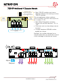
725-OP Additional 4 Outputs Module
Output 1
Ribbon
Cable
Connector
Ribbon
Cable
Connector
Changeover Relay Contact
Outputs
Output 2 Output 3 Output 4
NO COM NCNO COM NC
NO COM NCNO COM NC
Address
ADDRESS LINKS
Place Shorting Cap over
Links to set address
(Fig shows Address position
2)
1
2
3
4
4
Power
Supply
9-32V
ac or dc
Power
Tx
Rx
Digital
Input 1
Digital
Input 2
Relay
Output 1
Relay
Output 2
Input 1 2
2
1
Output
NO COM NC NO COM NC
Reset 20
30
GSM10
SIM card
Output 1 Output 2 Output 3 Output 4 Power in
- +
NO COM NCNO COM NC
NO COM NCNO COM NC
Address
Output 1 Output 2 Output 3 Output 4 Power in
- +
NO COM NCNO COM NC
NO COM NCNO COM NC
Address
3
EZTEXT-DIN 725-OP 725-OP
65 8
710
9
• Each 725-OP module must have a
different address Link setting to other
725-OP modules
(For the application shown address
Link 2 is fitted this sets the outputs to
be numbers 7-10)
• Each Relay Changeover contacts
Output can only be switched “On” or
“Off”.
• Functions such as time delays cannot
be used.
• A single telephone OPNUM number
applies per output
Example: the number allocated to an
output board that you would use to send
a text message to activate an output.

EZTEXT-DIN
DS-EZTEXT-DIN-3
Insert SIM Card
Please note:
• Insert NANO SIM Card before applying power (standard 3 Volt SIM only).
• The message memory of the SIM card should be clear before it is fitted.
• Ensure that the SIM card has not been PIN code protected!
• Beware of Pay-as-you-go SIM which require regular top-up to remain active.
• It is recommended to bar Incoming voice calls to the SIM card to avoid error
messages being sent back to the user. This can be achieved with the service
provider.
The SIM card should be inserted into EZTEXT-DIN before applying power
• RF Solutions recommends O2 and Vodaphone SIM card and has carried out
extensive testing using the SIM cards we have for these two networks.
• No guarantee can be given for the operation of this product with any network
except those that have been tested by RF Solutions.
The EZTEXT-DIN unit can be powered from 12 to 24Vdc
Connect Inputs/Outputs and Power Connections
Supply
Terminals
1 2
Inputs
1 2
Outputs
Module ADDRESS
LINK OUTPUT NUMBERS IPNUM
EZTEXT-DIN INPUT1/Output 1 N/A 1 1
EZTEXT-DIN INPUT2/Output 2 N/A 2 1
725-IP/OP Module Link 1 3-6 2
725-IP/OP Module Link 2 7-10 3
725-IP/OP Module Link 3 11-14 4
725-IP/OP Module Link 4 15-18 5

EZTEXT-DIN
DS-EZTEXT-DIN-3
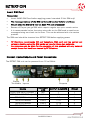
LED Indication At Start Up
Logging onto Network
(traffic light sequence)
30
20
10
Error!
(All Flash ON / OFF together) Error - No GSM Service
1. Check SIM Card
2. Check Antenna
Connection
30
20
10
LED Indication After Start Up (Normal Operation)
Good OK Poor
Signal Strength Activity LED’s
Receiving an SMS RX
TX
GSM
Transmitting an SMS
Intermittent flash GSM
healthy

EZTEXT-DIN
DS-EZTEXT-DIN-3
Good OK Poor
Signal Strength Activity LED’s
Receiving an SMS RX
TX
GSM
Transmitting an SMS
Intermittent flash GSM
healthy
Title
Command
Description
Example
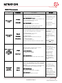
Password
UPW
UPW#UNITPW
User must send UPW command within 5 mins after
power applied. Setting the UPW is carried out by
sending this text message to the unit.
The User Password (4 – 8 Characters) is case sensitive
and can consist of any letters or numbers.
If for any reason the unit password is lost, remove all
power for 1 minute, and then start again.
UPW#1234
(sets password to
1234)
Response:
UPW OK
Unit identity
UID
UNITPW#UID#UNITID
This sets the ‘identity’ of the EZTEXT unit, and will be
included in any response text from EZTEXT.
The UNITID can be 4 to 10 characters with no spaces.
1234#UID#DoorAlarm
Response:
Door Alarm UID OK
Response
RESPONSE
RESPONSE?
UNITPW#RESPONSE#x
Setup a Reply Text EZTEXT after receiving a command
x=ON or OFF
UNITPW#RESPONSE?
Requests the status of the current RESPONSE setting
NOTE: messages which specifically demand a response
such as requests for input status will always be
responded to as will the UPW, UID etc.
Default setting is for response to be turned off.
1234#RESPONSE#ON
Turns on Response
messages
1234#RESPONSE?
Replies with the
EZTEXT setting to
responses
Error Messages & Factory Reset
There are three error messages;
NO AUTHORISATION Means that EZTEXT did not accept the
password
UNRECOGNIZED COMMAND Password correct but the command is
incorrect
UNRECOGNIZED VARIABLE Password and command OK but the
variable data is incorrect
Factory reset:
Hold down the RESET button for approx10 seconds until all LEDs flash, then
release. This will reset EZTEXT to factory default settings and restart.
User Set-Up Commands

EZTEXT-DIN
DS-EZTEXT-DIN-3
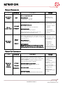
INPUT Commands
Title
Command
Description
Example
Set an input
name
IPNAME
IPNAME?
When the input changes this is the name that the
EZTEXT will transmit in its text message
UNITPW#IPNAMEn#<name>
This designates a <name> to an EZTEXT input
(max15 characters) with no spaces.
n=1 - 2 for inputs1 to 2
UNITPW#IPNAME?
Requests the name given to all inputs
Please note that only the 2 inputs on the main
EZTEXT-DIN module can be given a name.
1234#IPNAME1,Gate
Sets input 1 to be
known as ‘Gate’
1234#IPNAME?
Requests the current
name of input1
Input number
to text
IPNUM
IPNUM?n
IPNUMDEL
Sets the destination phone number(s) (max 5 per
input) when an EZTEXT input is activated.
UNITPW#IPNUMn,<num to text>
n=1 - 2 for inputs1 to 2
UNITPW#IPNUM?n
Requests all Stored cell Nos for that input
UNITPW#IPNUMDELn
n=1 - 2 for inputs1 to 2
Deletes all stored cell Nos for that input number
1234#IPNUM1,00441
234567891
Sets tel No to input 1
1234#IPNUM?1
Requests all stored
telephone numbers for
input 1
1234#IPNUMDEL2
Deletes ALL stored
numbers for input 2
Set number of
input
activations
before SMS
sent
IPCNT
IPCNTVAL?
Sets the number of times an input must be
activated before an SMS is sent
<UNITPW#IPCNTn,x
n= input number (1 or 2)
x= Counter (0 to 65500)
UNITPW#IPCNTVAL?
Requests the actual current value of the counter
1234#IPCNT1,10
A text will be sent after
input 1 has been
activated 10 times
1234#IPCNTVAL?
Responds with ;
INTPUT1= 10/4
intput1 has been
activated 4 times, 6
more activations
required before text
is sent
Delay SMS
on input
activation
IPDLY
IPDLY?
Sets a timer (Max 65500 secs). When the EZTEXT
input is activated the timer starts to countdown in
seconds.
When the counter reaches zero, providing the input
is still activated a text message will be sent.
UNITPW#IPDLYn,xx
n=1 - 2 for inputs1 to 2
‘xx’ can be a number from 0 to 65500
UNITPW#IPDLY?
Requests timer values for all inputs
1234#IPDLY1,60
Input 1 has a 60sec
delay before text is sent
1234#IPDLY?
Responds with ;
INTPUT1= 60/34
(output1 has been ac-
tive for 34 out of a total
60sec preset time.
34secs more is required
before text sent)

EZTEXT-DIN
DS-EZTEXT-DIN-3
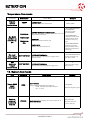
Output Commands
Title
Command
Description
Example
Activate an
output
OUT
Turns an output ON or OFF
UNITPW#OUTn,x
n=Relay number = 1 to 18
x=Relay Status = ON, OFF
1234#OUT1,ON
Turns Output1 ON
Set an
output name
OPNAME
OPNAME?
This designates a name to an EZTEXT output
UNITPW#OPNAMEn,name
n=Output no
name= name can be up to 15 characters.
UNITPW#OPNAME?
Requests the name of the Outputs
Please note that only the 2 outputs on the main
EZTEXT-DIN module can be given a name.
1234#OPNAME1,AIRC
ON
sets output 1 name to
be ‘AIRCON’
1234#OPNAME?
Requests names of all
the outputs
Set output
on time
OPDLY
OPDLY?
Sets output operation time. The output can be set
from 1 to 65500 seconds, or If is set to ‘0’, then the
output will latch on
UNITPW#OPDLYn,t
n=Output number
t=Delay time (seconds)
UNITPW#OPDLY?
Requests the current ‘on’ time setting for an output
EZTEXT replies with the preset time delay output and
the actual time that the output has been activated for
1234#OPDLY1,500
Sets output1 to oper-
ate for 500 sec’s
1234#OPDLY?
Responds with ;
OUTPUT1= 500/34
(output1 has been ac-
tive for 34 out of a total
500sec preset time)
Power Fail Commands
Title
Command
Description
Example
Number to
text on
power
Restored
PFNUM
PFNUM?
PFNUMDEL
Texts will be sent to cell phone numbers stored in
PFNUM on reboot after a power failure or reset (when
power is reapplied).
Note: this feature is enabled or disabled by simply
having cell phone numbers in PFNUM.
UNITPW#PFNUM#<numbertotext>
Sets the number to text on power restored
(Max 5 separate numbers)
UNITPW#PFNUM?
Requests the current numbers that are stored
UNITPW#PFNUMDEL
PFNUMDEL Deletes all stored Power Failed cell Nos
1234#PFNUM#004412
73898000
1234 #PFNUM?
Response: Returns
current settings
1234 #PFNUMDEL
Deletes all stored cell
Nos against this
Example of text:
Building2 Reboot power
had failed

EZTEXT-DIN
DS-EZTEXT-DIN-3
Temperature Commands
Command
Description
Description
Example
Request
current
temperature
TEMP?
UNITPW#TEMP?
requests the current temperature.
1234# TEMP?
Set SMS
numbers to
text on trig-
ger
TEMPNUM
TEMPNUM?
TEMPNUM-
DEL
UNITPW#TEMPNUM#<numbertotext>
Sets the cell phone nos (max of 5) linked with the
temperature monitoring.
TEMPNUM?
Requests all linked cell phone nos
TEMPNUMDEL
Deletes all linked cell phone nos
1234#TEMPNUM#004
41234567891
Sets the number
01234 567891
1234#TEMPNUM?
Requests all cell phone
numbers which will be
notified on temp trig-
gers
1234#TEMPNUMDEL
Deletes all the tele-
phone numbers associ-
ated with Temperature
monitoring
Set maxi-
mum trigger
temperature
SETTEMPMAX
UNITPW#SETTEMPMAX#n
Sets the maximum temperature trigger level in
degrees Celsius.
1234#SETTEMPMAX#3
0
Sets the upper trig-
ger level to 30oC
Set
maximum
trigger
temperature
SETTEMPMIN
UNITPW#SETTEMPMIN#n
Sets the minimum temperature trigger level.
1234#SETTEMPMIN#2
0
Sets the lower trigger
level to 20oC
13. System Commands
Title
Command
Description
Example
Report GSM
signal
strength
SIGQ
UNITPW#SIGQ
Reports EZTEXT GSM signal strength as;
‘POOR’ (consider alternative antenna)
‘OK’, or ‘Good’.
1234#SIGQ
Response: Signal is good
Retrieve
status of
inputs and
outputs
STATUS
UNITPW#STATUS requests the current status of all
inputs and outputs
1234#STATUS
Response: Returns
current settings

EZTEXT-DIN
DS-EZTEXT-DIN-3
Technical Specifications
Storage Temperature: -10 to +70˚C.
Operating Temperature: 0 to +55˚C.
EZTEXT Dimensions: 136 x 78 x 42 mm
*Notes
Figures refer to maximum supply current required with all components idle.
Figures refer to peak supply current required with all components operating.
In practice internal reservoir capacitance limits the instantaneous peak current to less
than 500 mA.
Temperature accuracy
+/- 0.5 degrees between –10 to +80-degree Centigrade
+/- 2.0 degrees between –55 to +110-degree Centigrade
The relay contacts in this unit are for functional switching only and must not be used for
isolation purposes.
Electrical Characteristics* Min Typical Max Dimension Notes
Supply Voltage 12 24 V
Supply Current for EZTEXT:
Idle
Operating
24
200
35
250
45
2A
mA
mA
1
2
Closed Contact Input Time 100 mSecs
Temperature Cable -55 110 oC 3
Mains rated Relay Rating
(230Vac) 5 12 A 4

EZTEXT-DIN
Disclaimer:
Whilst the information in this document is believed to be correct at the time of issue, RF Solutions Ltd does not accept any liability whatsoever for its accuracy, adequa-
cy or completeness. No express or implied warranty or representation is given relating to the information contained in this document. RF Solutions Ltd reserves the
right to make changes and improvements to the product(s) described herein without notice. Buyers and other users should determine for themselves the suitability of
any such information or products for their own particular requirements or specification(s). RF Solutions Ltd shall not be liable for any loss or damage caused as a result
of user’s own determination of how to deploy or use R F Solutions Ltd’s products. Use of RF Solutions Ltd products or components in life support and/or safety applica-
tions is not authorised except with express written approval. No licences are created, implicitly or otherwise, under any of RF Solutions Ltd’s intellectual property rights.
Liability for loss or damage resulting or caused by reliance on the information contained herein or from the use of the product (including liability resulting from negligence
or where RF Solutions Ltd was aware of the possibility of such loss or damage arising) is excluded. This will not operate to limit or restrict RF Solutions Ltd’s liability
for death or personal injury resulting from its negligence.
RF Solutions Ltd. Recycling Notice
Meets the following EC Directives:
DO NOT
Discard with normal waste, please recycle.
ROHS Directive 2011/65/EU as amended by 2015/863/EU
Specifies certain limits for hazardous substances.
WEEE Directive 2012/19/EU
Waste electrical & electronic equipment. This product must be disposed of through a licensed WEEE collection point. RF Solutions Ltd., fulfils its
WEEE obligations by membership of an approved compliance scheme. Environment agency registration agency number: WEE/JB0104WV.
Simplified Declaration of Conformity (RED)
BG -
С настоящото RF Solutions Limited декларира, че този тип радиосъоръжение дефинирани в този документ е в съответствие с Директива 2014/53/ЕС.
Цялостният текст на ЕС декларацията за съответствие може да се намери на следния интернет адрес: www.rfsolutions.co.uk
CS -
Tímto RF Solutions Limited prohlašuje, že typ rádiového zařízení definované v tomto dokumentu je v souladu se směrnicí 2014/53/EU. Úplné
znění EU prohlášení o shodě je k dispozici na této internetové adrese: www.rfsolutions.co.uk
DA -
Hermed erklærer RF Solutions Limited , at radioudstyrstypen defineret i dette dokument er i overensstemmelse med direktiv 2014/53/EU.
EU-overensstemmelseserklæringens fulde tekst kan findes på følgende internetadresse: www.rfsolutions.co.uk
DE -
Hiermit erklärt RF Solutions Limited , dass der Funkanlagentyp in diesem Dokument definiert der Richtlinie 2014/53/EU entspricht. Der
vollständige Text der EU-Konformitätserklärung ist unter der folgenden Internetadresse verfügbar: www.rfsolutions.co.uk
EL -
Με την παρούσα ο/η RF Solutions Limited , δηλώνει ότι ο ραδιοεξοπλισμός ορίζεται σε αυτό το έγγραφο πληροί την οδηγία 2014/53/ΕΕ. Το πλήρες κείμενο
της δήλωσης συμμόρφωσης ΕΕ διατίθεται στην ακόλουθη ιστοσελίδα στο διαδίκτυο: www.rfsolutions.co.uk
EN -
Hereby, RF Solutions Limited declares that the radio equipment type defined within this document is in compliance with Directive 2014/53/
EU. The full text of the EU declaration of conformity is available at the following internet address: www.rfsolutions.co.uk
ES -
Por la presente, RF Solutions Limited declara que el tipo de equipo radioeléctrico definido dentro de este documento es conforme con la
Directiva 2014/53/UE. El texto completo de la declaración UE de conformidad está disponible en la dirección Internet siguiente:
www.rfsolutions.co.uk
ET -
Käesolevaga deklareerib RF Solutions Limited , et käesolev raadioseadme tüüp määratletud selles dokumendis vastab direktiivi 2014/53/EL
nõuetele. ELi vastavusdeklaratsiooni täielik tekst on kättesaadav järgmisel internetiaadressil: www.rfsolutions.co.uk
FI -
RF Solutions Limited vakuuttaa, että radiolaitetyyppi määratletud selles dokumendis on direktiivin 2014/53/EU mukainen. EU-
vaatimustenmukaisuusvakuutuksen täysimittainen teksti on saatavilla seuraavassa internetosoitteessa: www.rfsolutions.co.uk
FR -
Le soussigné, RF Solutions Limited , déclare que l'équipement radioélectrique du type défini dans ce document est conforme à la directive
2014/53/UE. Le texte complet de la déclaration UE de conformité est disponible à l'adresse internet suivante: www.rfsolutions.co.uk
HR -
RF Solutions Limited ovime izjavljuje da je radijska oprema tipa definirani u ovom dokumentu u skladu s Direktivom 2014/53/EU. Cjeloviti tekst
EU izjave o sukladnosti dostupan je na sljedećoj internetskoj adresi: www.rfsolutions.co.uk
HU -
RF Solutions Limited igazolja, hogy a dokumentumban meghatározottak szerint típusú rádióberendezés megfelel a 2014/53/EU irányelvnek.
Az EU-megfelelőségi nyilatkozat teljes szövege elérhető a következő internetes címen: www.rfsolutions.co.uk
IT -
Il fabbricante, RF Solutions Limited , dichiara che il tipo di apparecchiatura radio definito all'interno di questo documento è conforme alla diret-
tiva 2014/53/UE. Il testo completo della dichiarazione di conformità UE è disponibile al seguente indirizzo Internet: www.rfsolutions.co.uk
LT -
Aš, RF Solutions Limited , patvirtinu, kad radijo įrenginių tipas apibrėžta šiame dokumente atitinka Direktyvą 2014/53/ES. Visas ES atitikties
deklaracijos tekstas prieinamas šiuo interneto adresu: www.rfsolutions.co.uk
LV -
Ar šo RF Solutions Limited deklarē, ka radioiekārta kas definēts šajā dokumentā atbilst Direktīvai 2014/53/ES. Pilns ES atbilstības deklarācijas
teksts ir pieejams šādā interneta vietnē: www.rfsolutions.co.uk
MT -
B'dan, RF Solutions Limited , niddikjara li dan it-tip ta' tagħmir tar-radju definit f'dan id-dokument huwa konformi mad-Direttiva 2014/53/UE.
It-test kollu tad-dikjarazzjoni ta' konformità tal-UE huwa disponibbli f'dan l-indirizz tal-Internet li ġej: www.rfsolutions.co.uk
NL -
Hierbij verklaar ik, RF Solutions Limited , dat het type radioapparatuur gedefinieerd in dit document conform is met Richtlijn 2014/53/EU. De
volledige tekst van de EU-conformiteitsverklaring kan worden geraadpleegd op het volgende internetadres: www.rfsolutions.co.uk
PL -
RF Solutions Limited niniejszym oświadcza, że typ urządzenia radiowego zdefiniowane w tym dokumencie jest zgodny z dyrektywą 2014/53/UE.
Pełny tekst deklaracji zgodności UE jest dostępny pod następującym adresem internetowym: www.rfsolutions.co.uk
PT -
O(a) abaixo assinado(a) RF Solutions Limited declara que o presente tipo de equipamento de rádio definido neste documento está em con-
formidade com a Diretiva 2014/53/UE. O texto integral da declaração de conformidade está disponível no seguinte endereço de Internet:
www.rfsolutions.co.uk
RO -
Prin prezenta, RF Solutions Limited declară că tipul de echipamente radio definit în acest document este în conformitate cu Directiva
2014/53/UE. Textul integral al declarației UE de conformitate este disponibil la următoarea adresă internet: www.rfsolutions.co.uk
SK -
RF Solutions Limited týmto vyhlasuje, že rádiové zariadenie typu definované v tomto dokumente je v súlade so smernicou 2014/53/EÚ. Úplné
EÚ vyhlásenie o zhode je k dispozícii na tejto internetovej adrese: www.rfsolutions.co.uk
SL -
RF Solutions Limited potrjuje, da je tip radijske opreme opredeljeno v tem dokumentu skladen z Direktivo 2014/53/EU. Celotno besedilo izjave
EU o skladnosti je na voljo na naslednjem spletnem naslovu: www.rfsolutions.co.uk
SV -
Härmed försäkrar RF Solutions Limited att denna typ av radioutrustning definieras i detta dokument överensstämmer med direktiv 2014/53/
EU. Den fullständiga texten till EU-försäkran om överensstämmelse finns på följande webbadress: www.rfsolutions.co.uk
-
 1
1
-
 2
2
-
 3
3
-
 4
4
-
 5
5
-
 6
6
-
 7
7
-
 8
8
-
 9
9
-
 10
10
-
 11
11
-
 12
12
-
 13
13
-
 14
14
-
 15
15
-
 16
16
-
 17
17
-
 18
18
-
 19
19
-
 20
20


RF SOLUTIONS PRO-EZTEXT26 Manual de utilizare
- Tip
- Manual de utilizare
în alte limbi
- français: RF SOLUTIONS PRO-EZTEXT26 Manuel utilisateur
- English: RF SOLUTIONS PRO-EZTEXT26 User manual
- italiano: RF SOLUTIONS PRO-EZTEXT26 Manuale utente
Lucrări înrudite
-
RF SOLUTIONS SENW-DC-8T1 Manualul utilizatorului
-
RF SOLUTIONS SWITCHLINK-8S1 Manualul utilizatorului
-
 RF SOLUTIONS ESP-07S Manual de utilizare
-
RF SOLUTIONS FERRET-8S1 Manualul utilizatorului
-
 RF SOLUTIONS MAINSLINK-9 Manualul utilizatorului
-
 RF SOLUTIONS Mainslink Manualul utilizatorului
-
 RF SOLUTIONS 006 Signal Strength Multi Meter Manualul proprietarului
-
 RF SOLUTIONS MAINSLINK-PRO Manualul utilizatorului


Alte documente
-
rfsolutions FOBLOQF-4S1 Manualul utilizatorului
-
 RF FOBBER Manualul utilizatorului
-
 rfsolutions SENW-ACPF Manualul utilizatorului
-
RF TRAP-8S1 Manualul utilizatorului
-
rfsolutions RIOT-SYSTEMP-8S5 Manualul utilizatorului
-
Eaton CEAG ZB-S Mounting And Operating Instructions
-
rfsolutions RIOT-RX-8R4 Manualul utilizatorului
-
Yamaha DME32 Manualul proprietarului
-
-
Yamaha V3 Manualul proprietarului

