Megger NIM 1000 Manual de utilizare
- Categorie
- Măsurare, testare
- Tip
- Manual de utilizare

1
NIM 1000
Net Impedance Meter
USER GUIDE
Issue: 04 (06/2016) - EN
Article number: 82941

2

Consultation with Megger
3
Consultation with Megger
The present system manual has been designed as an operating guide and for
reference. It is meant to answer your questions and solve your problems in as fast and
easy a way as possible. Please start with referring to this manual should any trouble
occur.
In doing so, make use of the table of contents and read the relevant paragraph with
great attention. Furthermore, check all terminals and connections of the instruments
involved.
Should any question remain unanswered or should you need the help of an authorized
service station, please contact:
Megger Limited Seba Dynatronic
Mess- und Ortungstechnik GmbH
Archcliffe Road
Kent CT17 9EN
T: +44 1304 502100
F: +44 1304 207342
E: uksales@megger.com
Dr.-Herbert-Iann-Str. 6
D - 96148 Baunach
T: +49 9544 68 – 0
F: +49 9544 22 73
E: team.dach@megger.com
Hagenuk KMT
Kabelmesstechnik GmbH
Megger USA
Röderaue 41
D - 01471 Radeburg / Dresden
T: +49 35208 84 – 0
F: +49 35208 84 249
E: team.dach@megger.com
Valley Forge Corporate Centre
2621 Van Buren Avenue
Norristown, PA 19403 USA
T: +1 610 676 8500
F: +1 610 676 8610
Megger
All rights reserved. No part of this handbook may be copied by photographic or other means unless Megger
have before-hand declared their consent in writing. The content of this handbook is subject to change without
notice. Megger cannot be made liable for technical or printing errors or shortcomings of this handbook.
Megger also disclaims all responsibility for damage resulting directly or indirectly from the delivery, supply, or
use of this matter.

Terms of Warranty
4
Terms of Warranty
Megger accept responsibility for a claim under warranty brought forward by a customer
for a product sold by Megger under the terms stated below.
Megger warrant that at the time of delivery Megger products are free from manufacturing
or material defects which might considerably reduce their value or usability. This
warranty does not apply to faults in the software supplied. During the period of warranty,
Megger agree to repair faulty parts or replace them with new parts or parts as new (with
the same usability and life as new parts) according to their choice.
This warranty does not cover wear parts, lamps, fuses, batteries and accumulators.
Megger reject all further claims under warranty, in particular those from consequential
damage. Each component and product replaced in accordance with this warranty
becomes the property of Megger.
All warranty claims versus Megger are hereby limited to a period of 12 months from the
date of delivery. Each component supplied by Megger within the context of warranty will
also be covered by this warranty for the remaining period of time but for 90 days at
least.
Each measure to remedy a claim under warranty shall exclusively be carried out by
Megger or an authorized service station.
This warranty does not apply to any fault or damage caused by exposing a product to
conditions not in accordance with this specification, by storing, transporting, or using it
improperly, or having it serviced or installed by a workshop not authorized by Megger.
All responsibility is disclaimed for damage due to wear, will of God, or connection to
foreign components.
For damage resulting from a violation of their duty to repair or re-supply items, Megger
can be made liable only in case of severe negligence or intention. Any liability for slight
negligence is disclaimed.
Since some states do not allow the exclusion or limitation of an implied warranty or of
consequential damage, the limitations of liability described above perhaps may not
apply to you.

Contents
5
Contents
Consultation with Megger ............................................................................................... 3
Terms of Warranty ........................................................................................................... 4
Contents ........................................................................................................................... 5
1 Basic Notes ....................................................................................................... 7
2 Technical Description ...................................................................................... 9
2.1 System Description ............................................................................................ 9
2.2 Technical Data ................................................................................................. 11
2.3 Connections, Controls and Display .................................................................. 12
3 Electrical connection ..................................................................................... 13
4 Operation ........................................................................................................ 16
4.1 System Settings ............................................................................................... 18
4.2 Performing Measurements ............................................................................... 19
4.2.1 Network Impedance Measurement .................................................................. 20
4.2.1.1 Prepare Measurement ...................................................................................... 20
4.2.1.2 Performing the Measurement ........................................................................... 22
4.2.1.3 Analysing Measurement Results ...................................................................... 23
4.2.2 Measuring in Fault Mode .................................................................................. 25
4.2.2.1 Preparing Measurement ................................................................................... 25
4.2.2.2 Performing the Measurement ........................................................................... 26
4.2.2.3 Identifying and Locating Faults ........................................................................ 27
4.3 Exporting the Measured Data .......................................................................... 28
5 Maintenance and care .................................................................................... 29
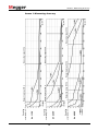
Annex 1: Measuring Accuracy ..................................................................................... 30
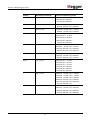
Annex 2: Measuring Range ........................................................................................... 32


Basic Notes
7
1 Basic Notes
This handbook contains basic instructions for the initial use and operation of the NIM
1000. For this reason, it is important to ensure that the manual is always available to
authorised and trained personnel. Operating personnel should read the manual
thoroughly. The manufacturer will not be held liable for any injury or damage to
personnel or property through failure to observe the safety precautions contained in this
handbook.
The specific standards and regulations in each country must also be observed.
Important instructions concerning personnel, operational and technical safety are
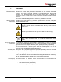
marked in the text as follows:
Symbol Description
WARNING
Indicates a potential danger of an electric shock that may result in fatal or
serious injury.
CAUTION
Indicates a potential danger that may lead to slight or moderate injury.
The notes contain important information and useful tips for using the
system. Failure to observe them can render the measurement results
useless.
It is important to observe the general electrical regulations of the country in which the
device will be installed and operated, as well as the current national accident prevention
regulations and internal company directives (work, operating and safety regulations).
Use genuine accessories to ensure system safety and reliable operation. The use of
other parts is not permitted and invalidates the warranty.
This system and its peripheral equipment may only be operated by trained or instructed
personnel. Anyone else must be kept away.
The system may only be installed by an authorised electrician. DIN VDE 0104 (EN
50191), DIN VDE 0105 (EN 50110) and the German accident prevention regulations
(UVV) define an electrician as someone whose knowledge, experience and familiarity
with the applicable regulations enables him to recognise potential hazards.
The product meets the following security requirements of the European Council
Directives:
• EMC Directive (2004/108/EC)
• Low Voltage Directive (2006/95/EC)
• RoHS Directive (2011/65/EU)
Safety precautions
Labelling of safety
instructions
Working with products
from Megger
Operating staff
Declaration of
Conformity (CE)

Basic Notes
8
The device is intended for operation in the industrial segment in accordance with EN
55011. When used at home it could cause interference with other equipment (such as
the radio or television).
The interference level from the line complies with the limit curve B (living area), the
radiation level complies with the limit curve A (industrial area). Once the living area is
sufficiently far away from the planned area of operation (industrial area), equipment
there will not be impaired.
The operating safety is only guaranteed if the delivered system is used as intended.
Incorrect use may result in danger to the operator, to the system and the connected
equipment.
The thresholds listed in the technical data may not be exceeded under any
circumstances. Condensation during the operation of Megger products may result in
danger to persons and devices through voltage arc-over. Prevent condensation before
and during the measuring mode by cooling the measuring systems sufficiently. The
operation of Megger products in direct contact with water, aggressive substances and
inflammatory gases and vapours is prohibited.
The NIM 1000 is built to be robust and can withstand the stresses it can expect to be
subjected to in demanding everyday use. Nevertheless, it is a precision measuring
device which needs to be treated with the appropriate care. This applies in particular to
the connection cable and the clamps, which play an important role in ensuring the
device remains safe while the results of measurements remain precise.
The system may only be operated whilst it is in perfect working condition. In the event of
damage, irregularities or malfunctions that cannot be resolved with the assistance of the
operating instructions, the system must be shut down immediately and labelled
accordingly. In such an event, the relevant management must be informed. Please
contact Megger Service immediately to eliminate the malfunction. The system may only
be started up again once the malfunction has been eliminated.
Radiated emission
Use only as intended
Procedure in the event
that the device
malfunctions

Technical Description
9
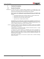
2 Technical Description
2.1 System Description
The NIM 1000 serves to measure network impedance in low voltage grids. In this
process, the conductor connections are tested for their current carrying capacity while
subjected to typical operating loads and potential flaws are indicated.
With the help of the following range of preventative applications, a consistently good
supply quality can be guaranteed, outages prevented and adequate network rating
ensured:
• Preventative inspection and uncovering of faults (e.g. neutral conductor fault)
• Determination of the maximum connected / feed-in power
• Monitoring for secure shut-down (rating of fuses)
• Approval of new / modified network sections
Fault detection in low voltage grids is another area of application of the device. For
example, the NIM 1000 can be used to trigger a load-dependent fault which can then be
located either with the help of a simultaneously connected measuring device or by
means of multiple measurements at various connection points.
The device is linked to the low voltage grid to be tested by means of the available
connection cables (four-conductor measurement with Kelvin clips) and also receives its
supply voltage over these wires.
In preparation for a measurement, either a defined measurement period or a target
number of measurements can be specified.
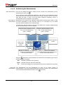
To determine the network impedance, the adjustable load current is generated for a
short period by means of a semi-conductor circuit-breaker with the appropriate load-
resistor. The current and voltage curves are recorded immediately before and while
applying the load by means of A/D converters and then analysed by calculation. The
result is shown on the display.
When taking measurements on more than one phase, there is automatic switching
between the phases.
Intended use
Function

Technical Description
10
The NIM 1000 combines the following features in one device:
• Compact and sturdy design for portable use in the field
• Easy and convenient operation via rotary encoder
• Single and three phase measurement
• High test current of up to 1000 A
• Network impedance measurement (resistance and reactance) up to the
10th harmonic
• Automatic detection of rotary field
• Logging (export via USB interface)
• Wide range input for the voltage supply
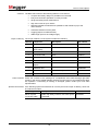
The scope of delivery of the system includes the following:
Quantity Component Description Item number
1 Basic device 128312147
4 High performance
Kelvin clamp
PKC-1 90009319
2 Connection lead brown 90009320
2 Connection lead black 90009321
2 Connection lead grey 90009322
2 Connection lead blue 90009323
1 NIM 1000-A socket
adapter
128311627
1 USB flash drive 890020928
10 Spare fuses T 25A H 440V (6.3 mm x 32 mm) 90004745
1 Manual 82941
Check the contents of the package for completeness and visible damage right after
receipt. In the case of visible damage, the device must under no circumstances be taken
into operation. If something is missing or damaged, please contact your local sales
representative.
If the following optional accessories do not form part of the scope of delivery, these can
be ordered from sales:
Accessory Description Item number
Kelvin clip with
connection cable
Smaller clip ideally suited for use when space
is restricted.
138315892
Features
Scope of delivery
Check contents
Optional accessories

Technical Description
11
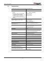
2.2 Technical Data
The NIM 1000 is defined by the following technical parameters:
Parameter Value
Test current
• Range 80 A … 1000 A (adjustable)
• Maximum current as a peak value
(I
max
depends on the network
impedance and the temperature and
is, under certain circumstances,
significantly lower than the indicated
values)
≤1000 A at 400 V
≤600 A at 230 V
≤300 A at 115 V
Input voltage
(supply voltage at the same time)
100 V ... 480 V, 50/60 Hz
(at test terminals)
100 V … 230 V, 50/60 Hz
(at Schuko socket)
Operating uncertainty B (in accordance
with IEC 61557-3)
Up to 3% ±1 mΩ (see also Annex 1)
Measuring range
10 mΩ … 5 Ω (230 V / 400 V)
10 mΩ … 2,5 Ω (115 V)
(See also Annex 2)
Resolution
1 mΩ
Measurement category
300V CAT IV or
600V CAT IV (when using the PKC-1 high
performance connection clamps)
Safety functions
Temperature monitoring
Display
Transflective sunlight readable 5.7" colour
display with a resolution of 640 x 480 pixels
Memory
At least 1000 records of test data
Interfaces
USB 2.0
Operating temperature
-20°C to 55°C
Operating humidity
Max. relative humidity 93% at 30°C
Storage temperature
-30°C to 70°C
Weight
10 kg
Dimensions
410 x 175 x 335 mm
Protection class (in accordance with
IEC 61140 (DIN VDE 0140-1))
II
Ingress protection rating (in accordance
with IEC 60529 (DIN VDE 0470-1))
IP 50 (open)
IP 54 (closed)

Technical Description
12
2.3 Connections, Controls and Display
The NIM 1000 has the following connection, display and control elements:
Element Description
Display
Rotary encoder
USB port
Connection cables
Trigger output

Electrical connection
13
3 Electrical connection
WARNING
Work on live equipment
The work can only be carried out safely while guaranteeing the protection
of the health of all those involved in the work by employing suitable
working procedures and using suitable protective equipment. For that
reason, the electrical connection of the device must absolutely conform to
the nationally applicable regulations for work on live equipment!
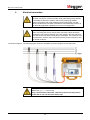
WARNING
Connection sequence
When connecting the device, the two blue connection cables should be
connected to the neutral conductor of the low voltage cable first. Not until
after that can the live phase conductors be connected. The conductors are
disconnected in reverse order: first disconnect the phase conductors, then
the neutral conductor.
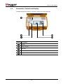
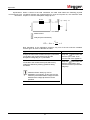
The following figure shows the simplified connection diagram for the NIM 1000:
CAUTION
The fused measurement cables are colour-coded (brown = L1,
black = L2, grey = L3, blue = N).
Only a measurement cable with a matching colourcode may ever be
connected to one and the same Kelvin clip!
Connection diagram

Electrical connection
14
When making electrical connections, the following points should be observed:
• When connected with the supplied PKC-1 high performance connection clamps,
the NIM 1000 is approved for measurements on low voltage installations in the
measurement category 600V CAT IV in accordance with IEC 61010-1.
• The input voltage live on the measurement cables serves simultaneously as
supply voltage and must remain within the range of 100 V and 480 V.
• The NIM 1000 must be connected to the neutral conductor and at least one
phase. If the neutral conductor is not accessible, the blue connection cable must
be connected to a free phase conductor.
• The connection should be made based on the principle of four-conductor
measurement. So two measurement cables (current and voltage) must be
connected to each conductor intended to be measured using a Kelvin clip.
Using the NIM 1000, measurements can be carried out in both single-conductor mode
(just L1–N) as well as in multi-conductor mode (all possible conductor combinations).
Measurements are only carried out on phases which are live with a suitable input
voltage. Accordingly, phases which have not been connected will not be taken into
account in multiple-conductor mode.
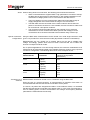
So, for special applications or for time-saving reasons, the conductor combinations to be
measured can be purposefully limited in the multiple-conductor mode by using a specific
connection configuration. The following table shows some examples of this:
Required
measurements
Phases to be
connected
Measured conductor pairs
(instead of the 6 possible
combinations)
L2–N N (blue)
L2 (black)
L2–N
L1–L2 N (blue)
L1 (brown)
L2 (black)
L1–N
L2–N
L1–L2
L2–L3
L2–N
N (blue)
L2 (black)
L3 (grey)
L2–N
L3–N
L2–L3
Measurements can also be carried out on IT networks using the NIM 1000.
Given the lack of a neutral conductor, in measurements on networks of this kind it is
recommended that the blue test lead be connected to a free phase.
If, however, all phases are assigned test leads in multi-conductor mode, it is advisable
that the blue test lead be connected to the station earth or, in the case of an emergency,
even an earthing spike, in order to avoid faults in the voltage- and frequency detection
(otherwise the measurement will not start).
Notes
Specific connection-
configurations
Connection to IT
networks

Electrical connection
15
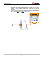
Using the included NIM 1000-A adapter, the NIM 1000 can be quickly and safely
connected to a mains socket for the purposes of measurement or the export of
measurement data. The plug is designed as a Schuko plug (CEE 7/4) but it can also be
connected to sockets of different designs without problem using the appropriate
accessories.
The connection between the NIM 1000 and the adapter should be established as follows
with the help of the blue and the brown connection cables:
Connection to mains
socket

Operation
16
4 Operation
As soon as one of the three connection cables has been connected to a low voltage
phase with sufficient supply voltage (100 V ... 480 V), the NIM 1000 automatically turns
on.
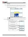
After the short switching on process, the system waits for confirmation from the user that
the electrical connection has been finished.
The corresponding dialogue window can be shut by a quick push of the rotary
encoder , following which the three phase voltages are measured (audible phase
relay switching).
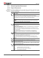
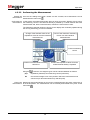
After switching on, the following information on the current status of the system is shown
on the left side of the display:
Power on
System status
Set measuring current
Network voltage and frequency
currently measured
Selected measuring mode (number of
measurements or measurement
duration) and selected operating
mode
Connected phases which are taken
into account in a measurement in
3-conductor mode.

Operation
17
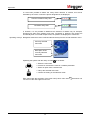
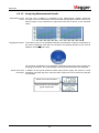
If it has been possible to detect the rotary field’s direction of rotation, this will be
indicated by the colour in which the phase designations are displayed:
If, however, it is not possible to determine the direction of rotation say, for example,
because less than three phases have been connected or because one phase has
accidentally been connected multiple times, the phases are displayed in a black font.
Navigation within the menus is effected almost entirely from the circular selection menu:
Operating the system with the rotary encoder is as follows:
• Select the menu item
• Increase or decrease the value of a variable parameter
• Select an option from a selection list
• Call up the selected menu item
• Confirm the setting or the selection made
Each menu (with the exception of the main menu) has a menu item with which one
can return to the next higher menu level.
Operating concept
Counter-clockwise rotary field
Clockwise rotary field
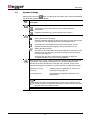
System
Currently selected
menu item
Description of the
currently selected
menu item

Operation
18
4.1 System Settings
Selecting the menu item takes you directly to the system menu, where the following
functions and submenus are available:
Menu
item
Description
Submenu with detailed system information
Information on the current versions of the various software
components
Hardware information (e.g. serial number of the system)
System settings
Setting the interface language.
Select the desired language by turning the rotary encoder and activate
by pressing it. The language selection is immediately active.
In this submenu, the brightness and layout of the display can be
adjusted and the background lighting can be switched on or off.
Setting the date and time.
The value of each segment that has been marked for selection can be
adjusted by turning the rotary encoder. Pressing causes the mark to
move the next segment.
Once the input has been concluded, the changes can either be
accepted with OK or rejected by selecting Cancel.
When this function is used, a search in respect of firmware and language files
is conducted in the directory nig/updates/ on the inserted USB flash drive.
The files found are then listed and, using the rotary encoder, these can be
selected and imported. A distinction is made between the following file types:
application-x.xx.img
Updating solely an application to version x.xx
nig-xxx.tar
Importing the language xxx
nig-Languages.tar
Importing all the languages contained in the
language file
An also possible update of the real-time software of the measuring
hardware needs not be initiated via this menu item. Instead of this, it
suffices to insert the USB flash drive with the update files into the USB
port and confirm the following query.

Operation
19
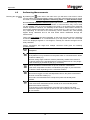
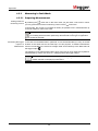
4.2 Performing Measurements
By selecting the menu item in the main menu you will reach a sub menu in which
you may select your desired operating mode. In principle, measurements may be carried
out either in normal network impedance measuring mode or in fault detection mode.
Normal network impedance measuring takes place with a constant measuring current
and over a freely-adjustable duration or number of measurements. Only in this mode
can the software carry out a load calculation (see page 7) on the basis of the measured
network impedance. However, the suitability of this mode to detect faults is limited, as
some faults subside temporarily with higher current flows (e.g. due to fusing or drying
out). Depending on the level of the measuring current selected, this could already
happen during calibration and so the fault would remain undetected through the
measurement.
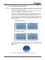
That is why fault mode has been integrated. In this mode, the load current is gradually
increased over the course of 8 measurements up to the preset value. All 8 recorded
curves are displayed together in one diagram, whereby the relevant changes can be
easily identified.
Further sub-division into single and multiple conductor mode gives the following
operating modes:
Menu
item
Description
Network impedance measurement on one conductor
The impedance is only measured on the phase which is connected via the brown
connection cables (L1).
This time-saving single-conductor mode is particularly suitable if the results of
one phase suffice for the intended purpose of the measurement or if only single-
phase measuring is possible anyway (e.g. at sockets).
Network impedance measurement on up to 6 conductor combinations
In this mode, all possible conductor combinations (see page 14) are measured
one after the other depending on the connection situation.
Fault mode on one conductor
This serves to trigger a known load-dependent fault on the phase connected to
the brown connection cables (L1).
This mode is recommended if the conspicuous phase has already been
identified.
Fault mode on up to three conductors
In this mode the 8 measurements are carried out on all connected phases
(against the neutral conductor).
So conclusions on the characteristic of the fault can be drawn from load-
dependent impedance changes as well as from the comparison of the phases
with one another.
Selecting the operating
mode

Operation
20
4.2.1 Network Impedance Measurement
4.2.1.1 Prepare Measurement
By selecting the menu item in the main menu you will reach a sub menu in which
you may select the following measurement parameters in preparation for a network
impedance measurement.
Menu
item
Description
Maximum measuring current (80 ... 1000 A)
Because the accuracy of the measurement increases with increasing
measuring current, as high as possible a measuring current but also one which
is appropriate to the capacity of the network should be selected.
If the NIM 1000 is connected to a mains socket (with fusing of up to
16 A), the 80 A setting which has been particularly dimensioned for
this type of application should be selected!
Total measurement duration (0 … 20 days) and interval of the individual
measurements.
Over the whole measurement duration, one measurement per involved phase
is taken at the set interval.
After the menu item is selected, the two values are to be defined one after
another. The options for setting the interval depend on the previously set total
measurement time.
The number of measurements can also be defined as an alternative to
measurement duration (see below). The respective last adopted setting
applies.
Number of measurements (1 … 255)
The set number of measurements is carried out in quick succession and while
constantly switching between the phases involved.
The measurement duration can also be defined as an alternative to the
number of measurements (see above). The respective last adopted setting
applies.
Delay time (0 … 30 seconds)
The start of the measurement can be delayed by the time set here.
Resetting calibration values
If the time of calibration was quite a while ago (e.g. after a measurement which
lasted a while or in the case of temporary failure of a phase), it could be useful
to reset the calibration values.
Value to be calculated using a load calculation (see information on next page
too)
V
DIP
Voltage dip at given connection power
P
MAX
Max. connection power at given voltage dip
Off
Load calculation deactivated
Setting the
measurement
parameters
Pagina se încarcă...
Pagina se încarcă...
Pagina se încarcă...
Pagina se încarcă...
Pagina se încarcă...
Pagina se încarcă...
Pagina se încarcă...
Pagina se încarcă...
Pagina se încarcă...
Pagina se încarcă...
Pagina se încarcă...
Pagina se încarcă...
Pagina se încarcă...
-
 1
1
-
 2
2
-
 3
3
-
 4
4
-
 5
5
-
 6
6
-
 7
7
-
 8
8
-
 9
9
-
 10
10
-
 11
11
-
 12
12
-
 13
13
-
 14
14
-
 15
15
-
 16
16
-
 17
17
-
 18
18
-
 19
19
-
 20
20
-
 21
21
-
 22
22
-
 23
23
-
 24
24
-
 25
25
-
 26
26
-
 27
27
-
 28
28
-
 29
29
-
 30
30
-
 31
31
-
 32
32
-
 33
33


Megger NIM 1000 Manual de utilizare
- Categorie
- Măsurare, testare
- Tip
- Manual de utilizare
în alte limbi
- English: Megger NIM 1000 User manual