Tetra MAX 24V Colors LED Signage Ghid de instalare
- Tip
- Ghid de instalare

MAX
LED Lighting System
Installation Guide
SIGN208 | GE2032-1428
GEMX24RD-W1, GEMXH24RD-W1, GEMX24GL-W1,
GEMX24BL-W1, GEMX24YG-W1
RETROFIT SIGN CONVERSION LED KIT FOR USE ONLY IN
ACCORDANCE WITH KIT INSTRUCTIONS.
KIT IS COMPLETE ONLY WHEN ALL PARTS REQUIRED BY
THE INSTRUCTIONS ARE PRESENT.
TROUSSE DE CONVERSION À DEL POUR LA
MODERNISATION DES ENSEIGNES
À UTILISER CONFORMÉMENT AU GUIDE D’INSTALLATION.
Save These Instructions
Use only in the manner intended by the manufacturer. If
you have any questions, contact the manufacturer.
For the latest North American install guides for your product go to: https://products.LED.com/led-signage-lighting
For the latest European install guides for your product go to: https://products.LED.com/eu
FOR UL ONLY
BG Българската версия на инструкциите за инсталаця и
информация за безопасност могат да бъдат намерени
на следния адрес: https://products.LED.com/eu
CS Návod k montáží a bezpečnostní informace v češtině
najdete zde: https://products.LED.com/eu
DA Den danske version af installationsvejledningen og
sikkerhedsoplysninger kan findes på følgende placering:
https://products.LED.com/eu
DE Die deutsche Version der Installationsanleitung und
Sicherheitsinformationen finden Sie in folgendem Verzeic:
https://products.LED.com/eu
EL Μπορείτε να βρείτε την ελληνική εκδχή των οδηγιών
νγκατάστασης και των πληροφοριών ασφάλειας στην
εξής τοποθεσία: https://products.LED.com/eu
ES La versión española de las instrucciones de instalación y
la información sobre seguridad puede encontrarse en la
siguiente ubicación: https://products.LED.com/eu
ET Eestikeelse paigaldusjuhendi ja ohutusnñuded leiate
aadressilt: https://products.LED.com/eu
FI Asennusohjeiden ja turvallisuustietojen suomenkielinen
versio löytyy seuraavasta paikasta: https://products.LED.
com/eu
FR La version française des instructions d’installations
et information de sécurité est disponible à l’adresse
suivante: https://products.LED.com/eu
HR Hrvatska verzija priručnika za ugradnju i sigurnosnih
informacija nalazi se na sljedečoj lokaciji: https://products.
LED.com/eu
HU A telepítési útmutató és a biztnosági információk magyar
nyelvű változata az alábbi címen található: https://
products.LED.com/eu
IT La versione italiana del manuale di installazione e
sicurezza può essere reperita nella seguente sezione:
https://products.LED.com/eu
LT Lietuvišką diegimo instrukcijos ir saugos informacijos
versiją galima rasti šioje vietoje: https://products.LED.
com/eu
LV Uzstādīšanas instrukciju un drošības informāciju latviešu
valodā var atrast šeit: https://products.LED.com/eu
NL De Nederlandse versie van de installatie-instructies en
veiligheidsinformatie kan op de volgende locatie worden
gevonden: https://products.LED.com/eu
PL Polską wersję instrukcji instalacji oraz informacje
dotyczące bezpieczeństwa można znaleźć w następującej
lokalizacji: https://products.LED.com/eu
PT A versão em Português das instruções de instalação e
das informações de segurança pode ser encontrada na
seguinte localização: https://products.LED.com/eu
RO Versiunea în limba română a instrucţiunilor de instalare
şi a informaţiilor de siguranţă pot fi găsite la: https://
products.LED.com/eu
SV Ni hittar den svenska versionen av
installationsanvisningarna och säkerhetsinformationen på
följande plats: https://products.LED.com/eu
SL Previdnostna opozorila in varnostne informacije so na
zadnji strani vodnika za namestitev. Pred začetkom
namestitve izdelka jih skrbno preberite: https://products.
LED.com/eu
SK Slovenskú verziu montažnej príručky a bezpečnostnŷch
instrukcií nájdete na nasledujúcej lokalite: https://
products.LED.com/eu
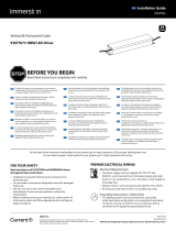
BEFORE YOU BEGIN
Read these instructions completely and carefully.
2424
Volt
Prepare Electrical Wiring
Electrical Requirements
• Acceptable for use in dry, damp and wet locations.
• The grounding and bonding of the LED Driver shall be
done in accordance with National Electric Code (NEC)
Article 600.
• Follow all National Electric Codes (NEC) and local codes.
• These products are only suitable for connection to a
circuit from a Class 2 power source.
• These products have not been evaluated for use when
connected to a power source that does not comply with
Class 2 voltage and energy limited supplies.
EN

Tetra® MAX Installation Guide
2
TC Measure Point
WARNING / AVERTISSEMENT
RISK OF ELECTRIC SHOCK
∙ Turn power off before inspection, installation or removal.
∙ Properly ground power supply enclosure.
RISK OF FIRE
∙ Use only suitably approved wire for input/output
connections. Minimum size 18 AWG (0.82mm2)
∙ Follow all local codes.
∙ Not to be submerged or used in a marine environment.
RISQUES DE DÉCHARGES ÉLECTRIQUES
∙ Coupez l’alimentation avant l’inspection, l’installation ou le déplacement.
∙ Assurez-vous de correctement mettre à terre l’alimentation électrique.
RISQUES D’INCENDIE
∙ N’utilisez que des fils approuvés par UL pour les entrées/sorties de connexion. Taille
minimum 18 AWG (0.82mm2)
∙ Respectez tous les codes locaux.
∙ Ne pas submerger ou installer dans un environnement marin.
UL WARNING / AVERTISSEMENT UL
RISK OF FIRE OR ELECTRIC SHOCK
∙ LED Retrofit Kit installation requires knowledge of
sign electrical systems. If not qualified, do not attempt
installation. Contact a qualified electrician.
∙ Install this kit only in host signs that have been identified in
the installation instructions and where the input rating of the
retrofit kit does not exceed the input rating of the sign.
∙ Installation of this LED retrofit kit may involve drilling or
punching of holes into the structure of the sign. Check for
enclosed wiring and components to avoid damage to wiring
and electrical parts.
∙ Do not make or alter any open holes in an enclosure of
wiring or electrical components during kit installation.
RISQUE D’INCENDIE OU DE CHOC ÉLECTRIQUE
∙ L’installation de l’équipement de remplacement DEL exige Ia connaissance des
systèmes électriques pour enseignes. Si non qualifié, ne tentez pas d’installation.
Veuillez contacter un électricien qualifié.
∙ Risque d’incendie ou de choc électrique. Installez cet ensemble seulement dans des
enseignes hôtes qui ont été identifiés dans les instructions d’installation et dont la
capacité d’entrée de l’ensemble ne dépasse pas la capacité d’entrée de l’enseigne.
∙ L’installation de cet équipement de remplacement DEL peut impliquer le perçage
ou le poinçonnage de trous dans la structure du panneau Vérifiez le câblage et
les composants inclus pour éviter d’endommager le câblage et les composants
électriques.
∙ Ne pas faire ou modifier les trous ouverts dans une enceinte de câblage
ou de composants électriques pendant l’installation de cet équipement de
remplacement DEL.
This device complies with part 15 of the FCC Rules. Operation is subject to the following two conditions: (1) This device may not cause harmful
interference, and (2) this device must accept any interference received, including interference that may cause undesired operation.
NOTE: This equipment has been tested and found to comply with the limits for a Class A digital device, pursuant to part 15 of the FCC Rules. These limits
are designed to provide reasonable protection against harmful interference when the equipment is operated in a commercial environment. This equipment
generates, uses, and can radiate radio frequency energy and, if not installed and used in accordance with the instruction manual, may cause harmful
interference to radio communications. Operation of this equipment in a residential area is likely to cause harmful interference in which case the user will be
required to correct the interference at his own expense.
This Class [A] RFLD complies with the Canadian standard ICES-005. Ce DEFR de la classe [A] est conforme à la NMB-005 du Canada.
1
12
2
3
3
4
4
5
5
6
67
7
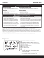
Components
UL approved 18 AWG (0.82 mm2) supply wire
UL approved 22-14 AWG (0.33-2.08 mm2) wire connectors or
22-18 AWG (0.33-0.82 mm2) in-line/IDC connectors
#6 (M3) screws, 1/8 inch (3.2 mm) rivets, or electrical grade RTV
silicone or equivalent
Weather box GEXNWB2 (optional)
24 Volt Power Supply
Tetra® MAX LED modules
Electrical grade RTV silicone:
• Momentive RTV 6700 Series Silicone Rubber Adhesive Sealant
• Momentive White Blanc RTV 162 Silicone Rubber Adhesive
Sealant-Electrical Grade
• Dow Corning 3140 - Non-Corrosive Flowable (clear)
• Dow Corning 3145 - Non-Corrosive Nonflowable (clear or gray)
• Dow Corning RTV 748 Non-Corrosive Sealant-White

Tetra® MAX Installation Guide
3
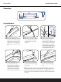
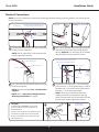
Measure and cut Tetra LED
strip to the appropriate length
for each letter. Cuts can be
made between any of the
modules.
Use rivets, screws, or
electrical grade RTV silicone
to secure at least every
fifth LED module within the
channel letter. Use #6 (M3)
pan headed metal screws,
1/8-inch (3.2 mm) rivets, or
electrical grade RTV silicone.
Drill a 1/4-inch (6.4 mm)
hole near the LED strip and
grommet the hole for supply
wire access.
Remove all the debris from
the inside of the channel
letter and replace the sign
face.
NOTE: For halo-lit applications LED modules should be mounted on
UL recognized clear acrylic or polycarbonate. The light output from
the LED system should be directed back into the sign enclosure. This
will allow for uniform backlighting of the sign and will provide simple
mounting.
Before you begin, clean
surfaces and remove all debris
from the inside of the channel
letter.Clean the surfaces with
a 50:50 mixture of isopropyl
alcohol (IPA) and water and let
dry.
Layout Modules
Dimensions
Remove tape backing and
stick LED modules into place.
When using tape apply
approximately 15 psi pressure
on the module (avoid the lens
dome surface) for 5 seconds,
full bonding strength after 24
hours. Continue until you have
reached the end of the strip.
Do not
press lens
[3.45]
87.60
[.45]
11.41
[.63]
16.10
2
5
1
4
3
6

Tetra® MAX Installation Guide
4
Electrical Connections
NOTE: Do not use connectors pre-filled with silicone grease/mineral base protective grease or use silicone grease
to seal connections.
To LED
power
supply
Red (+)
Black or blue (-)
Red Stripe (+)
Cap wires Optional: Cut wires flush
Connect LED strips using in-line (IDC) connectors
or twist-on wire connectors.
NOTE: Seal all connections in wet locations with
electrical grade RTV silicone.
Must cap all exposed wires with appropriate wire
connectors and seal with electrical grade RTV
silicone. Optional: Cut wires flush to the module
and seal with electrical grade RTV silicone.
Run a wire from the LED power supply to the LED
module and connect.
NOTE: Must be used with Class 2 24 Volt Power
Supplies.
NOTE: Refer to Maximum Loading & Remote
Mounting Specications on page 5.
Connect the red stripe wire (+) of the LED strip
to the red wire (+) of the power supply. Connect
the white wire (-) of the LED strip to the black or
blue wire (-) of the LED power supply.
NOTE: All electrical connections should be
suitably protected from mechanical damage
and the environment. Seal all connections in wet
locations with electrical grade RTV silicone.
LED
Power
Supply
To Tetra LED System
Red (+)
Black or blue (-)
Red stripe (+)
White (-)
White (-)
Seal all connections in wet locations
with electrical grade RTV silicone
Seal all connections in wet locations
with electrical grade RTV silicone
OPTIONAL
A Weather Box (GEXNWB2) may be used
to house and seal Class 2 connections as
described below:
A) Insert wire connectors into weather box. Fill
with electrical grade silicone and close box.
B) Secure the weather box using a #6 or #8
(M2 or M3) screw.
Weather box
can be painted
Light engine
A B
2
1
3 4

Tetra® MAX Installation Guide
5
Tips
• For optimal light uniformity in halo-lit applications the Tetra® LED modules should be mounted on UL recognized plastic and the light
output from the Tetra® LED system should be directed back into the sign enclosure. This will allow for uniform backlighting of the sign
and will provide simple mounting for the Tetra® LED system.
• A best practice for the supply wire at the point at which it is brought into the sign is to have a drip loop on the inside of the letter to
keep water from collecting on the Tetra® LED strip.
• These products are not required to be enclosed or protected from weather.
Troubleshooting
Symptom Solution
All letters are OFF • Check AC input connection and/or check circuit breaker.
• Check wire connection(s) at the Tetra® LED System and power supply for improper termination(s) or short
circuits. Properly terminate or replace the wire connection(s).
• Check that connections are the red striped wire (+) of the LED strip to the red wire (+) of the power supply
and the white wire (-) of the LED strip to the black or blue wire (-) of the power supply.
Some LEDs
appear dim
• Ensure the overall length of the Tetra® LED System does not exceed the maximum load.
• Ensure the length of supply wire is equal to or below the recommended remote mounting distance.
• Ensure the overall length of the Tetra® LED System does not exceed the maximum load.
Some of the letters
are not illuminated
• Check wire connection(s) at the Tetra® LED System and power supply for improper termination(s) or short
circuits. Properly terminate or replace the wire connection(s).
• Check that connections are the red striped wire (+) of the LED strip to the red wire (+) of the power
supply and the white wire (-) of the LED strip to the black or blue wire (-) of the power supply.
Shadows • Re-route supply wire and secure to the back of the can with electrical grade RTV silicone. Adjust wire
connector orientation so that it does not cover any LEDs.
• Adjust LED layout to ensure uniformity of illumination on the face of the letter.
1. (Existing Signs Only) Prior to installation, survey the site for information regarding power and accessibility inside and outside the building. Ensure
that the branch circuit supplying the existing transformer or ballast will be within the voltage ratings of the new LED power supply, and have a current
rating not exceeding 20A, or that permitted by applicable local, state, or country electrical codes (whichever is less).
2. (Existing Signs Only) Remove the existing lighting equipment to be replaced, such as neon tubing or fluorescent tubes; and associated
transformers and ballasts. Care should be taken not to break the existing neon or fluorescent tubes. NOTE: Follow all federal and local regulations
when disposing of neon tubing, fluorescent tubes, transformers and ballasts.
3. (Existing Signs Only) If removal of the existing lighting equipment eliminates the disconnect switch, as required by applicable local, state, or
country electrical codes; a new disconnect switch must be installed.
4. (Existing Signs Only) Repair and seal any unused openings in the electrical enclosure. Openings greater than 12.7-mm (1/2-in) diameter require a
metal patch secured by screws or rivets and caulked with non-hardening caulk. Smaller openings may be sealed with non-hardening caulk.
5. (Existing Signs Only) A clean and dry mounting surface ensures optimum adhesion if the self-adhesive method of mounting is chosen. Follow
the manufacturer’s directions when using a non-oil based solvent, such as rubbing alcohol to clean the surface area where you intend to mount the
module. Before installing, ensure the surface is dry.
6. Using the layout guidelines above, determine required number of LED modules required to illuminate the sign.
7. A 24VDC Class 2 Power Supply, as listed below, must be used with this retrofit kit. Using the Maximum Loading chart below, determine the number of
Power Supplies required to power the number of LED modules required to illuminate the sign, so as not to overload the Power Supply chosen.
8. Follow the instructions above to properly mount the LED modules.
9. Connect the DC output of the power supply to the LED modules using the Electrical Connections instructions above.
10. Connect the power unit to the supply in accordance with the applicable local, state, and country electrical codes, and the instructions found in the
power supply installation guide.
11. If required, the disconnect switch shall be installed by qualified personnel, in accordance with applicable local, state, and country electrical codes.
FOR UL ONLY
Retrofit Instructions

Tetra® MAX Installation Guide
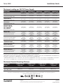
NOTE: The maximum loading claimed in the table is at ambient temperature 25°C (77°F).
For linear long runs, center connection to the LED strip is recommended to minimize voltage drop.
*GELP24-60U-GL minimum load = 44 modules / 29 ft. (8.94 m) for GEMX24RD-W1, 27 modules / 18 ft. (5.59 m) for GEMXH24RD-W1 and GEMX24GL-W1,
29 modules / 19 ft. (5.90 m) for GEMX24BL-W1, or 53 modules / 35 ft. (10.77 m) for GEMX24YG-W1.
**GEPS24V50-100W minimum load = 110 modules / 74 ft. (22.56 m) for GEMX24RD-W1, 68 modules / 46 ft. (14.02 m) for GEMXH24RD-W1, 66 modules
/ 44 ft. (13.41 m) for GEMX24GL-W1, 72 modules / 48 ft. (14.63 m) for GEMX24BL-W1, or 131 modules / 88 ft. (26.82 m) for GEMX24YG-W1.
Maximum Loading per 24V DC Power Supply
Power Supply GEMX24RD-W1 GEMXH24RD-W1 GEMX24GL-W1 GEMX24BL-W1 GEMX24YG-W1
Rating per module 24VDC
19mA/module
0.456W/module
24VDC
31mA/module
0.744W/module
24VDC
32mA/module
0.768W/module
24VDC
29mA/module
0.696W/module
24VDC
16mA/module
0.384W/module
GEPS24-25U-NA
Load shall not exceed 1.04A
47 modules/
31.3 ft. (9.55 m) 29 modules/
19.3 ft. (5.89 m) 28 modules/
18.7 ft. (5.69 m) 31 modules/
20.7 ft. (6.3 m) 56 modules/
37.3 ft. (11.38 m)
GEPS24D-60U-GLX
*GELP24-60U-GL
Load shall not exceed 2.5A
120 modules/
80 ft. (17.88 m) 73 modules/
48 ft. (14.83 m) 71 modules/
47 ft. (14.42 m) 78 modules/
52 ft. (15.84 m) 143 modules/
95 ft. (29.05 m)
GEPS24D-80U
GEPS24W-80
Load shall not exceed 3.3A
150 modules/
100 ft. (30.48 m) 92 modules/
61.3 ft. (18.69 m) 89 modules/
59.3 ft. (18.08 m) 98 modules/
65.3 ft. (19.91 m) 180 modules/
120 ft. (36.58 m)
GEPS24-100U-GLX
GEPS24D-100U-NA
GEPS24LT-100U-NA
USVI-100024FBA
USVI-100024FE
Load shall not exceed 4.0A
180 modules/
120 ft. (36.58 m) 110 modules/
73.3 ft. (22.35 m) 107 modules/
71.3 ft. (21.74 m) 118 modules/
78.6 ft. (23.98 m) 210 modules/
140 ft. (42.67 m)
GEPS24-180U
Load shall not exceed 3.8A per
each (of 2) output channels
168 modules/
112 ft. (34.14 m)
per bank
336 modules/
224 ft. (68.27 m)
per PS
103 modules/
68.7 ft. (20.93 m)
per bank
206 modules/
137.3 ft. (41.86 m)
per PS
100 modules/
66.7 ft. (20.32 m)
per bank
200 modules/
133.3 ft. (40.64 m)
per PS
110 modules/
73.3 ft. (22.35 m)
per bank
220 modules/
146.7 ft. (44.7 m)
per PS
200 modules/
133.3 ft. (40.64 m)
per bank
400 modules/
266.7 ft. (81.28 m)
per PS
GEPS24-300U-GL
Load shall not exceed 4.0A per
each (of 3) output channels
180 modules/
120 ft. (36.58 m)
per bank
540 modules/
360 ft. (109.7 m)
per PS
110 modules/
73.3 ft. (22.35 m)
per bank
330 modules/
220 ft. (67 m)
per PS
107 modules/
71.3 ft. (21.74 m)
per bank
321 modules/
214 ft. (65.23 m)
per PS
118 modules/
78.6 ft. (23.98 m)
per bank
354 modules/
236 ft. (71.93 m)
per PS
210 modules/
140 ft. (42.67 m)
per bank
630 modules/
420 ft. (128 m)
per PS
GEPS24-100U-GLX2/TT
**GEPS24V50-100W
Load shall not exceed 4.0A
190 modules/
126.6 ft. (38.58 m) 116 modules/
77.3 ft. (23.5 m) 113 modules/
75.3 ft. (22.9 m) 124 modules/
82.6 ft. (25.1 m) 226 modules/
150.6 ft. (45.9 m)
GEPS24-200U-GLX2
Load shall not exceed 4.0A per
each (of 2) output channels
190 modules/
126.6 ft. (38.5 m)
per bank
380 modules/
253.2 ft. (77.2 m)
per PS
116 modules/
77.3 ft. (23.5 m)
per bank
232 modules/
154.6 ft. (47.1 m)
per PS
113 modules/
75.3 ft. (22.9 m)
per bank
226 modules/
150.6 ft. (45.9 m)
per PS
124 modules/
82.6 ft. (25.1 m)
per bank
248 modules/
165.2 ft. (50.3 m)
per PS
226 modules/
150.6 ft. (45.9 m)
per bank
452 modules/
301.2 ft. (91.8 m)
per PS
GEPS24-300U-GLX2
Load shall not exceed 4.0A per
each (of 3) output channels
190 modules/
126.6 ft. (38.5 m)
per bank
570 modules/
379.8 ft. (155.8 m)
per PS
116 modules/
77.3 ft. (23.5 m)
per bank
348 modules/
231.9 ft. (70.7 m)
per PS
113 modules/
75.3 ft. (22.9 m)
per bank
339 modules/
225.9 ft. (68.8 m)
per PS
124 modules/
82.6 ft. (25.1 m)
per bank
372 modules/
247.8 ft. (75.5 m)
per PS
226 modules/
150.6 ft. (45.9 m)
per bank
678 modules/
451.8 ft. (137.7 m)
per PS
This product is intended solely for the use of non-residential signage lighting and is not intended for use in any other applications.
Conforms to the following standards: IP66 rated
III
Power Supply
Wattage
18 AWG/0.82 mm2
Supply Wire
16 AWG/1.31 mm2
Supply Wire
14 AWG/2.08 mm2
Supply Wire
12 AWG/3.31 mm2
Supply Wire
25W 120 ft./36.6 m – – –
60W, 80W, 100W,
180W, 200W, 300W 20 ft./6.1 m 25 ft./7.6 m 35 ft./10.6 m 40 ft./12.1 m
Maximum Remote Mounting Distance
LED.com
© 2023 Current Lighting Solutions, LLC. All rights reserved. Information and specifications subject to change
without notice. All values are design or typical values when measured under laboratory conditions.
Page 6 of 6
(Rev 06/19/23)
SIGN208 | GE2032-1428
-
 1
1
-
 2
2
-
 3
3
-
 4
4
-
 5
5
-
 6
6


Tetra MAX 24V Colors LED Signage Ghid de instalare
- Tip
- Ghid de instalare
în alte limbi
Lucrări conexe
-
Tetra Ti-10 24V GEPS24-100U-TT Signage Power Supply Ghid de instalare
-
-
Tetra GEPS24-100U-TT Ghid de instalare
-
-
-
-
-
-
-
Alte documente
-
GE current SIGN287 Manual de utilizare
-
 Immersion GELP24-100U-GLX Power Supply Ghid de instalare
-
Eaton CEAG DualGuard-S Mounting And Operating Instructions
-
-
Mellanox Technologies Switch-IB Manual de utilizare
-
Yamaha PM4000 Manual de utilizare
-
-
-
Current IND227 Ghid de instalare
