Sames ISOCUBE pour Nanogun Airmix H2O Manual de utilizare
- Categorie
- Pulverizator de vopsea
- Tip
- Manual de utilizare

Index revision : B - September 2019 1 7120
User manual
SAMES KREMLIN SAS - 13, Chemin de Malacher - 38240 MEYLAN - FRANCE
Tel. 33 (0)4 76 41 60 60 - www.sames-kremlin.com
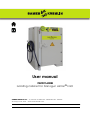
ISOCUBE
Isolating cabinet for Nanogun Airmix® H2O

Index revision : B - September 2019 2 7120
This document may not be disclosed or copied, in any form, and its content may not be used
or disclosed, without the explicit written authorisation of SAMES KREMLIN.
The descriptions and characteristics contained in this document may be modified without prior
notice.
© SAMES KREMLIN 2017
WARNING : SAMES KREMLIN SAS has been declared as a training centre with the
Ministry of employment.
Our company organises training courses providing the indispensable know-how
for the installation and maintenance of our equipment all year long.
A catalogue is available on request. Select the training programme, type of
learning method and skills you need from our range, to meet your production
targets.
These training courses can be organised on the premises of your company or at
the training centre located at our head office in Meylan.
Training service:
Tel.: 33 (0)4 76 41 60 04
E-mail: formation-clie[email protected]
The symbol means Warning important point.
SAMES KREMLIN SAS has drafted this operating manual in French and mandated English, German, Spanish, Italian
and Portuguese translations.
The company declares reservations on all translations and refuses any liability with respect to these translated
documents.

Index revision : 3
ISOCUBE
Isolating cabinet for Nanogun Airmix® H2O
1. Health and safety guidelines - - - - - - - - - - - - - - - - - - - - - - - - - - - - 5
1.1. Marking . . . . . . . . . . . . . . . . . . . . . . . . . . . . . . . . . . . . . . . . . . 5
1.2. Simplified analysis of potential sources of electric shocks . 5
1.3. Precautions during use . . . . . . . . . . . . . . . . . . . . . . . . . . . . . . 6
1.4. Warnings . . . . . . . . . . . . . . . . . . . . . . . . . . . . . . . . . . . . . . . . . . 6
1.5. Installation rules . . . . . . . . . . . . . . . . . . . . . . . . . . . . . . . . . . . . 7
1.6. Rules of use . . . . . . . . . . . . . . . . . . . . . . . . . . . . . . . . . . . . . . . 7
1.7. Maintenance rules . . . . . . . . . . . . . . . . . . . . . . . . . . . . . . . . . 8
2. Description - - - - - - - - - - - - - - - - - - - - - - - - - - - - - - - - - - - - - - - - - - 9
2.1. Overview front face . . . . . . . . . . . . . . . . . . . . . . . . . . . . . . . 10
3. Characteristics - - - - - - - - - - - - - - - - - - - - - - - - - - - - - - - - - - - - - - 11
3.1. Characteristics of the compressed air . . . . . . . . . . . . . . . . 12
4. Use - - - - - - - - - - - - - - - - - - - - - - - - - - - - - - - - - - - - - - - - - - - - - - - 13
4.1. Transport and Handling . . . . . . . . . . . . . . . . . . . . . . . . . . . . 13
4.2. Installation . . . . . . . . . . . . . . . . . . . . . . . . . . . . . . . . . . . . . . . 14
4.3. Connection of the Nanogun Airmix® H2O spray gun . . . . 15
4.4. Installing the product regulator (option) . . . . . . . . . . . . . . 16
4.5. Installation of the stirrer (option) . . . . . . . . . . . . . . . . . . . . . 17
4.6. Start-up . . . . . . . . . . . . . . . . . . . . . . . . . . . . . . . . . . . . . . . . . . 18
4.6.1. Placement of the paint drum . . . . . . . . . . . . . . . . . . . . . . . . . 18
4.6.2. Priming the pump . . . . . . . . . . . . . . . . . . . . . . . . . . . . . . . . . . . 18
4.6.3. Ventilation . . . . . . . . . . . . . . . . . . . . . . . . . . . . . . . . . . . . . . . . . 19
4.7. Settings and operating modes . . . . . . . . . . . . . . . . . . . . . . 20
4.8. Standard stop . . . . . . . . . . . . . . . . . . . . . . . . . . . . . . . . . . . . 21
4.9. Work on the inside of the isolating cabinet . . . . . . . . . . . . 21
4.10. Emergency stop . . . . . . . . . . . . . . . . . . . . . . . . . . . . . . . . . 21
4.11. Complete shutdown of the installation . . . . . . . . . . . . . . 21
5. Cleaning - - - - - - - - - - - - - - - - - - - - - - - - - - - - - - - - - - - - - - - - - - - 22
5.1. Ongoing maintenance . . . . . . . . . . . . . . . . . . . . . . . . . . . . 22
5.1.1. Nanogun Airmix® H2O spray gun and hoses. . . . . . . . . . . . . 22
5.1.2. Insulating cabinet . . . . . . . . . . . . . . . . . . . . . . . . . . . . . . . . . . . 22
5.1.3. Electro-pneumatic headband . . . . . . . . . . . . . . . . . . . . . . . . 23
6. Maintenance - - - - - - - - - - - - - - - - - - - - - - - - - - - - - - - - - - - - - - - 24
6.1. Maintenance table . . . . . . . . . . . . . . . . . . . . . . . . . . . . . . . 24
6.2. Short circuiter 60kV . . . . . . . . . . . . . . . . . . . . . . . . . . . . . . . . 24
6.2.1. Preventive maintenance . . . . . . . . . . . . . . . . . . . . . . . . . . . . . 24
6.2.3. Corrective maintenance.. . . . . . . . . . . . . . . . . . . . . . . . . . . . . 26
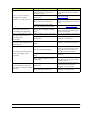
7. Common malfunctions and repairs - - - - - - - - - - - - - - - - - - - - - - 31
8. Spare parts - - - - - - - - - - - - - - - - - - - - - - - - - - - - - - - - - - - - - - - - - 33
8.1.
ISOCUBE for Nanogun Airmix
®
H
2
O spray gun 120 bar version
33

Index revision : 4
8.1.1. 120 bar version, Europe . . . . . . . . . . . . . . . . . . . . . . . . . . . . . . 34
8.1.2. 120 bar version, US-CSA . . . . . . . . . . . . . . . . . . . . . . . . . . . . . . 36
8.2.
ISOCUBE for Nanogun Airmix
®
H
2
O spray gun 200 bar version
38
8.2.1. 200 bar version, Europe . . . . . . . . . . . . . . . . . . . . . . . . . . . . . . 39
8.2.2. 200 bar version, US-CSA . . . . . . . . . . . . . . . . . . . . . . . . . . . . . . 40
8.3. ISOCUBE cabinet equipped . . . . . . . . . . . . . . . . . . . . . . . . 41
8.3.1. Discharge resistor. . . . . . . . . . . . . . . . . . . . . . . . . . . . . . . . . . . . 43
8.3.2. Short circuiter 60kV . . . . . . . . . . . . . . . . . . . . . . . . . . . . . . . . . . 44
8.4. The pump units . . . . . . . . . . . . . . . . . . . . . . . . . . . . . . . . . . . 45
8.4.1. Pump kit, 120 bar version . . . . . . . . . . . . . . . . . . . . . . . . . . . . . 45
8.4.2. FLOWMAX Pump kit, 120 bar version. . . . . . . . . . . . . . . . . . . . 47
8.4.3. Pump kit, 200 bar version . . . . . . . . . . . . . . . . . . . . . . . . . . . . . 49
8.4.4. FLOWMAX pump kit, 200 bar version . . . . . . . . . . . . . . . . . . . 51
8.5. Product pressure regulator (option) . . . . . . . . . . . . . . . . . . 53
8.6. Fitted stirrer (option) . . . . . . . . . . . . . . . . . . . . . . . . . . . . . . . 54

Index revision : B - September 2019 5 7120
1. Health and safety guidelines
This document contains links to the following operation manuals:
•see RT Nr 7118 for the Nanogun Airmix® H2O spray gun
•See user manual ref: 578 050 120 for the 120 and 200 bar pumps
•See user manual ref: 582 017 110 705 for the 120 bar FLOWMAX pump
•See user manual ref: 582 018 110 705 for the 200 bar FLOWMAX pump
•See user manual ref: 578 001 130 1103 for the product filter
•See user manual ref: 573 008 211 for the product pressure regulator (option)
•See user manual ref: 573 303 050 for the stirrer (option).
1.1. Marking
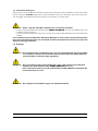
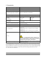
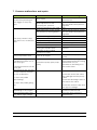
1.2. Simplified analysis of potential sources of electric shocks
With the use of non-flammable products (as defined in the standard EN 50059-2018 Annex C),
the risk of ignition is by definition nil or low, but on the other hand, these products contain large
quantities of water which quickly store quantities of energy sufficient to cause electric shocks
that would exceed the limits as defined in the standard EN 50059-2018 Annexes A and B.
That is why the ISOCUBE insulating cabinet is equipped with systems to prevent this type of risk.
Potential source of elec-
tric shock Measures Means applied
Voluntary or involuntary
contact with the pump or
the paint drum
Automatic earthing of all parts
under HV if the door is opened
Time to implementation of
security measures of less
than 2 sec
Voluntary or involuntary
contact with the gun
injector
Limitation of the length of the
product pipe to 15 m max and
the capacity of the product
drum to maximum 20 l.
20 l max for all the contain-
ers which must be con-
ductors and connected to
the equipotential connec-
tion (supplied)
Resistance against permanent
discharge
Prohibition of spraying of prod-
ucts with a resistivity below
1000 Ω.cm.
Incorrect earthing
The equipment must be earthed
by means of at least 2 points: its
electrical supply and a dedi-
cated wire (supplied)
The operator must periodi-
cally check the quality of
the earthing outlets
DES06842
Registered Design
3
U output : 60 kV I output : 80µA IP20
Admissible combinations of devises, see informations for use
Maximum conductivity of the coating product 1000 µS/cm

Index revision : B - September 2019 6 7120
1.3. Precautions during use
All operators must familiarise themselves with and understand the information in this document
before using the ISOCUBE equipment. This information points out situations that can cause seri-
ous damage and indicates the precautions to be taken to avoid them.
WARNING : Before using the ISOCUBE equipment, be sure that all operators:
• have received preliminary training from SAMES KREMLIN, or from the distributors it has
certified for this purpose.
• have read and understood the user’s manual as well as all installation and use rules listed
below.
It is incumbent upon the Operators’ Workshop Manager to ensure and verify that all operators
have read and understood the user’s manuals relative to peripheral electrical devices present
within the spraying perimeter.
1.4. Warnings
WARNING : This equipment may be hazardous if it is not used, disassembled and reassembled
in accordance with the rules indicated in this manual and in any applicable Euro-
pean Standard or national safety regulations.
WARNING : The good working order of this equipment is only under warranty provided that
original spare parts distributed by SAMES KREMLIN are used.
Only components and accessories distributed by SAMES KREMLIN contained in this
user manual may be used.
WARNING : This equipment is intended to spray non flammable liquids.

Index revision : B - September 2019 7 7120
1.5. Installation rules
•The ISOCUBE isolating cabinet has been designed to operate within a 2nd-degree pollu-
tion environment, as defined according to the Standards IEC 60664-1and IEC 61010-
1:2010.
2nd-degree pollution: Under normal use conditions, only non-conductive type pollution
arises. On a temporary basis, conduction caused by condensation may arise.
•The ISOCUBE isolating cabinet must be installed indoors, outside installation is strictly pro-
hibited.
• The ISOCUBE insulating cabinet must be installed outside the coating area.
• The hand-held electrostatic projection equipment can only be used in designated pro-
jection spots in accordance with Standard EN 16985 or under equivalent ventilation con-
ditions.
• This equipment must not be used in a cab or an application room for solvent-based paints,
flammable liquids or ones which form explosive atmospheres.
• The use of this equipment in a work area for the application of electrostatic flammable
products or ones which form explosive atmospheres is dangerous.
• The ISOCUBE consists of the projection spray gun, the control module, the hose, the pump
and the product tank, which must be considered as a whole. Any technical change can
increase the stored electric energy in the whole set to a dangerous degree. It is strictly for-
bidden to modify the equipment.
• Install the isolating cabinet away from any explosive zone.
• Servo-control the isolating cabinet to the “on” position of the booth’s suction fan.
• Correctly connect the control module to the installation’s ground terminal.
• Connect the pump and the product tank by means of an equipotential connection that
is provided.
• The container of the spray product must be electrically conductive (metal) and con-
nected to the circuit by the crocodile claw.
• Connect all metal parts of the installation (paint pumps, containers, stools, spin coaters,
etc., which positioned within three meters of the spray gun to the ground.
• Keep the spray zone clean and free of all unnecessary components.
• The floor where the operator works must be antistatic (either unclad concrete flooring or
a metal grating). Never cover the floor with an insulating covering. In potentially explosive
locations, the floor assemblies must be antistatic, in accordance with Standard EN 61340-
4-1.
• The use inside the booth of an uncovered flame, any incandescent object, a device or
object capable of generating sparks other than the gun is strictly prohibited.
It is also prohibited to store in the vicinity of the booth or in front of the doors flammable
products or containers in which such products had been stored.
• The jars and cans containing paint or solvent must be systematically closed after use.
• The supply pump of the paint used must have a maximum ratio of 18:1 for the Nanogun
Airmix® H2O 120 bar and 34:1 for the Nanogun Airmix® H2O 200 bar. The pump’s air inflow
must be equipped with a safety relief valve (supplied) to limit pressure to a maximum
value of 6.5 bar.
•Inside an explosive zone, it is prohibited to use electrical or non-electrical equipment that
has not been certified, like electrical extension cables, surge protector power bars,
switches, etc.
1.6. Rules of use
• Verify the extraction ventilation system efficiency on a daily basis.
• Once a week, verify the adequate operations of the ventilation system servo controls.
• Correctly ground all metal parts of the booth, along with the parts to be painted. The
resistance relative to the ground must be less than or equal to 1MΩ (for a 500-V voltage
measurement). This resistance must be regularly checked and, in any case, at least once
a week.

Index revision : B - September 2019 8 7120
• Ensure that anyone entering the spray zone is wearing the antistatic shoes in accordance
with Standard EN 61340-4-3. The measured insulation resistance must not exceed 100MΩ.
• The protective clothing intended to be worn, including gloves, must be compliant with
Standard EN 1149-5. The measured insulation resistance must not exceed 100MΩ.
• The operator must also wear ear defenders when using the spray guns
Nanogun Airmix® H2O.
• The operator must hold the Nanogun Airmix® H2O either with a bare hand or with anti-
static gloves or gloves modified so as to establish a direct contact between the butt and
his/her hand.
• The device can only be operated if it is in perfect condition. Any damaged equipment
must be immediately removed from active service and repaired.
Worn parts must be immediately replaced.
• Closely follow use guidelines for the paints and solvents being applied (e.g. wear a mask).
• Close and dump both the air and paint inlet prior to any extended equipment downtime.
• Before any cleaning or maintenance operation, discharge the equipment to earth (the
discharge is done automatically if the door is open).
• Verify the good working order of the paint hose prior to any equipment start-up.
1.7. Maintenance rules
• Regularly maintain and repair the electrostatic projection equipment according to the
instructions contained in this user’s manual.
• Only use metal containers to hold the cleaning liquids and connect to ground according
to a safe procedure.
• Before any maintenance procedure:
1 Turn off the control module.
2 Dump the paint circuit.
3 Verify that the air and paint circuits are no longer pressurised.
4 All energy sources must be locked out.
• Clean the equipment either in their dedicated spots with mechanical ventilation or by
using cleaning liquids with a flash point at least 15°C higher than ambient temperature.
• Use non-flammable cleaning products.
WARNING : It is strictly prohibited to use solvents derived from halogenated hydrocarbons as
well as products containing these solvents in the presence of aluminium or zinc. Failure to
comply with these guidelines exposes the user to the risks of explosion.

Index revision : B - September 2019 9 7120
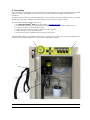
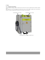
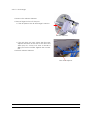
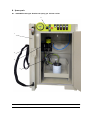
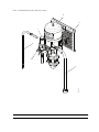
2. Description
This equipment is designed for the application of water-based or water-thinnable hydrosoluble
paint or varnish. The liquids sprayed must be non-flammable and highly conductive to
electricity.
To apply paints of this type electrostatically, the most simple and most effective way is to place
the liquid under high voltage, and electrically isolate the paint supply system.
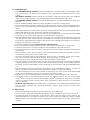
The ISOCUBE isolating cabinet consists of:
•of a Nanogun Airmix® H2O spray gun (Item1) (see RT Nr 7118),
• an electropneumatic box (Item 2) including the GNM 6080 control module (Item 3),
•A pump unit (Item 4) supplying the gun,
• A 60kV short circuiter located on the top of the cabinet,
• a stirrer (Item 5) as an optional extra.
• a product pressure regulator (not shown) as an option.
The ISOCUBE cabinet is equipped with safety systems that protect the operator against elec-
trical shocks, by blocking access to the parts under high voltage.
1
2
5
4
3

Index revision : B - September 2019 10 7120
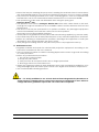
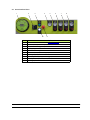
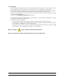
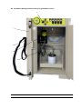
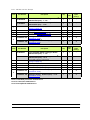
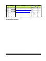
2.1. Overview front face
Item Description
1GNM 6080 control module (see RT Nr 7118)
2Main switch (lockable)
3On / off button (green)
4Air supply pressure
5Pressure flow regulator
6Pressure pump power supply
7Stirring supply pressure
8 Spraying air supply pressure (gun)
9Emergency stop
10 Voltage presence white LED indicator
1234 678
9
5
10

Index revision : B - September 2019 11 7120
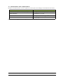
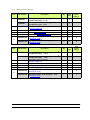
3. Characteristics
(*) - The measurement of the viscosity of a water-soluble paint using a consistometric cup leads
to very significant errors. In effect, these paints are thixotropic: their viscosity decreases with the
intensity of agitation and with the time for which they are stirred. At rest, these paints are highly
viscous substances; in contrast, in movement, they become not very viscous substances. The
viscosities shown are indicative for paint stirred just before being measured with a cup.
(**) - Any other use is prohibited
Footprint (W x H x P) 1100 x 1640 x 650
Mass 170 Kg
Maximum operating altitude 2,000 m
Min/max ambient temperature 5°C - 40°C
Maximum relative humidity of 80% for
temperatures of up to 31°C, then linear
decrease until 50% relative humidity at
40°C
Maximum of 80% without condensation
Operating voltage 60 kV maximum (adjustable on GNM 6080)
Maximum current 80 µA max.
Electrical power supply:
- Voltage
- Frequency
- Consumption
Europe version
230 V ± 10%
50 -60 Hz
200 VA
CSA Version
110V± 10%
50 -60 Hz
200 VA
Overvoltage Overvoltage category II according to Standard IEC
61010-1:2010
Maximum compressed air pressure 7 bar ± 0,5 bar (101 psi ± 7,25) (exhaust valve cali-
brated at 6,5/7 bar)
Max. air flow Approximately 40 Nm3/h.
Product viscosity Between 20 mPas/s and 250 mPas/s approximately
Max. product flow
According to the viscosity and the thixotropy of the
product (*):
- Approx. 700 cc/min. for a liquid at 30 s by weight
AFNOR no. 4:
- Approx. 250 cc/min. for a liquid at 90 s by weight
AFNOR no. 4:
Products
Non flammable paints with a minimum resistivity that
must be between 1KΩ.cm and maximum 250 kΩ.cm.
(**).
WARNING : Not appropriate and also dangerous for
the solvent-based paints, resistive liquids and flamma-
ble liquids that form explosive atmospheres.
Filtration of the coating product Provided by a filter-strainer (200 μm) which is easily dis-
mantled and cleaned.

Index revision : B - September 2019 12 7120
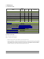
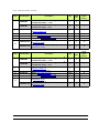
3.1. Characteristics of the compressed air
Required characteristics of the compressed air supply according to Standard NF ISO 8573-1
(*): The values are given for a temperature of 20°C (68°F) at atmospheric pressure.
Characteristics Value
Maximum dew point at 6 bar (87 psi) Category 4, i.e. +3°C (37° F)
Maximum particle size distribution of the
solid pollutants Category 3 i.e. 5 mm
Maximum oil concentration Category 1, i.e. 0.01mg / m03 *
Maximum concentration of solid pollutants 5 mg / m03 *

Index revision : B - September 2019 13 7120
4. Use
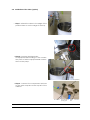
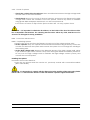
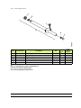
4.1. Transport and Handling
The ISOCUBE insulating cabinet is delivered in a box that can be handled with a forklift or pallet
truck.
The cabinet out of its packaging is handled by means of the forklift or pallet truck, but also by
means of straps through the four holes on the sides of the cabinet.
Positioning of the strap
Positioning of the forklift or pallet truck
Positioning of the strap

Index revision : B - September 2019 14 7120
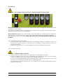
4.2. Installation
• The ISOCUBE isolating cabinet must be installed and used outside of any explosive area.
• The emergency stop must be free of access in order to facilitate any operation.
•Ensure the correct earth connection of the parts to be painted (open electrical connec-
tion of the electrical earthfeeder, cleanliness of the metal suspension hooks).
• Be sure to maintain this good connection the whole time. Ensure that the suspension hooks
are frequently stripped.
•Connect the Nanogun Airmix® H2O spray gun.
• The elements of the ISOCUBE (electro-pneumatic box, pump, pressure regulation, security
systems) are delivered connected.
• Connections of the cabinet:
• Connect the earth of the cabinet using the earth wire fitted with a terminal.
• Connect the compressed air inlet hose (customer supplied) (3/8" BSP female, Ø 8 inte-
rior, length 10 m maximum) to the supply valve.
• Connect the AC power cord to the electrically adapted network (the supply voltage
is indicated on the nameplate located on the cabinet).
Nota: The symbol means "Caution: Electrical shock hazard".
Note: The tray can be handled with a lifting device such as a forklift truck.

Index revision : B - September 2019 15 7120
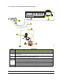
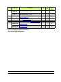
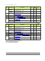
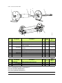
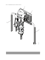
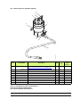
4.3. Connection of the Nanogun Airmix® H2O spray gun
Item Description
1Nanogun Airmix® H2O spray gun
2Spray air (quick coupler to connect on TR 3)
3Low-voltage cable (screw-on connector on the female connector of the
GNM 6080)
4Product hose passing through the cable gland, to connect to the pump
(Ref.: 910020516-075), maximum length: 15 m
5GNM 6080
6
Pump version 120 bar (maximum pressure. 97.5 bar - 1414 psi)
Pump version 200 bar (maximum pressure. 195 bar - 2827 psi)
Pump FLOWMAX version 120 bar (maximum pressure. 100 bar - 1450 psi)
Pump FLOWMAX version 200 bar (maximum pressure. 200 bar - 2900 psi)
7Paint drum (max. capacity. 20l - 5,28 US gal)
4
5
1
2
3
6
7
DES06841
TR 7
TR 6 TR 3 TR 5 TR 4
TR 2
TR 3
TR 1

Index revision : B - September 2019 16 7120
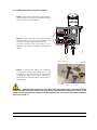
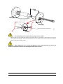
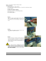
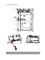
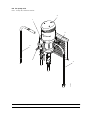
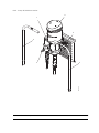
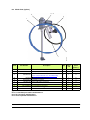
4.4. Installing the product regulator (option)
•Step 1: Attach the regulator at the bottom
and to the left of the perforated plate using
the bolts and nuts provided.
•Step 2: Screw one side of the phosphorus
green product hose to the filter outlet and
the other to the regulator inlet (fitting
1/2 JIC), and the hose of the gun is con-
nected to the elbow fitting at the regulator
outlet.
•Step 3: Connect one side of the regulator
control hose using a tube diam 4 ext . (not
supplied) to the quick bleed of the regula-
tor and the other to the 4 mm quick cou-
pler located on the inside at the top left of
the cabinet.
WARNING : After fitting the regulator kit to the grid to the side of the pump, check the electrical
continuity between the point that connects all the equipotential bonding (black wire on the
pump or on the grid) and the metal part of the regulator, the value measured with a multimeter
must not exceed 1 Ω.
DES06854
Stirrer connec-
tion
Air supply for
gun
HV cable
Ventilation
Product regulator

Index revision : B - September 2019 17 7120
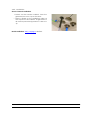
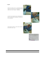
4.5. Installation of the stirrer (option)
•Step 1: Attach the stirrer to the edge of the
product drum or on the edge of the tray.
•Step 2: Connect the black wire
for equipotential bonding to the connec-
tion point of all the equipotential connec-
tions on the pump.
•Step 3: Connect the compressed air hose
to the quick coupler on the top left of the
cabinet.
Stirrer connec-
tion
Air supply for
spray gun
HV cable
Ventilation

Index revision : B - September 2019 18 7120
4.6. Start-up
WARNING : The complete start-up is done by "double clicking" the green button.
The first press triggers the compressed air supply for the pump, the regulator (if present) and the
ventilation of the cabinet.
This makes it possible fill, flush and/or bleed the product circuit quickly, and this action is func-
tional even if the door is open or unlocked.
The second press triggers the power supply to the GNM 6080, the compressed air required for
the spray gun, for the stirrer if it is present, for the short circuiter and its ventilation, and the
ISOCUBE is then ready to operate. If the door is left open or not locked, this second press has
no effect.
4.6.1. Placement of the paint drum
• Place the paint drum on the receptacle in the isolating cabinet, covered in its cover. It is
important to put the cover on to avoid the hose coming out under the effect of the pres-
sure of the product.
• Make sure that there is no product dripping onto the receptacle for the drum.
4.6.2. Priming the pump
WARNING : To start the pump, you must:
• Open the door in order to allow the equipment to discharge to the earth.
• Pour the vaseline oil into the cup (= cylindrical part in which the piston rod is located),
except FLOWMAX type pumps which do not require lubrication.
• If there are priming difficulties (pasty coating product), start the priming with water to fill
the hoses, then replace the water with the coating product.
• It is important, for the life of the pump, not to allow it to run unprimed(operating at more
than 30 cycles/min).

Index revision : B - September 2019 19 7120
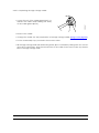
4.6.3. Ventilation
Check internal ventilation:
• Switch on the Isocube cabinet. Press the
green button once. Open the door.
•Place a finger on the ventilation outlet at
the top left of the cabinet. A light blast of
air must be perceived (pressure 0.1 bar +0.1
-0).
Booth ventilation: see § 1.5 page 7 alinéa 3.
Ventilation

Index revision : B - September 2019 20 7120
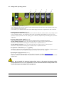
4.7. Settings and operating modes
•Compressed air pressure (Item 1):
The equipment has an air exhaust valve which bleeds the air from the network if the pres-
sure is greater than 6.5/7 bar.
In this case, you will hear the noise of air bleeding: lower the air pressure in the network.
•Product pressure regulator (Item 2):
The regulator product is virtually never used in the 200 bar version and is very rarely used
in the 120 bar version. This setting is also easily accessible depending on the stop. The
product supply pressure at the spray gun is directly adjusted by actuating this pressure
regulator.
•Pressure pump power supply(Item 3):
The supply pressure of the pump must be adjusted in the following manner
For the 120 bar versions: From 0 to 6.5 bar based on the product to be sprayed
Pressure of the product coming out of the pump = air pressure x 15
For the 200 bar versions: From 0 to 6.5 bar based on the product to be sprayed
Pressure of the product coming out of the pump = air pressure x 30.
•Air pressure on the stirrer (Item 4) (option) :
Between 2 and 4 bar depending on the viscosity of the product, and the rotation speed
of the propeller must be adjusted using the needle valve on the engine.
•Spraying air supply pressure(Item 5):
From 1.4 to 6 bar depending on the product's viscosity and flow (see RT Nr 7118).
Beyond 4 bar, the de-solvation of the product and the production of mists can increase
significantly.
WARNING : Do not modify the pressure setting of the valve, as the proper functioning of the
pump depends on it. It is very important to use de-oiled and drained compressed air to
ensure the proper functioning of the equipment.
12 34 5
Pagina se încarcă...
Pagina se încarcă...
Pagina se încarcă...
Pagina se încarcă...
Pagina se încarcă...
Pagina se încarcă...
Pagina se încarcă...
Pagina se încarcă...
Pagina se încarcă...
Pagina se încarcă...
Pagina se încarcă...
Pagina se încarcă...
Pagina se încarcă...
Pagina se încarcă...
Pagina se încarcă...
Pagina se încarcă...
Pagina se încarcă...
Pagina se încarcă...
Pagina se încarcă...
Pagina se încarcă...
Pagina se încarcă...
Pagina se încarcă...
Pagina se încarcă...
Pagina se încarcă...
Pagina se încarcă...
Pagina se încarcă...
Pagina se încarcă...
Pagina se încarcă...
Pagina se încarcă...
Pagina se încarcă...
Pagina se încarcă...
Pagina se încarcă...
Pagina se încarcă...
Pagina se încarcă...
Pagina se încarcă...
-
 1
1
-
 2
2
-
 3
3
-
 4
4
-
 5
5
-
 6
6
-
 7
7
-
 8
8
-
 9
9
-
 10
10
-
 11
11
-
 12
12
-
 13
13
-
 14
14
-
 15
15
-
 16
16
-
 17
17
-
 18
18
-
 19
19
-
 20
20
-
 21
21
-
 22
22
-
 23
23
-
 24
24
-
 25
25
-
 26
26
-
 27
27
-
 28
28
-
 29
29
-
 30
30
-
 31
31
-
 32
32
-
 33
33
-
 34
34
-
 35
35
-
 36
36
-
 37
37
-
 38
38
-
 39
39
-
 40
40
-
 41
41
-
 42
42
-
 43
43
-
 44
44
-
 45
45
-
 46
46
-
 47
47
-
 48
48
-
 49
49
-
 50
50
-
 51
51
-
 52
52
-
 53
53
-
 54
54
-
 55
55


Sames ISOCUBE pour Nanogun Airmix H2O Manual de utilizare
- Categorie
- Pulverizator de vopsea
- Tip
- Manual de utilizare
în alte limbi
Lucrări înrudite
-
Sames electrostatic gun KM.3 H2O Manual de utilizare
-
-
-
-
-
-
-
-
-


