Makita DGP180 Ghid de instalare

Tip
Ghid de instalare
DGP180
EN Cordless Grease Gun INSTRUCTION MANUAL 7
PL Smarownica Akumulatorowa INSTRUKCJA OBSŁUGI 15
HU Akkumulátoros zsírzópisztoly HASZNÁLATI KÉZIKÖNYV 23
SK Akumulátorová mazacia
pištoľ NÁVOD NA OBSLUHU 31
CS Akumulátorový mazací lis NÁVOD K OBSLUZE 39
UK Акумуляторний шприц для
мастила ІНСТРУКЦІЯ З
ЕКСПЛУАТАЦІЇ 47
RO Pistol de gresat cu
acumulator MANUAL DE INSTRUCŢIUNI 56
DE Akku-Fettpresse BETRIEBSANLEITUNG 64
11
1
2
13
14
12
16
17
2
5
5
3
4
15
6
8
9
10
7
Fig.1
2
1
3
Fig.2
1
2
Fig.3
BA
1
12
3
Fig.4
2
1
Fig.5
2
1
Fig.6
1
Fig.7
1
Fig.8
1
Fig.9
12
Fig.10
1
2
Fig.11
12
1
2
Fig.12
3
1
2
3
Fig.13
1
2
Fig.14
Fig.15
Fig.16
1
Fig.17
Fig.18
1
3
2
Fig.19
5
1
2
3
4
Fig.20
4
Fig.21
1
Fig.22
Fig.23
Fig.24
Fig.25
1
2
Fig.26
1
34
5
2
Fig.27
1
3
2
Fig.28
5
1
2
Fig.29
Fig.30
1
2
Fig.31
1
Fig.32
Fig.33
1
2
Fig.34
1
Fig.35
6
7ENGLISH
ENGLISH (Original instructions)
SPECIFICATIONS
Model: DGP180
Rated voltage D.C. 18 V
Grease capacity
(with A-type barrel) Cartridge 410 g
Bulk 455 g
Grease capacity
(with B-type barrel) Cartridge 450 g
Bulk 570 g
Maximum operating pressure 69 MPa
Maximum ow rate Slow speed mode 145 ml/min
Auto speed mode 290 ml/min
Applicable grease type NLGI No.0 - No.2
Hose length 1,200 mm
Overall length With A-type barrel 411 mm
With B-type barrel 449 mm
Net weight 4.8 - 6.1 kg
NOTE: The barrel type (A-type or B-type) varies depending on the country.
Due to our continuing program of research and development, the specications herein are subject to change
without notice.
Specications and battery cartridge may dier from country to country.
The weight may dier depending on the attachment(s), including the battery cartridge. The lightest and heavi-
est combinations, according to EPTA-Procedure 01/2014, are shown in the table.
Applicable battery cartridge and charger
Battery cartridge BL1815N / BL1820B / BL1830B / BL1840B / BL1850B / BL1860B
Charger DC18RC / DC18RD / DC18RE / DC18SD / DC18SE / DC18SF /
DC18SH
Some of the battery cartridges and chargers listed above may not be available depending on your region of
residence.
WARNING: Only use the battery cartridges and chargers listed above. Use of any other battery cartridges
and chargers may cause injury and/or re.
Intended use
This tool is intended for dispensing grease.
Noise
The typical A-weighted noise level determined accord-
ing to EN62841-1:
Sound pressure level (LpA) : 76 dB(A)
Uncertainty (K) : 3 dB(A)
NOTE: The declared noise emission value(s) has
been measured in accordance with a standard test
method and may be used for comparing one tool with
another.
NOTE: The declared noise emission value(s)
may also be used in a preliminary assessment of
exposure.
WARNING: Wear ear protection.
WARNING: The noise emission during actual
use of the power tool can dier from the declared
value(s) depending on the ways in which the
tool is used especially what kind of workpiece is
processed.
WARNING: Be sure to identify safety mea-
sures to protect the operator that are based on an
estimation of exposure in the actual conditions of
use (taking account of all parts of the operating
cycle such as the times when the tool is switched
o and when it is running idle in addition to the
trigger time).
8ENGLISH
Vibration
The vibration total value (tri-axial vector sum) deter-
mined according to EN62841-1:
Vibration emission (ah) : 2.5 m/s2 or less
Uncertainty (K) : 1.5 m/s2
NOTE: The declared vibration total value(s) has been
measured in accordance with a standard test method
and may be used for comparing one tool with another.
NOTE: The declared vibration total value(s) may also
be used in a preliminary assessment of exposure.
WARNING: The vibration emission during
actual use of the power tool can dier from the
declared value(s) depending on the ways in which
the tool is used especially what kind of workpiece
is processed.
WARNING: Be sure to identify safety mea-
sures to protect the operator that are based on an
estimation of exposure in the actual conditions of
use (taking account of all parts of the operating
cycle such as the times when the tool is switched
o and when it is running idle in addition to the
trigger time).
EC Declaration of Conformity
For European countries only
The EC declaration of conformity is included as Annex A
to this instruction manual.
SAFETY WARNINGS
General power tool safety warnings
WARNING: Read all safety warnings, instruc-
tions, illustrations and specications provided
with this power tool. Failure to follow all instructions
listed below may result in electric shock, re and/or
serious injury.
Save all warnings and instruc-
tions for future reference.
The term "power tool" in the warnings refers to your
mains-operated (corded) power tool or battery-operated
(cordless) power tool.
Cordless grease gun safety warnings
1. Hold the tool rmly.
2. Do not operate the tool near ame. The grease
may be ammable.
3. Use only grease that meets the specications
stated in this instruction manual. Installing a
dierent type of grease or any materials other than
grease may cause failure.
4. Do not install any materials other than grease,
such as oil. It may spout out of the tool and get
into eyes.
5. Do not carry the tool by the exible hose or the
rod handle.
6. Wear goggles when using the tool.
7. Check the exible hose before each use. Do
not use the hose if it is kinked or damaged. The
hose may be ruptured by high pressure and the
grease gets into eyes.
8. Make sure the rod is secured rmly. The rod
may move accidently and cause a pinching.
9. Read and follow the instructions of grease
manufacture before usage.
10. Keep hands and clothes away from the rod of
the rod handle. Otherwise your nger or clothes
may be pinched.
11. Wipe o grease adhering on the tool. Otherwise
it may cause slipping and result in an injury.
12. Do not bend the exible hose forcibly or stamp
it. Doing so may cause a breakage or deformation
of the hose.
13. Do not point the adapter at anyone in the
vicinity.
14. Use the exible hose only specied by Makita.
Use of any other hose might present a risk of
injury.
SAVE THESE INSTRUCTIONS.
Important safety instructions for
battery cartridge
1. Before using battery cartridge, read all instruc-
tions and cautionary markings on (1) battery
charger, (2) battery, and (3) product using
battery.
2. Do not disassemble or tamper with the battery
cartridge. It may result in a re, excessive heat,
or explosion.
3. If operating time has become excessively
shorter, stop operating immediately. It may
result in a risk of overheating, possible burns
and even an explosion.
4. If electrolyte gets into your eyes, rinse them
out with clear water and seek medical atten-
tion right away. It may result in loss of your
eyesight.
5. Do not short the battery cartridge:
(1) Do not touch the terminals with any con-
ductive material.
(2) Avoid storing battery cartridge in a con-
tainer with other metal objects such as
nails, coins, etc.
(3) Do not expose battery cartridge to water
or rain.
A battery short can cause a large current
ow, overheating, possible burns and even a
breakdown.
6. Do not store and use the tool and battery car-
tridge in locations where the temperature may
reach or exceed 50 °C (122 °F).
7. Do not incinerate the battery cartridge even if
it is severely damaged or is completely worn
out. The battery cartridge can explode in a re.
9ENGLISH
8. Do not nail, cut, crush, throw, drop the battery
cartridge, or hit against a hard object to the
battery cartridge. Such conduct may result in a
re, excessive heat, or explosion.
9. Do not use a damaged battery.
10. The contained lithium-ion batteries are subject
to the Dangerous Goods Legislation require-
ments.
For commercial transports e.g. by third parties,
forwarding agents, special requirement on pack-
aging and labeling must be observed.
For preparation of the item being shipped, consult-
ing an expert for hazardous material is required.
Please also observe possibly more detailed
national regulations.
Tape or mask o open contacts and pack up the
battery in such a manner that it cannot move
around in the packaging.
11. When disposing the battery cartridge, remove
it from the tool and dispose of it in a safe
place. Follow your local regulations relating to
disposal of battery.
12. Use the batteries only with the products
specied by Makita. Installing the batteries to
non-compliant products may result in a re, exces-
sive heat, explosion, or leak of electrolyte.
13. If the tool is not used for a long period of time,
the battery must be removed from the tool.
14. During and after use, the battery cartridge may
take on heat which can cause burns or low
temperature burns. Pay attention to the han-
dling of hot battery cartridges.
15. Do not touch the terminal of the tool imme-
diately after use as it may get hot enough to
cause burns.
16. Do not allow chips, dust, or soil stuck into the
terminals, holes, and grooves of the battery
cartridge. It may result in poor performance or
breakdown of the tool or battery cartridge.
17. Unless the tool supports the use near
high-voltage electrical power lines, do not use
the battery cartridge near high-voltage electri-
cal power lines. It may result in a malfunction or
breakdown of the tool or battery cartridge.
18. Keep the battery away from children.
SAVE THESE INSTRUCTIONS.
CAUTION: Only use genuine Makita batteries.
Use of non-genuine Makita batteries, or batteries that
have been altered, may result in the battery bursting
causing res, personal injury and damage. It will
also void the Makita warranty for the Makita tool and
charger.
Tips for maintaining maximum
battery life
1. Charge the battery cartridge before completely
discharged. Always stop tool operation and
charge the battery cartridge when you notice
less tool power.
2. Never recharge a fully charged battery car-
tridge. Overcharging shortens the battery
service life.
3. Charge the battery cartridge with room tem-
perature at 10 °C - 40 °C (50 °F - 104 °F). Let
a hot battery cartridge cool down before
charging it.
4. When not using the battery cartridge, remove
it from the tool or the charger.
5. Charge the battery cartridge if you do not use
it for a long period (more than six months).
PARTS DESCRIPTION
Fig.1
1Switch trigger 2Lock button 3Lamp switch
4Lamp 5Trigger-lock button 6Speed mode changing knob
7Air drain 8Filler port plug 9Flexible hose
10 Adapter 11 Strap hole 12 Battery cartridge
13 Barrel 14 Rod handle 15 Hose holder
16 Pressure relief valve 17 Shoulder strap - -
10 ENGLISH
FUNCTIONAL DESCRIPTION
CAUTION: Always be sure that the tool is
switched o and the battery cartridge is removed
before adjusting or checking function on the tool.
Installing or removing battery cartridge
CAUTION: Always switch o the tool before
installing or removing of the battery cartridge.
CAUTION: Hold the tool and the battery car-
tridge rmly when installing or removing battery
cartridge. Failure to hold the tool and the battery
cartridge rmly may cause them to slip o your hands
and result in damage to the tool and battery cartridge
and a personal injury.
Fig.2: 1. Red indicator 2. Button 3. Battery cartridge
To remove the battery cartridge, slide it from the tool
while sliding the button on the front of the cartridge.
To install the battery cartridge, align the tongue on the
battery cartridge with the groove in the housing and slip
it into place. Insert it all the way until it locks in place
with a little click. If you can see the red indicator on the
upper side of the button, it is not locked completely.
CAUTION: Always install the battery cartridge
fully until the red indicator cannot be seen. If not,
it may accidentally fall out of the tool, causing injury to
you or someone around you.
CAUTION: Do not install the battery cartridge
forcibly. If the cartridge does not slide in easily, it is
not being inserted correctly.
Tool / battery protection system
The tool is equipped with a tool/battery protection system. This
system automatically cuts o power to the motor to extend tool
and battery life. The tool will automatically stop during operation if
the tool or battery is placed under one of the following conditions:
Overload protection
When the tool/battery is operated in a manner that causes
it to draw an abnormally high current, the tool automat-
ically stops without any indication. In this situation, turn
the tool o and stop the application that caused the tool to
become overloaded. Then turn the tool on to restart.
Overheat protection
When the tool or battery is overheated, the tool stops
automatically and the lamp blinks. In this case, let the
tool and battery cool before turning the tool on again.
Overdischarge protection
When the battery capacity is not enough, the tool stops
automatically. In this case, remove the battery from the
tool and charge the battery.
NOTE: The protection system may become more
likely to work depending on the ambient temperature
or the type and condition of grease.
Indicating the remaining battery
capacity
Only for battery cartridges with the indicator
Fig.3: 1. Indicator lamps 2. Check button
Press the check button on the battery cartridge to indi-
cate the remaining battery capacity. The indicator lamps
light up for a few seconds.
Indicator lamps Remaining
capacity
Lighted O Blinking
75% to 100%
50% to 75%
25% to 50%
0% to 25%
Charge the
battery.
The battery
may have
malfunctioned.
NOTE: Depending on the conditions of use and the
ambient temperature, the indication may dier slightly
from the actual capacity.
NOTE: The rst (far left) indicator lamp will blink when
the battery protection system works.
Switch action
CAUTION: Before installing the battery car-
tridge into the tool, always check to see that the
switch trigger actuates properly and returns to
the "OFF" position when released.
CAUTION: When not operating the tool,
depress the trigger-lock button from "A" side to
lock the switch trigger in the OFF position.
To prevent the switch trigger from accidentally pulled,
the trigger-lock button is provided.
To start the tool, depress the trigger-lock button from "B"
side and pull the switch trigger.
Tool speed is increased by increasing pressure on the
switch trigger. Release the switch trigger to stop. After
use, always press in the trigger-lock button from "A"
side.
For continuous operation, pull the switch trigger and
then push in the lock button. To stop the tool from the
locked position, pull the switch trigger fully to unlock.
Fig.4: 1. Switch trigger 2. Lock button 3. Trigger-
lock button
11 ENGLISH
Lighting up the front lamp
CAUTION: Do not look in the light or see the
source of light directly.
Press the lamp switch to light up the lamp. Press the
lamp switch again to turn o the lamp. When the tool is
left without any operation for about 60 seconds with the
motor stopped, the lamp goes out.
Fig.5: 1. Lamp 2. Lamp switch
NOTICE: Use a dry cloth to wipe the dirt o the lens
of the lamp. Be careful not to scratch the lens of lamp,
or it may lower the illumination.
Selecting the speed mode
NOTICE: Change the speed mode only after the
tool comes to a complete stop.
The tool employs the speed mode changing knob. Turn
the knob so that the arrow on the knob points toward
one of the two modes below;
1Slow speed mode: Dispense grease at constant slow
speed.
2Auto speed mode: Apply grease while varying the
ow rate automatically according to pressure of supply
destination.
Fig.6: 1. Speed mode changing knob
Pressure relief valve
When the internal pressure in the tool exceeds a certain
level, grease comes out from the pressure relief valve to
lower the internal pressure.
Fig.7: 1. Pressure relief valve
CAUTION: When grease comes out from the
pressure relief valve, wipe o the grease with a
dry cloth or the like. Otherwise it may cause slipping
and result in an injury.
ASSEMBLY
CAUTION: Always be sure that the tool is
switched o and the battery cartridge is removed
before carrying out any work on the tool.
Removing or installing barrel
To remove the barrel, screw it as illustrated.
Fig.8: 1. Barrel
To install the barrel, insert it into the tool then screw in
reverse.
Fig.9: 1. Barrel
Rod handle
Pull the rod handle when installing grease in the barrel.
Fig.10: 1. Rod handle 2. Rod
To lock the rod handle fully pulled, pull the rod handle
until the groove on the rod can be seen, and then hook
the groove onto the slot. To unlock the rod handle,
unhook the groove so the rod moves forward.
Fig.11: 1. Groove 2. Slot
CAUTION: Make sure the rod handle is locked
rmly. Otherwise it may be unlocked accidentally and
cause a pinching.
NOTE: To pull the rod handle while the barrel
installed in the tool, loosen the valve of the air drain to
let air comes into the barrel.
Hose holder
The hose holder can be attached to either side of the
tool with the screw.
Fig.12: 1. Hose holder 2. Screw
Shoulder strap
WARNING: Never use the strap hole for lan-
yard (tether strap). Doing so may result in serious
injury because the strap hole is not intended for a
safety device for fall prevention.
WARNING: When carrying the tool, keep
holding the tool even if when using the shoulder
strap. Carrying the tool using only the shoulder strap
makes it unstable. The shoulder strap may come o
or the tool hit other objects and cause injury.
Attach the hooks of the shoulder strap onto the mounts
of the strap holes as shown in the gure.
Fig.13: 1. Shoulder strap 2. Hook 3. Mount
OPERATION
Grease supply
WARNING: Make sure to read the instruction
manuals of the grease and/or other instruments
and replace the following contents as necessary.
Misuse or failure to follow the instructions may dam-
age the tool or cause an injury.
NOTICE: When using the barrel with the old
grease remains, remove the barrel and purge the
old grease according to the section for purge of
grease.
12 ENGLISH
There are following ways to provide grease:
Installing grease cartridge
(commercially-bought) in the barrel
NOTICE: (For A-type barrel only)
Use the grease cartridge whose brim can be
hooked on the end surface of the barrel.
NOTICE: (For B-type/C-type barrel only)
Use the grease cartridge whose brim can be
hooked on the inside step of the barrel.
1. Remove the barrel from the tool then fully pull the
rod handle and lock it.
2. Remove the plastic cap of the grease cartridge
and insert the grease cartridge into the barrel.
Fig.14: 1. Grease cartridge (commercially-bought)
2. Pull tab
3. Remove the pull tab of the grease cartridge then
install the barrel to the tool.
If there is a gap between the brim of the grease car-
tridge and the barrel, screw the barrel into the tool while
pushing the barrel forward.
Fig.15
4. Release the rod handle.
Fig.16
5. Eject the air that remains in the ow path of the
grease. (Refer to the section for ejection of air.)
Filling grease in the barrel
from a bulk container
(commercially-bought)
1. Remove the barrel from the tool.
2. Dip the tip of the barrel in the grease and then
pull the rod handle. The grease is pumped up into the
barrel.
Fig.17: 1. Bulk container (commercially-bought)
3. Fully pull the rod handle and lock it.
Fig.18
4. Install the barrel to the tool and then unlock the
rod handle.
5. Eject the air that remains in the ow path of the
grease. (Refer to the section for ejection of air.)
NOTICE: When locking the rod handle, make
sure the rod handle is locked rmly. Otherwise the
rod handle get unlocked unintentionally, the grease
comes out from the barrel.
NOTE: (For B-type/C-type barrel only)
The amount of grease lling should be below the
screw groove line. Otherwise grease will overow
when installing the barrel to the tool.
Fig.19: 1. Barrel (B-type/C-type) 2. Screw groove
3. Grease
You can also ll grease into the barrel using a ller
pump (commercially-bought) attached to the bulk
container.
1. Remove the ller port plug. Attach a loader tting
(commercially-bought) to the ller port.
2. With the barrel installed in the tool, connect the
loader tting to the tting of the ller pump.
Fig.20: 1. Filler port plug 2. Filler port 3. Loader
tting (commercially-bought) 4. Filler pump
(commercially-bought) 5. Fitting
3. Operate the ller pump. The rod of the rod handle
will be pushed out as the barrel is lled with grease.
Fig.21
4. Disconnect the loader tting from the tting of the
ller pump.
5. Eject the air that remains in the ow path of the
grease. (Refer to the section for ejection of air.)
WARNING: Use a low-pressure loader tting
only. Never use a high-pressure loader tting
otherwise it may damage the tool and cause a
personal injury.
CAUTION: Hold the tool rmly when lling the
grease by using a ller pump. The tool may fall and
cause an injury.
NOTICE: Stop lling the grease when you see
the groove on the rod. Otherwise the grease leak-
age may occur.
Ejection of air
If air remains in the ow path of the grease, the tool
cannot pour grease accurately. Eject the air before each
use and also when the tool seems to work improperly
due to air.
1. To eject air from inside of the tool, loosen the valve
for air drain. Air comes out from the hole for air drain.
2. Fasten the valve when you see the grease coming
out of the hole.
Fig.22: 1. Valve
WARNING: Wear the protective goggles when
ejecting the air.
CAUTION: Wipe o the grease that comes
out from the air drain with a dry cloth or the like.
Otherwise it may cause slipping and result in an
injury.
Dispensing the grease
In the following cases, purge the old grease inside the
tool before use;
When using the tool for the rst time or;
When using dierent type of the grease from
previous use.
With the new grease lled in the barrel, run the tool
for a while until the old grease is pushed out from the
adapter.
13 ENGLISH
NOTICE: Do not connect the adapter to the
grease nipple until the old grease is purged. If
dierent kinds of grease are mixed, the performance
of the grease may decline.
NOTE: The tool has been tested at the factory and
small amount of the grease remains.
Perform the following procedure to dispense the
grease.
CAUTION: Always check the speed mode
before operation.
NOTICE: Before connecting the adapter to the
grease nipple, always make sure that the tool
dispenses grease properly.
NOTICE: Do not connect the adapter to the
grease nipple forcibly.
1. Wipe the adapter and the grease nipple before
connecting. Push the adapter straight at the grease
nipple.
2. Pull the switch trigger to dispense the grease.
Fig.23
3. When dispensing the grease is nished, remove
the adapter from the grease nipple. Tilt the adapter
slightly to release internal pressure and then remove
the adapter from the grease nipple.
Wipe o the grease from the adapter and the grease
nipple.
NOTICE: Do not leave the tool running even after
the grease depleted. It may shorten the life of the
tool.
NOTE: If the internal pressure rises while the switch
trigger is not fully pulled, the protection system works
and the motor will stop even though the tool does
not reach the maximum operating pressure. When
injecting the grease at high pressure, pull the switch
trigger fully.
NOTE: The tool stops automatically when the tool
keep running for more than 6 minutes.
MAINTENANCE
CAUTION: Always be sure that the tool is
switched o and the battery cartridge is removed
before attempting to perform inspection or
maintenance.
NOTICE: Never use gasoline, benzine, thinner,
alcohol or the like. Discoloration, deformation or
cracks may result.
To maintain product SAFETY and RELIABILITY,
repairs, any other maintenance or adjustment should
be performed by Makita Authorized or Factory Service
Centers, always using Makita replacement parts.
Purge of grease
When storing the tool or using the barrel in which the
grease remains, remove the barrel and purge the old
grease in the following procedure.
1. Loosen the valve for air drain.
2. Fully pull the rod handle and lock it.
3. Remove the barrel from the tool.
4. Unlock the rod handle. Keep holding the rod
handle and slowly move the rod handle forward so the
grease gets out of the barrel.
CAUTION: Do not take hand o from the rod
handle. Otherwise the grease pops out vigorously.
NOTICE: Keep dust away from inside of the
barrel. Dust may get clogged in the tool.
NOTICE: Clean the inside of the barrel once
every three months.
OPTIONAL
ACCESSORIES
CAUTION: These accessories or attachments
are recommended for use with your Makita tool
specied in this manual. The use of any other
accessories or attachments might present a risk of
injury to persons. Only use accessory or attachment
for its stated purpose.
If you need any assistance for more details regard-
ing these accessories, ask your local Makita Service
Center.
Adapter
Flexible hose
Barrel
Cartridge barrel
Shoulder strap
Lock on adapter
Angle adapter
Makita genuine battery and charger
NOTE: Some items in the list may be included in the
tool package as standard accessories. They may
dier from country to country.
Replacing of the adapter
Loosen and remove the old adapter with two wrenches
as illustrated and then tighten the new adapter securely.
Fig.24
NOTE: If grease leaks from the joint between the
hose and the adapter, wrap thread seal tape around
the thread part of the hose before connecting the
adapter.
14 ENGLISH
Replacing of the exible hose
Loosen and remove the old exible hose with a wrench as
illustrated and then tighten the new exible hose securely.
Fig.25
CAUTION: Replace the rubber ring attached
to the connection part of the new exible hose at
the same time. If you replace the exible hose with-
out the rubber ring or with the old rubber ring, grease
may leak and cause an injury.
Changing the barrel
NOTE: The barrel type varies depending on the
country.
NOTE: To install a barrel of dierent type, additional
parts described below are required depending on the
type of the barrel.
Changing the barrel from A-type to
B-type/C-type
1. Remove A-type barrel.
2. Remove the screw and then the sleeve.
Fig.26: 1. Sleeve 2. Screw
3. Insert the joint with the rubber packing while align-
ing the tab with the groove on the mounting part and
then secure it with screws.
4. Install B-type/C-type barrel.
Fig.27: 1. Joint 2. Rubber packing 3. Tab 4. Groove
5. Screw
Changing the barrel from B-type/C-
type to A-type
1. Remove B-type/C-type barrel.
2. Unscrew and remove the joint.
Fig.28: 1. Joint 2. Rubber packing 3. Screw
3. Insert the sleeve into the tool housing, then secure
it with a screw.
4. Install A-type barrel.
Fig.29: 1. Sleeve 2. Screw
Cartridge barrel
You can see the grease cartridge through the hole on
the cartridge barrel.
Fig.30
When using the cartridge barrel, transfer the piston parts
from the corresponding barrel to the cartridge barrel.
Fig.31: 1. Piston parts 2. Cartridge barrel
If it is hard to pull out the rod handle, follow the procedure below.
1. Insert the empty grease cartridge into the barrel.
Fig.32: 1. Empty grease cartridge
2. Pull the the rod handle and lock it.
Fig.33
3. Remove the empty grease cartridge from the
barrel.
Lock on adapter
CAUTION: Be careful not to pinch the nger
in the lock on adapter.
CAUTION: Wear the protective goggles.
When removing the lock on adapter from the grease
nipple, the grease may spout out of the tool and
cause an injury.
When connecting the lock on adapter to the grease
nipple, push the lock on adapter straight at the grease
nipple while pulling the lever of the lock on adapter, then
release the lever.
Fig.34: 1. Lever 2. Lock on adapter
To assemble the lock on adapter, refer to the section for
replacing of the adapter.
Angle adapter
When attaching the angle adapter, push the adapter of
the tool straight to the angle adapter.
Fig.35: 1. Angle adapter
15 POLSKI
POLSKI (Instrukcja oryginalna)
DANE TECHNICZNE
Model: DGP180
Napięcie znamionowe Prąd stały 18 V
Ilość smaru (zbiornik typu A) Wkład 410 g
Opakowanie zbiorcze 455 g
Ilość smaru (zbiornik typu B) Wkład 450 g
Opakowanie zbiorcze 570 g
Maksymalne ciśnienie robocze 69 MPa
Maksymalna prędkość
przepływu Tryb małej prędkości 145 ml/min
Tryb prędkości automatycznej 290 ml/min
Typ stosowanego smaru NLGI nr 0 – nr 2
Długość węża 1 200 mm
Długość całkowita Zbiornik typu A 411 mm
Zbiornik typu B 449 mm
Ciężar netto 4,8–6,1 kg
WSKAZÓWKA: Typ zbiornika (typ A lub typ B) różni się w zależności od kraju.
W związku ze stale prowadzonym przez naszą rmę programem badawczo-rozwojowym niniejsze dane mogą
ulec zmianom bez wcześniejszego powiadomienia.
W innych krajach urządzenie może mieć odmienne parametry techniczne i może być wyposażone w inny
akumulator.
Masa może być różna w zależności od osprzętu, w tym akumulatora. W tabeli przedstawiona jest najlżejsza i
najcięższa konguracja, zgodnie z procedurą EPTA 01/2014.
Kompatybilne akumulatory i ładowarki
Akumulator BL1815N / BL1820B / BL1830B / BL1840B / BL1850B / BL1860B
Ładowarka DC18RC / DC18RD / DC18RE / DC18SD / DC18SE / DC18SF /
DC18SH
Pewne z wymienionych powyżej akumulatorów i ładowarek mogą być niedostępne w regionie zamieszkania
użytkownika.
OSTRZEŻENIE: Należy używać wyłącznie akumulatorów i ładowarek wymienionych powyżej.
Używanie innych akumulatorów i ładowarek może stwarzać ryzyko wystąpienia obrażeń ciała lub pożaru.
Przeznaczenie
Narzędzie jest przeznaczone do dozowania smaru.
Hałas
Typowy równoważny poziom dźwięku A określony w
oparciu o normę EN62841-1:
Poziom ciśnienia akustycznego (LpA): 76 dB(A)
Niepewność (K): 3 dB(A)
WSKAZÓWKA: Deklarowana wartość emisji hałasu
została zmierzona zgodnie ze standardową metodą
testową i można ją wykorzystać do porównywania
narzędzi.
WSKAZÓWKA: Deklarowaną wartość emisji hałasu
można także wykorzystać we wstępnej ocenie
narażenia.
OSTRZEŻENIE: Nosić ochronniki słuchu.
OSTRZEŻENIE: Poziom hałasu wytwa-
rzanego podczas rzeczywistego użytkowania
elektronarzędzia może się różnić od wartości
deklarowanej w zależności od sposobu użytko-
wania narzędzia, a w szczególności od rodzaju
obrabianego elementu.
OSTRZEŻENIE: W oparciu o szacowane
narażenie w rzeczywistych warunkach użytkowa-
nia należy określić środki bezpieczeństwa w celu
zapewnienia ochrony operatora (uwzględniając
wszystkie elementy cyklu działania, tj. czas, kiedy
narzędzie jest wyłączone i kiedy pracuje na biegu
jałowym, a także czas, kiedy jest włączone).
16 POLSKI
Drgania
Całkowita wartość poziomu drgań (suma wektorów w 3
osiach) określona zgodnie z normą EN62841-1:
Emisja drgań (ah): 2,5 m/s2 lub mniej
Niepewność (K): 1,5 m/s2
WSKAZÓWKA: Deklarowana wartość poziomu
drgań została zmierzona zgodnie ze standardową
metodą testową i można ją wykorzystać do porówny-
wania narzędzi.
WSKAZÓWKA: Deklarowaną wartość poziomu
drgań można także wykorzystać we wstępnej ocenie
narażenia.
OSTRZEŻENIE: Drgania wytwarzane pod-
czas rzeczywistego użytkowania elektronarzędzia
mogą się różnić od wartości deklarowanej w
zależności od sposobu użytkowania narzędzia,
a w szczególności od rodzaju obrabianego
elementu.
OSTRZEŻENIE: W oparciu o szacowane
narażenie w rzeczywistych warunkach użytkowa-
nia należy określić środki bezpieczeństwa w celu
zapewnienia ochrony operatora (uwzględniając
wszystkie elementy cyklu działania, tj. czas, kiedy
narzędzie jest wyłączone i kiedy pracuje na biegu
jałowym, a także czas, kiedy jest włączone).
Deklaracja zgodności WE
Dotyczy tylko krajów europejskich
Deklaracja zgodności WE jest dołączona jako załącznik
A do niniejszej instrukcji obsługi.
OSTRZEŻENIA
DOTYCZĄCE
BEZPIECZEŃSTWA
Ogólne zasady bezpiecznej
eksploatacji elektronarzędzi
OSTRZEŻENIE: Należy zapoznać się z
ostrzeżeniami dotyczącymi bezpieczeństwa,
instrukcjami, ilustracjami i danymi technicz-
nymi dołączonymi do tego elektronarzędzia.
Niezastosowanie się do podanych poniżej instrukcji
może prowadzić do porażenia prądem, pożaru i/lub
poważnych obrażeń ciała.
Wszystkie ostrzeżenia i instruk-
cje należy zachować do wykorzy-
stania w przyszłości.
Pojęcie „elektronarzędzie", występujące w wymienio-
nych tu ostrzeżeniach, odnosi się do elektronarzędzia
zasilanego z sieci elektrycznej (z przewodem zasilają-
cym) lub do elektronarzędzia akumulatorowego (bez
przewodu zasilającego).
Ostrzeżenia dotyczące bezpieczeństwa
dla smarownicy akumulatorowej
1. Narzędzie należy trzymać mocno i pewnie.
2. Nie należy używać narzędzia w pobliżu otwar-
tego ognia. Smar może być palny.
3.
Należy używać tylko smaru, który spełnia para-
metry techniczne podane w niniejszej instrukcji
obsługi. Użycie smaru innego typu lub substancji
innych niż smar może spowodować uszkodzenia.
4. Nie należy używać substancji innych niż smar,
takich jak olej. Mogą one wytrysnąć z narzędzia i
dostać się do oczu.
5. Narzędzia nie należy przenosić, trzymając za
wąż elastyczny lub za uchwyt pręta.
6. W czasie używania narzędzia należy nosić
okulary ochronne.
7. Przed każdym użyciem należy sprawdzić wąż
elastyczny. Węża nie należy używać, jeśli jest
skręcony lub uszkodzony. Wąż może zostać
rozerwany przez wysokie ciśnienie, a smar może
przedostać się do oczu.
8. Należy upewnić się, czy pręt jest dobrze zamo-
cowany. Pręt może zostać przypadkowo poru-
szony, powodując zakleszczenie.
9. Przed użyciem należy zapoznać się z instruk-
cjami producenta smaru i ich przestrzegać.
10. Nie należy zbliżać dłoni ani części odzieży do
uchwytu pręta. W przeciwnym razie może dojść
do zakleszczenia palców lub odzieży.
11. Należy wytrzeć smar, który przywarł do narzę-
dzia. W przeciwnym razie może dojść do ślizgania
się, co może być przyczyną obrażeń.
12. Nie należy zginać węża elastycznego ze zbyt
dużą siłą ani na nim stawać. W przeciwnym
razie wąż może pęknąć lub ulec odkształceniu.
13. Nie wolno kierować adaptera na osoby znajdu-
jące się w pobliżu.
14.
Należy używać wyłącznie węża elastycznego okre-
ślonego przez rmę Makita. Użycie innego węża
może stwarzać ryzyko wystąpienia obrażeń ciała.
ZACHOWAĆ NINIEJSZE
INSTRUKCJE.
Ważne zasady bezpieczeństwa
dotyczące akumulatora
1.
Przed użyciem akumulatora zapoznać się ze
wszystkimi instrukcjami i znakami ostrzegaw-
czymi na (1) ładowarce, (2) akumulatorze i (3)
produkcie, w którym będzie używany akumulator.
2. Nie rozmontowywać ani modykować akumu-
latora. Może to spowodować pożar, przegrzanie
lub wybuch.
3. Jeśli czas działania uległ znacznemu skróce-
niu, należy natychmiast przerwać pracę. Może
bowiem dojść do przegrzania, ewentualnych
poparzeń, a nawet eksplozji.
4. W przypadku przedostania się elektrolitu do
oczu, przemyć je czystą wodą i niezwłocznie
uzyskać pomoc lekarską. Może on bowiem
spowodować utratę wzroku.
17 POLSKI
5. Nie doprowadzać do zwarcia akumulatora:
(1) Nie dotykać styków materiałami przewo-
dzącymi prąd.
(2) Unikać przechowywania akumulatora w
pojemniku z metalowymi przedmiotami,
takimi jak gwoździe, monety itp.
(3) Chronić akumulator przed deszczem lub
wodą.
Zwarcie prowadzi do przepływu prądu elek-
trycznego o dużym natężeniu i przegrzania
akumulatora, co w konsekwencji może grozić
poparzeniami a nawet awarią urządzenia.
6. Narzędzia i akumulatora nie wolno przechowy-
wać ani używać w miejscach, w których tempe-
ratura osiąga bądź przekracza 50°C (122°F).
7. Akumulatorów nie wolno spalać, również tych
poważnie uszkodzonych lub całkowicie zuży-
tych. Akumulator może eksplodować w ogniu.
8. Nie należy przecinać ani zgniatać akumulatora,
wbijać w niego gwoździ, rzucać nim, upusz-
czać, ani uderzać akumulatorem o twarde
obiekty. Takie działanie może spowodować pożar,
przegrzanie lub wybuch.
9. Nie wolno używać uszkodzonego akumulatora.
10. Stanowiące wyposażenie akumulatory lito-
wo-jonowe podlegają przepisom dotyczącym
produktów niebezpiecznych.
Na potrzeby transportu komercyjnego, np. świad-
czonego przez rmy trzecie czy spedycyjne,
należy przestrzegać specjalnych wymagań w
zakresie pakowania i oznaczania etykietami.
Przygotowanie produktu do wysyłki wymaga skon-
sultowania się ze specjalistą ds. materiałów niebez-
piecznych. Należy także przestrzegać przepisów
krajowych, które mogą być bardziej szczegółowe.
Zakleić taśmą lub zaślepić otwarte styki akumula-
tora oraz zabezpieczyć go, aby nie mógł się prze-
suwać w opakowaniu.
11. Jeśli zajdzie konieczność utylizacji akumula-
tora, należy wyjąć go z narzędzia i przekazać
w bezpieczne miejsce. Postępować zgodnie z
przepisami lokalnymi dotyczącymi utylizacji
akumulatorów.
12. Używać akumulatorów tylko z produktami
określonymi przez rmę Makita. Zastosowanie
akumulatorów w niezgodnych produktach może
spowodować pożar, przegrzanie, wybuch lub
wyciek elektrolitu.
13. Jeśli narzędzie nie będzie używane przez dłuż-
szy czas, należy wyjąć z niego akumulator.
14. Przed użyciem akumulatora i po jego użyciu
akumulator może pozostawać nagrzany, co
może spowodować poparzenia lub poparzenia
w niskiej temperaturze. Z gorącym akumulato-
rem należy obchodzić się ostrożnie.
15. Nie należy dotykać styku narzędzia bezpośred-
nio po jego użyciu, ponieważ może on być na
tyle gorący, że spowoduje oparzenia.
16.
Nie należy dopuszczać, aby wióry, kurz lub błoto
gromadziły się na stykach, w otworach i rowkach
akumulatora. Może to spowodować obniżenie wydaj-
ności lub uszkodzenie narzędzia lub akumulatora.
17.
Jeśli narzędzie nie jest przeznaczone do użytku
w pobliżu linii wysokiego napięcia, nie należy
korzystać z akumulatora w ich sąsiedztwie. Może
to spowodować nieprawidłowości w działaniu lub
uszkodzenie narzędzia lub akumulatora.
18. Przechowywać akumulator w miejscu niedo-
stępnym dla dzieci.
ZACHOWAĆ NINIEJSZE
INSTRUKCJE.
PRZESTROGA: Używać wyłącznie oryginal-
nych akumulatorów rmy Makita. Używanie nie-
oryginalnych akumulatorów rm innych niż Makita lub
akumulatorów, które zostały zmodykowane, może
spowodować wybuch akumulatora i pożar, obrażenia
ciała oraz zniszczenie mienia. Stanowi to również
naruszenie warunków gwarancji rmy Makita doty-
czących narzędzia i ładowarki.
Wskazówki dotyczące zachowania
maksymalnej trwałości akumulatora
1. Akumulator należy naładować zanim zostanie
do końca rozładowany. Po zauważeniu spadek
mocy narzędzia należy przerwać pracę i nała-
dować akumulator.
2. Nie wolno ładować powtórnie w pełni nałado-
wanego akumulatora. Przeładowanie akumula-
tora skraca jego trwałość.
3.
Akumulator należy ładować w temperaturze poko-
jowej w przedziale 10–40°C (50–104°F). W przy-
padku gorącego akumulatora przed przystąpie-
niem do ładowania należy poczekać, aż ostygnie.
4. Jeśli akumulator nie jest używany, należy go
wyjąć z narzędzia lub ładowarki.
5. Akumulatory niklowo-wodorkowe należy nała-
dować po okresie długiego nieużytkowania
(dłuższego niż sześć miesięcy).
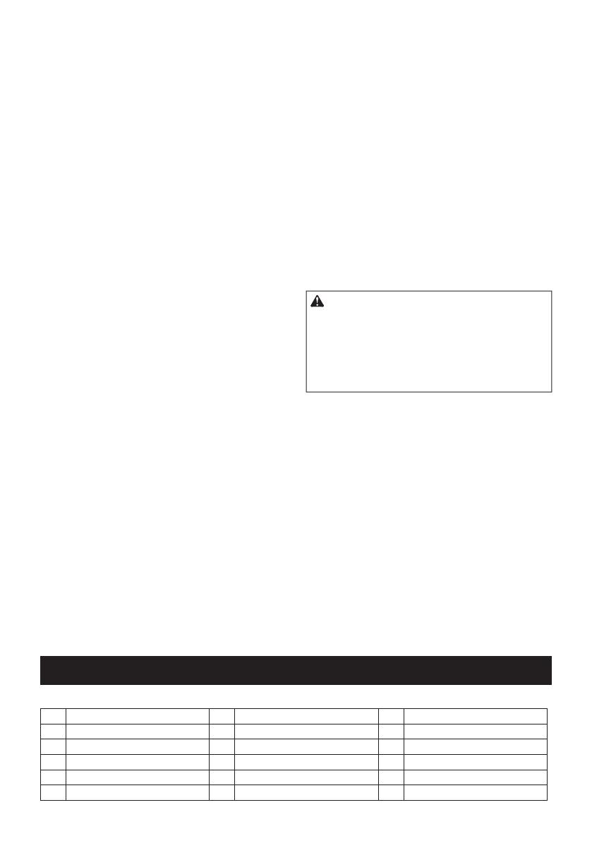
OPIS CZĘŚCI
Rys.1
1Spust przełącznika 2Przycisk blokady 3Przełącznik lampki
4Lampka 5Przycisk blokady spustu 6Pokrętło zmiany trybu prędkości
7Spust powietrza 8Korek wlewu 9Wąż elastyczny
10 Adapter 11 Otwór paska 12 Akumulator
13 Zbiornik 14 Uchwyt pręta 15 Uchwyt węża
16 Ciśnieniowy zawór nadmiarowy 17 Pasek na ramię - -
18 POLSKI
OPIS DZIAŁANIA
PRZESTROGA: Przed przystąpieniem do regu-
lacji lub przeglądu narzędzia upewnić się, że jest
ono wyłączone, a akumulator został wyjęty.
Wkładanie i wyjmowanie
akumulatora
PRZESTROGA: Przed włożeniem lub wyjęciem
akumulatora należy zawsze wyłączyć narzędzie.
PRZESTROGA: Podczas wkładania lub wyjmo-
wania akumulatora należy mocno trzymać narzę-
dzie i akumulator. W przeciwnym razie mogą się one
wyślizgnąć z rąk, powodując uszkodzenie narzędzia
lub akumulatora i obrażenia ciała.
Rys.2: 1. Czerwony wskaźnik 2. Przycisk
3. Akumulator
Aby wyjąć akumulator, przesuń przycisk znajdujący się
w przedniej jego części i wysuń akumulator.
Aby włożyć akumulator, wyrównaj występ na akumulato-
rze z rowkiem w obudowie i wsuń go na swoje miejsce.
Akumulator należy wsunąć do oporu, aż się zatrzaśnie na
miejscu, co jest sygnalizowane delikatnym kliknięciem.
Jeśli w górnej części przycisku jest widoczny czerwony
wskaźnik, akumulator nie został całkowicie zatrzaśnięty.
PRZESTROGA: Akumulator należy włożyć
do końca, tak aby czerwony wskaźnik nie był
widoczny. W przeciwnym razie może przypadkowo
wypaść z narzędzia, powodując obrażenia operatora
lub osób postronnych.
PRZESTROGA: Nie wkładać akumulatora na
siłę. Jeśli akumulator nie daje się swobodnie wsunąć,
oznacza to, że został włożony nieprawidłowo.
Układ zabezpieczenia narzędzia/
akumulatora
Narzędzie jest wyposażone w układ zabezpieczenia
narzędzia/akumulatora. Układ automatycznie odcina
zasilanie silnika w celu wydłużenia trwałości narzędzia
i akumulatora. Narzędzie zostanie automatycznie
zatrzymane podczas pracy w następujących sytuacjach
związanych z narzędziem lub akumulatorem:
Zabezpieczenie przed przeciążeniem
W przypadku obsługi narzędzia/akumulatora w sposób
powodujący nadmiernie wysoki pobór prądu narzędzie
zostanie automatycznie zatrzymane bez ostrzeżenia. W
takiej sytuacji należy wyłączyć narzędzie i zaprzestać
wykonywania czynności powodującej przeciążenie
narzędzia. Następnie należy włączyć narzędzie w celu
jego ponownego uruchomienia.
Zabezpieczenie przed przegrzaniem
W przypadku przegrzania narzędzia lub akumulatora
narzędzie automatycznie się wyłączy i zacznie migać
lampka. W takiej sytuacji należy odczekać, aż narzę-
dzie ostygnie przed ponownym włączeniem narzędzia.
Zabezpieczenie przed nadmiernym
rozładowaniem
Gdy stan naładowania akumulatora stanie się zbyt
niski, narzędzie zostanie automatycznie zatrzymane.
W takiej sytuacji należy wyjąć akumulator z narzędzia i
naładować go.
WSKAZÓWKA: Działanie układu zabezpieczenia
zależy od temperatury otoczenia lub typu i stanu
smaru.
Wskazanie stanu naładowania
akumulatora
Tylko w przypadku akumulatorów ze wskaźnikiem
Rys.3: 1. Lampki wskaźnika 2. Przycisk kontrolny
Nacisnąć przycisk kontrolny na akumulatorze w celu
wyświetlenia stanu naładowania akumulatora. Lampki
wskaźnika zaświecą się przez kilka sekund.
Lampki wskaźnika Pozostała
energia
akumulatora
Świeci się Wyłączony Miga
75–100%
50–75%
25–50%
0–25%
Naładować
akumulator.
Akumulator
może nie
działać
poprawnie.
WSKAZÓWKA: Zależnie od warunków użytkowania
i temperatury otoczenia, wskazywany poziom może
nieznacznie się różnić od rzeczywistego stanu nała-
dowania akumulatora.
WSKAZÓWKA: Pierwsza (skrajnie po lewej stronie)
lampka wskaźnika miga, gdy układ zabezpieczenia
akumulatora jest aktywny.
Działanie przełącznika
PRZESTROGA: Przed włożeniem akumulatora
do narzędzia należy zawsze sprawdzić, czy spust
przełącznika działa prawidłowo i czy powraca do
położenia wyłączenia po jego zwolnieniu.
PRZESTROGA: Jeżeli narzędzie nie będzie uży-
wane, należy wcisnąć przycisk blokady spustu od
strony „A”, aby zablokować spust przełącznika w
pozycji wyłączenia.
19 POLSKI
Narzędzie zostało wyposażone w przycisk blokady
spustu, który zapobiega przypadkowemu pociągnięciu
za spust przełącznika.
Aby uruchomić narzędzie, należy wcisnąć przycisk
blokady spustu od strony „B” i pociągnąć spust
przełącznika.
Prędkość narzędzia zwiększa się wraz ze zwiększa-
niem nacisku na spust przełącznika. W celu zatrzy-
mania narzędzia zwolnić spust przełącznika. Po pracy
należy zawsze wcisnąć przycisk blokady spustu od
strony „A”.
Aby włączyć tryb pracy ciągłej, należy pociągnąć spust
przełącznika, a następnie nacisnąć przycisk blokady.
Aby odblokować narzędzie, należy pociągnąć do oporu
spust przełącznika.
Rys.4: 1. Spust przełącznika 2. Przycisk blokady
3. Przycisk blokady spustu
Włączanie lampki czołowej
PRZESTROGA: Nie patrzeć na światło ani
bezpośrednio na źródło światła.
W celu włączenia lampki należy nacisnąć przełącznik
lampki. Aby włączyć lampkę, należy ponownie naci-
snąć przełącznik lampki. Jeśli narzędzie z wyłączonym
silnikiem nie będzie używane przez około 60 sekund,
lampka zgaśnie.
Rys.5: 1. Lampka 2. Przełącznik lampki
UWAGA: Aby usunąć zabrudzenia z klosza lampki,
należy użyć suchej szmatki. Uważać, aby nie zaryso-
wać klosza lampki, gdyż może to zmniejszyć natęże-
nie oświetlenia.
Wybór trybu prędkości
UWAGA: Tryb prędkości można zmienić tylko po
całkowitym zatrzymaniu narzędzia.
W narzędziu zamontowane jest pokrętło zmiany trybu
prędkości. Należy przekręcić pokrętło, tak aby znaj-
dująca się na nim strzałka wskazywała jeden z dwóch
trybów, zgodnie z poniższym rysunkiem:
1Tryb małej prędkości: Smar dozowany jest ze stałą
małą prędkością.
2Tryb prędkości automatycznej: Smar nanoszony
jest automatycznie ze zmienną prędkością przepływu,
w zależności od ciśnienia w miejscu docelowym
podawania.
Rys.6: 1. Pokrętło zmiany trybu prędkości
Ciśnieniowy zawór nadmiarowy
Jeśli ciśnienie wewnętrzne narzędzia przekracza
określony poziom, smar wydostaje się z ciśnieniowego
zaworu nadmiarowego w celu obniżenia ciśnienia
wewnętrznego.
Rys.7: 1. Ciśnieniowy zawór nadmiarowy
PRZESTROGA: Jeśli smar wydostanie się z
ciśnieniowego zaworu nadmiarowego, należy go
powycierać np. suchą ściereczką. W przeciwnym
razie może dojść do ślizgania się, co może być przy-
czyną obrażeń.
MONT
PRZESTROGA: Przed przystąpieniem do prac
konserwacyjnych przy narzędziu upewnić się,
że jest ono wyłączone, a akumulator został wyjęty.
Demontaż i montaż zbiornika
Aby wymontować zbiornik, należy przekręcić go w
pokazany sposób.
Rys.8: 1. Zbiornik
Aby zamontować zbiornik, należy włożyć go do narzę-
dzia i przykręcić w odwrotnym kierunku.
Rys.9: 1. Zbiornik
Uchwyt pręta
Podczas doprowadzania smaru do zbiornika należy
pociągnąć za uchwyt pręta.
Rys.10: 1. Uchwyt pręta 2. Pręt
Aby zablokować uchwyt pręta po całkowitym wyciągnięciu go,
należy pociągnąć uchwyt, tak aby widoczny był rowek na pręcie,
a następnie zaczepić rowek w szczelinie. Aby odblokować uchwyt
pręta, odczepić rowek, tak aby pręt przesunął się do przodu.
Rys.11: 1. Rowek 2. Szczelina
PRZESTROGA: Należy upewnić się, czy uchwyt
pręta jest pewnie zablokowany. W przeciwnym
razie może się przypadkowo odblokować i doprowa-
dzić do zakleszczenia.
WSKAZÓWKA: Aby pociągnąć za uchwyt pręta,
gdy zbiornik jest zamontowany w narzędziu, należy
poluzować zawór spustu powietrza, aby powietrze
wydostało się ze zbiornika.
Uchwyt węża
Uchwyt węża można przymocować z boku narzędzia z
jednej lub z drugiej strony za pomocą śruby.
Rys.12: 1. Uchwyt węża 2. Śruba
Pasek na ramię
OSTRZEŻENIE: Nigdy nie należy używać
otworu paska do mocowania pasa asekuracyj-
nego (linki do mocowania). Może to spowodować
poważne obrażenia, ponieważ otwór paska nie jest
przeznaczony do mocowania urządzeń zabezpiecza-
jących przed upadkiem.
OSTRZEŻENIE: Podczas przenoszenia
narzędzia należy je przytrzymywać, nawet jeśli
używany jest pasek na ramię. Przenoszenie narzę-
dzia tylko za pomocą paska na ramię sprawia, że jest
ono niestabilne. Pasek na ramię może się ześlizgnąć
lub narzędzie może uderzyć o inny przedmiot i spo-
wodować obrażenia.
Zaczepy paska na ramię należy zamocować do mocowań
w otworach paska w sposób przedstawiony na rysunku.
Rys.13: 1. Pasek na ramię 2. Zaczep 3. Uchwyt
montażowy
20 POLSKI
OBSŁUGA
Podawanie smaru
OSTRZEŻENIE: Należy zapoznać się z
instrukcjami obsługi smaru i/lub innych przyrzą-
dów i w razie konieczności wymienić wymagane
elementy. Nieprawidłowe użycie lub nieprzestrze-
ganie instrukcji może doprowadzić do uszkodzenia
narzędzia lub spowodować obrażenia ciała.
UWAGA: W przypadku używania zbiornika z pozo-
stałościami starego smaru należy wymontować
zbiornik i usunąć stary smar zgodnie z opisem w
punkcie dotyczącym usuwania smaru.
Smar można wprowadzić w następujący sposób:
Montowanie wkładu ze smarem
(dostępny na rynku) w zbiorniku
UWAGA: (Tylko zbiornik typu A)
Używać wkładu ze smarem, którego ramkę można
zawiesić na krawędzi zbiornika.
UWAGA: (Tylko zbiornik typu B/C)
Używać wkładu ze smarem, którego ramkę można
zawiesić na wewnętrznym stopniu zbiornika.
1. Należy wymontować zbiornik z narzędzia, a
następnie pociągnąć za uchwyt pręta do końca zakresu
ruchu i zablokować go.
2. Zdjąć plastikowy korek wkładu ze smarem i wło-
żyć wkład ze smarem do zbiornika.
Rys.14: 1. Wkład ze smarem (dostępny na rynku)
2. Zaczep do wyciągania
3. Usunąć zaczep do wyciągania wkładu ze smarem,
a następnie zamontować zbiornik w narzędziu.
Jeśli między ramką wkładu ze smarem a zbiornikiem
jest odstęp, należy wkręcić zbiornik do narzędzia, naci-
skając zbiornik do przodu.
Rys.15
4. Zwolnić uchwyt pręta.
Rys.16
5.
Usunąć powietrze pozostające na ścieżce przepływu
smaru. (Patrz część dotycząca usuwania powietrza.)
Uzupełnianie smaru w zbiorniku z
opakowania zbiorczego (dostępne na
rynku)
1. Wyjąć zbiornik z narzędzia.
2.
Zanurzyć końcówkę zbiornika w smarze, a następnie pocią-
gnąć za uchwyt pręta. Smar zostaje wpompowany do zbiornika.
Rys.17:
1. Opakowanie zbiorcze (dostępne na rynku)
3. Pociągnąć za uchwyt pręta do końca zakresu
ruchu i zablokować go.
Rys.18
4. Zamontować zbiornik w narzędziu, a następnie
odblokować uchwyt pręta.
5.
Usunąć powietrze pozostające na ścieżce przepływu
smaru. (Patrz część dotycząca usuwania powietrza.)
UWAGA: Podczas blokowania uchwytu pręta
należy upewnić się, czy jest on dokładnie zablo-
kowany. W przeciwnym razie uchwyt pręta może
zostać przypadkowo odblokowany i smar wydostanie
się ze zbiornika.
WSKAZÓWKA: (Tylko zbiornik typu B/C)
Po napełnieniu smar powinien znajdować się
poniżej linii rowka śruby. W przeciwnym razie
dojdzie do przelania smaru podczas montowania
zbiornika w narzędziu.
Rys.19:
1. Zbiornik (typ B/C) 2. Rowek śruby 3. Smar
Można również napełnić zbiornik smarem za
pomocą pompy do napełniania (dostępna na rynku),
która jest podłączana do opakowania zbiorczego.
1. Należy zdjąć korek wlewu. Zamocować złączkę
podającą (dostępna na rynku) do wlewu.
2. Po zamocowaniu zbiornika w narzędziu podłączyć
złączkę podającą do złączki w pompie do napełniania.
Rys.20: 1. Korek wlewu 2. Wlew 3. Złączka poda-
jąca (dostępna na rynku) 4. Pompa do
napełniania (dostępna na rynku) 5. Złączka
3.
Uruchom pompę do napełniania. Pręt uchwytu pręta
zostanie wypchnięty podczas napełniania zbiornika smarem.
Rys.21
4. Odłączyć złączkę podającą od złączki pompy do
napełniania.
5.
Usunąć powietrze pozostające na ścieżce przepływu
smaru. (Patrz część dotycząca usuwania powietrza.)
OSTRZEŻENIE: Należy używać wyłącznie
niskociśnieniowej złączki podającej. Nigdy nie
należy używać wysokociśnieniowej złączki poda-
jącej, ponieważ może to doprowadzić do uszko-
dzenia narzędzia oraz spowodować obrażenia
ciała.
PRZESTROGA: Podczas uzupełniania smaru
za pomocą pompy do napełniania należy mocno
przytrzymać narzędzie. Narzędzie może upaść i
spowodować obrażenia ciała.
UWAGA: Napełnianie smarem należy przerwać,
gdy na pręcie widoczny jest rowek. W przeciwnym
razie może dojść do wycieku smaru.
Usuwanie powietrza
Jeśli na ścieżce przepływu smaru pozostanie powie-
trze, dokładne podawanie smaru za pomocą narzędzia
będzie niemożliwe. Należy usunąć powietrze przed
każdym użyciem oraz w sytuacji, kiedy prawdopo-
dobną przyczyną nieprawidłowej pracy narzędzia jest
powietrze.
1. Aby usunąć powietrze z wnętrza narzędzia, należy
poluzować spust powietrza. Powietrze wydostanie się z
otworu spustu powietrza.
2. Dokręcić zawór, jeśli przez otwór zacznie się
wydostawać smar.
Rys.22: 1. Zawór
  • Page 1 1
  • Page 2 2
  • Page 3 3
  • Page 4 4
  • Page 5 5
  • Page 6 6
  • Page 7 7
  • Page 8 8
  • Page 9 9
  • Page 10 10
  • Page 11 11
  • Page 12 12
  • Page 13 13
  • Page 14 14
  • Page 15 15
  • Page 16 16
  • Page 17 17
  • Page 18 18
  • Page 19 19
  • Page 20 20
  • Page 21 21
  • Page 22 22
  • Page 23 23
  • Page 24 24
  • Page 25 25
  • Page 26 26
  • Page 27 27
  • Page 28 28
  • Page 29 29
  • Page 30 30
  • Page 31 31
  • Page 32 32
  • Page 33 33
  • Page 34 34
  • Page 35 35
  • Page 36 36
  • Page 37 37
  • Page 38 38
  • Page 39 39
  • Page 40 40
  • Page 41 41
  • Page 42 42
  • Page 43 43
  • Page 44 44
  • Page 45 45
  • Page 46 46
  • Page 47 47
  • Page 48 48
  • Page 49 49
  • Page 50 50
  • Page 51 51
  • Page 52 52
  • Page 53 53
  • Page 54 54
  • Page 55 55
  • Page 56 56
  • Page 57 57
  • Page 58 58
  • Page 59 59
  • Page 60 60
  • Page 61 61
  • Page 62 62
  • Page 63 63
  • Page 64 64
  • Page 65 65
  • Page 66 66
  • Page 67 67
  • Page 68 68
  • Page 69 69
  • Page 70 70
  • Page 71 71
  • Page 72 72

Makita DGP180 Ghid de instalare

Tip
Ghid de instalare