Wellis Clarice built-in-cistern Manual de utilizare
- Tip
- Manual de utilizare

CLARICE
EE00273
Clarice built in cistern
INSTALLATION MANUAL
Clarice falsík mögötti WC tartály
SZERELÉSI ÚTMUTATÓ
Clarice in Zisterne gebaut
INSTALLATIONSANLEITUNG
Réservoir encastré Clarice
MANUEL D’INSTALLATION
Rezervor WC încastrat în perete Clarice
INSTRUCȚIUNI DE MONTARE
EN
HU
DE
FR
RO

EN
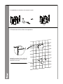
500
1
2"MALE
Min 290
230
180
100 35
Min 1138
0-200
90
A=45/65
1
2
3
4
5
1
2
3
4
5
A=65
A=45
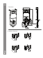
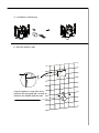
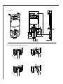
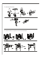
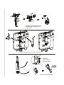
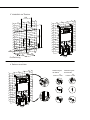
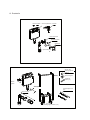
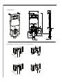
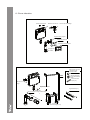
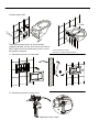
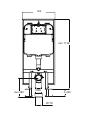
1、Dimenesions:
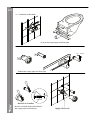
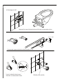
3、Installation of the cistern:
2、Installation of flush bend:
1Installation Instruction (CJ708) 2
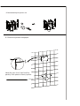
150~200
A
B
460
240
360.5
1000
1120
300
45~65
max190
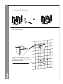
Positioning
190
10
AB
10
4、Adjust the frame
Position on floor
Position on wall
MAX 380
Ø110

500
1
2"MALE
Min 290
230
180
100 35
Min 1138
0-200
90
A=45/65
1
2
3
4
5
1
2
3
4
5
A=65
A=45
1、Dimenesions:3、Installation of the cistern:
2、Installation of flush bend:
1Installation Instruction (CJ708) 2
150~200
A
B
460
240
360.5
1000
1120
300
45~65
max190
Positioning
190
10
AB
10
4、Adjust the frame
Position on floor
Position on wall
MAX 380
Ø110
500
1
2"MALE
Min 290
230
180
100 35
Min 1138
0-200
90
A=45/65
1
2
3
4
5
1
2
3
4
5
A=65
A=45
1、Dimenesions:
3、Installation of the cistern:
2、Installation of flush bend:
1Installation Instruction (CJ708)
2
150~200
A
B
460
240
360.5
1000
1120
300
45~65
max190
Positioning
190
10
AB
10
4、Adjust the frame
Position on floor
Position on wall
MAX 380
Ø110

3
3
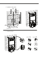
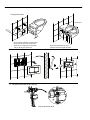
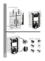
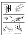
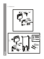
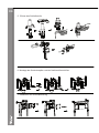
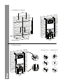
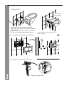
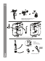
9、Build the partition wall:
keep the space no less than 3mm
between the plug and wall ,as well as
between the sheath and the wall
8、Installation of bend plug:
6、Installation of the threaded rod kits and flexible sheath:
7、Installation of protective case:
5、Installation of the stop valve:
3
4
EN

3
3
9、Build the partition wall:
keep the space no less than 3mm
between the plug and wall ,as well as
between the sheath and the wall
8、Installation of bend plug:
6、Installation of the threaded rod kits and flexible sheath:
7、Installation of protective case:
5、Installation of the stop valve:
3
4

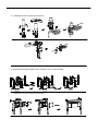
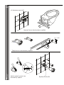
L1+ 6 mm
L1
L2 L2+3 mm
cc/2
45
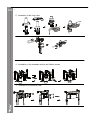
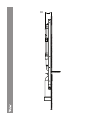
Burnish a chamfer on the head face of
the supply pipe and ush pipe
Reduce the supply pipe and ush pipe
Draw on the supply pipe and ush pipe
Apply silicon oil
burnish a chamfer
A+25mm
1
2
3
45
-
+
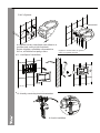
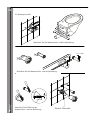
11、Installation of control plate :
Fix the threaded rod kits and
adjust the toilet to right position
After removing exible sheath,adjust
the threaded rod exposed outside
.Then x the supply pipe onto toilet
and the ush pipe onto wall
Gradienter
12、Maintenance of the cistern ttings :
Adjust the water level
5
6
10、Installation of the toilet :
Fixing of the toilet
A
EN

L1+ 6 mm
L1
L2 L2+3 mm
cc/2
45
Burnish a chamfer on the head face of
the supply pipe and ush pipe
Reduce the supply pipe and ush pipe
Draw on the supply pipe and ush pipe
Apply silicon oil
burnish a chamfer
A+25mm
1
2
3
45
-
+
11、Installation of control plate :
Fix the threaded rod kits and
adjust the toilet to right position
After removing exible sheath,adjust
the threaded rod exposed outside
.Then x the supply pipe onto toilet
and the ush pipe onto wall
Gradienter
12、Maintenance of the cistern ttings :
Adjust the water level
5
6
10、Installation of the toilet :
Fixing of the toilet
A

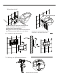
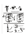
8
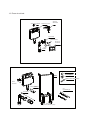
Seal
7L.
6L.
Wash the ll valve if the water lling
gets slow or unstoppable
Installation & remove the ush valve
Adjust the water level
of the ush valve
Maintenance of the seal
FLUSH VALVE
CISTERN'S PLATE
BRACKETT FOR LEVER
STOP VALVE
84mm CISTERN
FILL VALVE
CONTROL PLATE
FLEXIIBLE SHEATH(X2)
FLUSH BEND PLUG
SUPPLY BEND PLUG
FLUSH PIPE
THREADED ROD KITS(X2)
FLUSH BEND
ATTACHMENT
KITS
7
8
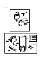
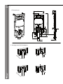
13、Spare parts :
ATTACHING
SCREW(X10)
FRAME
EN

8
Seal
7L.
6L.
Wash the ll valve if the water lling
gets slow or unstoppable
Installation & remove the ush valve
Adjust the water level
of the ush valve
Maintenance of the seal
FLUSH VALVE
CISTERN'S PLATE
BRACKETT FOR LEVER
STOP VALVE
84mm CISTERN
FILL VALVE
CONTROL PLATE
FLEXIIBLE SHEATH(X2)
FLUSH BEND PLUG
SUPPLY BEND PLUG
FLUSH PIPE
THREADED ROD KITS(X2)
FLUSH BEND
ATTACHMENT
KITS
78
13、Spare parts :
ATTACHING
SCREW(X10)
FRAME

Clarice falsík mögötti WC tartály
SZERELÉSI ÚTMUTATÓ
HU

Clarice falsík mögötti WC tartály
SZERELÉSI ÚTMUTATÓ
EN
500
1
2"MALE
Min 290
230
180
100 35
Min 1138
0-200
90
A=45/65
1
2
3
4
5
1
2
3
4
5
A=65
A=45
1、Dimenesions:
3、Installation of the cistern:
2、Installation of flush bend:
1Installation Instruction (CJ708)
2
150~200
A
B
460
240
360.5
1000
1120
300
45~65
max190
Positioning
190
10
AB
10
4、Adjust the frame
Position on floor
Position on wall
MAX 380
Ø110
1. Méretek
2. Az öblítőcső könyökének felszerelése
apa
HU

500
1
2"MALE
Min 290
230
180
100 35
Min 1138
0-200
90
A=45/65
1
2
3
4
5
1
2
3
4
5
A=65
A=45
1、Dimenesions:
3、Installation of the cistern:
2、Installation of flush bend:
1Installation Instruction (CJ708)
2
150~200
A
B
460
240
360.5
1000
1120
300
45~65
max190
Positioning
190
10
AB
10
4、Adjust the frame
Position on floor
Position on wall
MAX 380
Ø110
3. A víztároló felszerelése
Pozicionálás
4. A keret igazítása
Elhelyezés a
falon Elhelyezés a
padlón

3
3
9、Build the partition wall:
keep the space no less than 3mm
between the plug and wall ,as well as
between the sheath and the wall
8、Installation of bend plug:
6、Installation of the threaded rod kits and flexible sheath:
7、Installation of protective case:
5、Installation of the stop valve:
3
4
5. A zárószelep felszerelése
6. A menetes szárak és a rugalmas szorító hüvely felszerelése
7. A védőburkolat felszerelése
HU

3
3
9、Build the partition wall:
keep the space no less than 3mm
between the plug and wall ,as well as
between the sheath and the wall
8、Installation of bend plug:
6、Installation of the threaded rod kits and flexible sheath:
7、Installation of protective case:
5、Installation of the stop valve:
3
4
8. A könyökdugó felszerelése
9. A válaszfal építése
Hagyjon helyet legalább 3 mm-re a
csatlakozó és a fal között, valamint a
hüvely és a fal között

L1+ 6 mm
L1
L2 L2+3 mm
cc/2
45
Burnish a chamfer on the head face of
the supply pipe and ush pipe
Reduce the supply pipe and ush pipe
Draw on the supply pipe and ush pipe
Apply silicon oil
burnish a chamfer
A+25mm
1
2
3
45
-
+
11、Installation of control plate :
Fix the threaded rod kits and
adjust the toilet to right position
After removing exible sheath,adjust
the threaded rod exposed outside
.Then x the supply pipe onto toilet
and the ush pipe onto wall
Gradienter
12、Maintenance of the cistern ttings :
Adjust the water level
5
6
10、Installation of the toilet :
Fixing of the toilet
A
10. A WC felszerelése
A vízellátás csővezetékét és az öblítőcsövet jelölje fel
A vízellátás csővezetékét és az öblítőcsövet vágja le
Csiszolja le a vízellátás
csővezetékét és az öblítőcső elejét Alkalmazzon szilikonolajat
HU

L1+ 6 mm
L1
L2 L2+3 mm
cc/2
45
Burnish a chamfer on the head face of
the supply pipe and ush pipe
Reduce the supply pipe and ush pipe
Draw on the supply pipe and ush pipe
Apply silicon oil
burnish a chamfer
A+25mm
1
2
3
45
-
+
11、Installation of control plate :
Fix the threaded rod kits and
adjust the toilet to right position
After removing exible sheath,adjust
the threaded rod exposed outside
.Then x the supply pipe onto toilet
and the ush pipe onto wall
Gradienter
12、Maintenance of the cistern ttings :
Adjust the water level
5
6
10、Installation of the toilet :
Fixing of the toilet
A
A WC rögzítése
A rugalmas hüvely eltávolítása után állítsa be a
menetes szár, amely kívülről elérhető.
Ezután rögzítse a vízellátás csővezetékét a
WC-re, az öblítőcsövet padig a falra.
12. A tartály szerelvényeinek karbantartása
11. vezérlőpanel installálása
A vízszint beállítása
Rögzítse a menetes szárat, és igazítsa
a WC-t a megfelelő pozícióba.
vízszintmérő

8
Seal
7L.
6L.
Wash the ll valve if the water lling
gets slow or unstoppable
Installation & remove the ush valve
Adjust the water level
of the ush valve
Maintenance of the seal
FLUSH VALVE
CISTERN'S PLATE
BRACKETT FOR LEVER
STOP VALVE
84mm CISTERN
FILL VALVE
CONTROL PLATE
FLEXIIBLE SHEATH(X2)
FLUSH BEND PLUG
SUPPLY BEND PLUG
FLUSH PIPE
THREADED ROD KITS(X2)
FLUSH BEND
ATTACHMENT
KITS
78
13、Spare parts :
ATTACHING
SCREW(X10)
FRAME
EN
Mossa le a töltőszelepet, ha a
víztöltés lassú vagy nem zár
megfelelően
Az öblítőszelep felszerelése és eltávolítása
Állítsa be
a víz szintjét az
öblítőszelepen
Tömítés
A tömítés karbantartása
HU

8
Seal
7L.
6L.
Wash the ll valve if the water lling
gets slow or unstoppable
Installation & remove the ush valve
Adjust the water level
of the ush valve
Maintenance of the seal
FLUSH VALVE
CISTERN'S PLATE
BRACKETT FOR LEVER
STOP VALVE
84mm CISTERN
FILL VALVE
CONTROL PLATE
FLEXIIBLE SHEATH(X2)
FLUSH BEND PLUG
SUPPLY BEND PLUG
FLUSH PIPE
THREADED ROD KITS(X2)
FLUSH BEND
ATTACHMENT
KITS
78
13、Spare parts :
ATTACHING
SCREW(X10)
FRAME
13. Pótalkatrészek
Zárószelep 84mm tartály töltőszelep
a kar tartója
a tartálylemez
vezérlőpanel
öblítőszelep
rögzítő-
készletek
öblítőcső
öblítőcsönyök
keret
ellátócsőkönyök dugója
öblítőcsőkönyök dugója
rugalmas hüvely (2x)
menetes
szárkészlet (2x)
Rögzítőcsavarok (10x)

Clarice in Zisterne gebaut
INSTALLATIONSANLEITUNG
DE

DE
500
1
2"MALE
Min 290
230
180
100 35
Min 1138
0-200
90
A=45/65
1
2
3
4
5
1
2
3
4
5
A=65
A=45
1、Dimenesions:
3、Installation of the cistern:
2、Installation of flush bend:
1Installation Instruction (CJ708)
2
150~200
A
B
460
240
360.5
1000
1120
300
45~65
max190
Positioning
190
10
AB
10
4、Adjust the frame
Position on floor
Position on wall
MAX 380
Ø110
1. Dimensionen
2. Montage des Spülrohrbogens
Externer Thread
DE
Pagina se încarcă...
Pagina se încarcă...
Pagina se încarcă...
Pagina se încarcă...
Pagina se încarcă...
Pagina se încarcă...
Pagina se încarcă...
Pagina se încarcă...
Pagina se încarcă...
Pagina se încarcă...
Pagina se încarcă...
Pagina se încarcă...
Pagina se încarcă...
Pagina se încarcă...
Pagina se încarcă...
Pagina se încarcă...
Pagina se încarcă...
Pagina se încarcă...
Pagina se încarcă...
Pagina se încarcă...
Pagina se încarcă...
Pagina se încarcă...
Pagina se încarcă...
Pagina se încarcă...
Pagina se încarcă...
Pagina se încarcă...
Pagina se încarcă...
Pagina se încarcă...
-
 1
1
-
 2
2
-
 3
3
-
 4
4
-
 5
5
-
 6
6
-
 7
7
-
 8
8
-
 9
9
-
 10
10
-
 11
11
-
 12
12
-
 13
13
-
 14
14
-
 15
15
-
 16
16
-
 17
17
-
 18
18
-
 19
19
-
 20
20
-
 21
21
-
 22
22
-
 23
23
-
 24
24
-
 25
25
-
 26
26
-
 27
27
-
 28
28
-
 29
29
-
 30
30
-
 31
31
-
 32
32
-
 33
33
-
 34
34
-
 35
35
-
 36
36
-
 37
37
-
 38
38
-
 39
39
-
 40
40
-
 41
41
-
 42
42
-
 43
43
-
 44
44
-
 45
45
-
 46
46
-
 47
47
-
 48
48


Wellis Clarice built-in-cistern Manual de utilizare
- Tip
- Manual de utilizare
în alte limbi
Lucrări înrudite


Alte documente
-
DAB FEKALIFT 200-A Instruction For Installation And Maintenance
-
Sames ISOCUBE pour Nanogun Airspray H2O Manual de utilizare
-
-
-
-
-
-
-
-