
1
PD Scan
Online Partial Discharge Handheld Scanner
USER GUIDE
Issue: B (07/2019) - EN
Article number: 86391

2

Consultation with Megger
3
Consultation with Megger
The present system manual has been designed as an operating guide and for
reference. It is meant to answer your questions and solve your problems in as fast and
easy a way as possible. Please start with referring to this manual should any trouble
occur.
In doing so, make use of the table of contents and read the relevant paragraph with
great attention. Furthermore, check all terminals and connections of the instruments
involved.
Should any question remain unanswered or should you need the help of an authorized
service station, please contact:
Megger Limited Seba Dynatronic
Mess- und Ortungstechnik GmbH
Archcliffe Road
Kent CT17 9EN
T: +44 1304 502100
F: +44 1304 207342
E: uksales@megger.com
Dr.-Herbert-Iann-Str. 6
D - 96148 Baunach
T: +49 9544 68 – 0
F: +49 9544 22 73
E: team.dach@megger.com
Hagenuk KMT
Kabelmesstechnik GmbH
Megger USA
Röderaue 41
D - 01471 Radeburg / Dresden
T: +49 35208 84 – 0
F: +49 35208 84 249
E: team.dach@megger.com
Valley Forge Corporate Centre
2621 Van Buren Avenue
Norristown, PA 19403 USA
T: +1 610 676 8500
F: +1 610 676 8610
Megger
All rights reserved. No part of this handbook may be copied by photographic or other means unless Megger
have before-hand declared their consent in writing. The content of this handbook is subject to change without
notice. Megger cannot be made liable for technical or printing errors or shortcomings of this handbook.
Megger also disclaims all responsibility for damage resulting directly or indirectly from the delivery, supply, or
use of this matter.

Terms of Warranty
4
Terms of Warranty
Megger accept responsibility for a claim under warranty brought forward by a customer
for a product sold by Megger under the terms stated below.
Megger warrant that at the time of delivery Megger products are free from manufacturing
or material defects which might considerably reduce their value or usability. This
warranty does not apply to faults in the software supplied. During the period of warranty,
Megger agree to repair faulty parts or replace them with new parts or parts as new (with
the same usability and life as new parts) according to their choice.
This warranty does not cover wear parts, lamps, fuses, batteries and accumulators.
Megger reject all further claims under warranty, in particular those from consequential
damage. Each component and product replaced in accordance with this warranty
becomes the property of Megger.
All warranty claims versus Megger are hereby limited to a period of 12 months from the
date of delivery. Each component supplied by Megger within the context of warranty will
also be covered by this warranty for the remaining period of time but for 90 days at
least.
Each measure to remedy a claim under warranty shall exclusively be carried out by
Megger or an authorized service station.
This warranty does not apply to any fault or damage caused by exposing a product to
conditions not in accordance with this specification, by storing, transporting, or using it
improperly, or having it serviced or installed by a workshop not authorized by Megger.
All responsibility is disclaimed for damage due to wear, will of God, or connection to
foreign components.
For damage resulting from a violation of their duty to repair or re-supply items, Megger
can be made liable only in case of severe negligence or intention. Any liability for slight
negligence is disclaimed.
Since some states do not allow the exclusion or limitation of an implied warranty or of
consequential damage, the limitations of liability described above perhaps may not
apply to you.

Contents
5
Contents
Consultation with Megger ............................................................................................... 3
Terms of Warranty ........................................................................................................... 4
Contents ........................................................................................................................... 5
General Notes .................................................................................................................. 7
1 Technical description ...................................................................................... 9
1.1 System description ............................................................................................. 9
1.2 Technical data .................................................................................................. 12
1.3 Connection, display and control elements ....................................................... 14
2 Principles of operation .................................................................................. 15
2.1 General operation ............................................................................................. 15
3 Using/attaching the sensors provided ......................................................... 18
4 Performing measurements ............................................................................ 22
4.1 First steps ......................................................................................................... 22
4.2 Preparing a measurement ................................................................................ 25
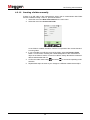
4.2.1 Creating a measurement data folder ................................................................ 26
4.2.1.1 Scanning the QR code on the measurement object ........................................ 26
4.2.1.2 Creating a folder manually ............................................................................... 28
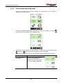
4.2.2 Selecting the operating mode .......................................................................... 29
4.3 Measuring the ambient noise level ................................................................... 31
4.4 Standard measurement .................................................................................... 32
4.5 TEV comparative measurement between an internal and external sensor ..... 36
4.6 TEV measurement sequence ........................................................................... 38
4.7 Evaluation of the measurement results ............................................................ 40
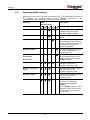
5 Settings ........................................................................................................... 42
5.1 Device settings ................................................................................................. 43
5.1.1 Importing and exporting configuration and comparison data ........................... 44
5.1.2 Pairing Bluetooth headphones ......................................................................... 46
5.2 Operating mode settings .................................................................................. 47
5.3 Adjusting the evaluation thresholds ................................................................. 49
5.4 PRPD diagram display settings ........................................................................ 50
5.5 System information ........................................................................................... 51
6 Processing the measured data ..................................................................... 52
6.1 Transmitting measurement data via a wireless network .................................. 52
6.2 Transferring measured data onto a PC ............................................................ 52
6.3 Preparing a report ............................................................................................ 53
7 Using the demonstrator box ......................................................................... 57

Contents
6
8 Maintenance and care .................................................................................... 60
9 Troubleshooting ............................................................................................. 62

General Notes
7
General Notes
This manual contains basic instructions for the commissioning and operation of the
device / system. For this reason, it is important to ensure that the manual is always
available to the authorised and trained operator. He needs to read the manual
thoroughly. The manufacturer is not liable for damage to material or humans due to non-
observance of the instructions and safety advices provided by this manual.
Locally applying regulations have to be observed!
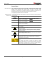
The following signal words and symbols are used in this instruction manual and also on
the product itself:
Signal word /
symbol
Description
DANGER
Indicates a potential danger that will lead to fatal or serious
injuries, if it is not avoided.
WARNING
Indicates a potential danger that may lead to fatal or serious
injuries, if it is not avoided.
CAUTION
Indicates a potential danger that may lead to moderate or minor
injuries, if it is not avoided.
NOTE
Indicates a potential danger that may lead to material damage, if it
is not avoided.
Serves to highlight warning and safety information in the
instruction manual.
A sticker on the product serves to identify the sources of danger
and the safe handling of these dangers is ensured by reading the
instruction manual.
Serves to highlight warning and safety information which explicitly
refers to danger of electric shock.
Serves to highlight important information and useful tips for
operating the product. Failure to observe them can render the
measurement results useless.
The parabolic acoustic sensor AA PR400 is fitted with a class 2
laser.
The available laser beam is therefore only within the
visible
spectral range (650
nm). It is not harmful to the eye in the event of
brief periods of exposure (up to 0.25
sec.). Longer periods of
exposure are prevented by the natural corneal reflex.
Safety precautions
Signal words and
symbols used

General Notes
8
It is important to observe the generally applicable electrical regulations of the country in
which the device will be installed and operated, as well as the current national accident
prevention regulations and internal company directives (work, operating and safety
regulations).
After working on the system, it must be voltage-free and secured against reconnection
as well as having been discharged, earthed and short-circuited.
Use genuine accessories to ensure system safety and reliable operation. The use of
other parts is not permitted and invalidates the warranty.
The system may only be installed and operated by an authorised electrician. DIN VDE
0104 (EN 50191), DIN VDE 0105 (EN 50110) and the German accident prevention
regulations (UVV) define an electrician as someone whose knowledge, experience and
familiarity with the applicable regulations enables him to recognise potential hazards.
Anyone else must be kept away!
The product meets the following security requirements of the European Council
Directives:
• Radio Equipment Directive (RED 2014/53/EU)
• RoHS Directive (2011/65/EU)
• Artificial Optical Radiation Directive (2006/25/EC)
The transportation of lithium batteries, as well as devices in which such batteries or
rechargeable batteries are installed, is governed by regulations that are based on the
model regulations of the United Nations for the transport of dangerous goods on land
(UN document ST/SG/AC.10-1).
Inform yourself about the transport regulations and observe them when transporting the
device.
This product contains protected software, which is licensed under the General Public
License (GPL) and the Lesser General Public License (LGPL). This certifies your right to
request the source code for these software components.
You can find detailed information on the GPL/LGPL licenses under www.gnu.org.
The Bluetooth
®
word mark and logos are registered trademarks owned by Bluetooth
SIG, Inc. and any use of such marks is under license.
The operating safety of the system delivered is only guaranteed in the event of intended
use (see page 9). Incorrect use may expose the operator, the system and any
equipment connected to risks.
The thresholds listed in the technical data may not be exceeded under any
circumstances.
Working with products
from Megger
Operating staff
Declaration of
Conformity (CE)
Device transportation
Use of third party
software
Used trademarks
Intended use

Technical description
9
1 Technical description
1.1 System description
Defects on medium and high voltage components not only require costly repairs, but
can also lead to failures of network sections with associated adverse consequences. It
is therefore in the interest of all network operators to be able to detect signs of imminent
defects as early as possible so as to take suitable countermeasures promptly.
Megger is offering a lightweight, robust and portable measuring device in the form the
PD Scan which allow a range of operating equipment to be examined quickly for partial
discharge signals.
The PD Scan is used for early detection of partial discharges in medium voltage
substations and other electrical operating equipment. The convenient device features
two internal sensors (TEV, airborne acoustic) for this purpose, and can also be operated
with a range of external sensors (TEV, HFCT, airborne acoustic, acoustic contact
probe). The device can be operated by using three soft buttons and by using the touch
display.
All components (sensors and accessories) which may be used with the PD Scan are
described in this manual. The product delivered to customers is, in fact, always a
customer-specific configuration. At present, four versions exist (“Basis” and “Pro”), each
housed in a special case.
The PD Scan combines the following features in one device:
• Measurement of partial discharge signals (inductive, capacitive and acoustic)
• Simple operation using a touchscreen or operating buttons
• High-performance internal rechargeable battery enables long operating time
• USB port
• Function testing
• Integrated camera
• QR code scanner
• Measured data evaluation
• Recording of the measured data and reporting using the MeggerBook Reporting
Edition
Intended use
Performance features

Technical description
10
The PD Scan is available in four different, application-based versions (set 1 to 4).
Depending on the set purchased, the maximum scope of delivery includes the following
components:
Component 1 2 3 4 Item number
PD Scan, handheld PD scanner
1009814
USB stick with instruction manual and reporting
software
2010642
Charger
90025102
USB connection cable, type C
90027768
Headphones + adapter cable
90026232 +
90026230
Bluetooth headphones
90019021
Function tester, FC 1
1010219
Temperature and humidity
sensor (with two additional
protective caps)
1010217
External TEV sensor,
C900-PD
1010524
HFCT sensor, SC40 +
connection cable
1009667 +
90026538
Parabolic acoustic sensor, AA
PR400
1009681
Flexible airborne acoustic
sensor, AA FR130
1009757
Acoustic contact probe,
ACP 30
1010420
Transport case
90031295
Included in delivery

Technical description
11
Check the contents of the package for completeness and visible damage right after
receipt. In the case of visible damage, the device must under no circumstances be taken
into operation. If something is missing or damaged, please contact your local sales
representative.
When required, you can order the following accessory parts and upgrade kits from the
usual sales channels:
Option / Kit Description Item number
Upgrade kit set
1 to set 4
Includes a parabolic acoustic sensor, flexible
acoustic sensor, acoustic contact probe, HFCT
sensor, Bluetooth® headphones and larger
transport case
1011550
Upgrade kit set
2 to set 4
Includes a parabolic acoustic sensor, flexible
acoustic sensor, acoustic contact probe, Bluetooth®
headphones and larger transport case
1011551
PD Scan
demonstrator
box
Incl. transport case and batteries 1011423
Vehicle charging
cable
For charging using a 12 V onboard power supply 90028407
HFCT sensor
HFFCT 20
HFCT sensor for
permanent installation with 20
mm diameter
1006296 +
90026538
Check contents
Optional accessories /
Upgrade kits

Technical description
12
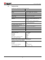
1.2 Technical data
The PD Scan is defined by the following parameters:
Parameter Value
PD Scan Handheld
Display 3.5" touch display, 320 x 240 pixels
Battery Li-ion rechargeable battery; 3.6 V, 3.35 Ah
Operating time >8 hours
Charger input 90 to 264 V AC, 50 / 60 Hz
Charger output 5 V DC
Interfaces USB type C (charging, headphones, PC)
Bluetooth®
Connection socket for external sensors
Memory 32 MB internal memory /
up to 1000 measurements
IP protection class (in accordance with
IEC 60529 (DIN VDE 0470-1))
IP54
Operating temperature -10 to 55 °C; 30 °C 93% r.h.
Storage temperature -20 to 70 °C; 40 °C 95% r.h.
Dimensions W x H x D 220 mm x 80 mm x 30 mm
Weight 420 g
TEV sensors (internal and C900-PD)
Measurement range
Bandwidth
Resolution
Accuracy
Max. number of pulses per cycle
Min. level for pulse counter
-10 to 80 dBmV
2 to 80 MHz
1 dBmV
±1 dBmV
>1226
10 dBmV
Acoustic sensors (internal, AA PR400, AA FR130) and
solid borne vibration sensor ACP 30
Measurement range
Resolution
Accuracy
Converter centre frequency
Laser (AA PR400 only)
-10 to 70 dBµV
1 dB
±1 dB
30, 40 and 80 kHz
Class 2 (max. 1 mW)

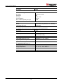
Technical description
13
Parameter Value
HFCT sensor SC40
Measurement range
Bandwidth
Resolution
Accuracy
Input resistance
Max. number of pulses per cycle
-10 to 80 dB
100 kHz to 20 MHz
1 dB
±1 dB / <±10
50 ohms
>1226
Function tester FC1
Battery
Transmitted TEV level
Lithium button cell (CR1216 / 3 V, 25 mAh)
25 dB ±5 dB
The optional demonstrator box is defined by the following parameters:
Parameter Value
Interne Batterien 4 x AA battery
Operating time >50 hours (if standard AA batteries with
2000 mAh are used)
Level of transmitted pulses Adjustable (low, moderate, high, random)
Transmitted pulses per cycle Adjustable (2, 8, 20, random)
Frequency of acoustic pulses 40 kHz
IP protection class (in accordance with
IEC 60529 (DIN VDE 0470-1))
IP42
Operating temperature -10 …. 55 °C; 30°C 93% r.h.
Storage temperature -20 … 70 °C; 40°C 95% r.h.
Dimensions W x H x D 235 x 73 x 135mm
Weight 795 g

Technical description
14
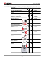
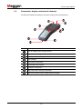
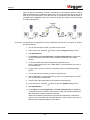
1.3 Connection, display and control elements
The PD Scan features the following connection, display and control elements:
Element Description
LED for displaying the charging activity
Socket for connecting external sensors
On/off switch, back to higher menu level
Touch display
TEV sensor contact area
Camera/QR code scanner
Ultrasonic microphone
Soft buttons with changing functionality
USB port for data transfer, headphones and charger

Principles of operation
15
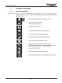
2 Principles of operation
2.1 General operation
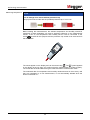
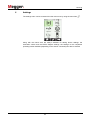
The device can be operated using the touch display or the three soft buttons. Briefly
tapping the screen or the soft button positioned below the required symbol selects the
required function:
Basic operation
•
Exit measuring mode, selection window or menu
•
Select confirm function/setting;
call up selected menu item
• Save the measured values
• Scroll through menu/access required function
• Continue to the next measurement screen
• Switch over to editing mode to change entries
• Undo changes/exit menu without saving
• Keypad control for input of names and numbers
(press briefly: continue to character field or keypad; press
and hold: applies the letters or number selected)
• Start scanning a QR code
• Continues the measurement after pausing
• Jump back one step during a TEV sequence measurement

Principles of operation
16
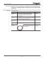
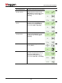
Along with the standard functions which can be accessed using the three buttons at the
lower edge of the display, the following special functions can be activated during the
actual measurement:
Action Function
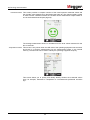
Briefly tapping the
measurement screen
The measurement is paused and the current measurement
results are frozen. If headphones are connected to the
device, then the acoustic, audible signal is also muted.
Instead of the button, the button used to continue
the measurement now appears at the bottom edge of
the screen. Briefly tapping the display again also allows the
measurement to be continued.
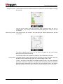
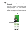
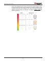
Tapping and holding a
specific segment
The respective settings screen is called up
. This would be
the menu for adjusting the evaluation thresholds in the
example shown.
Once the required settings have been made, the
button is used to the return to the measurement screen.
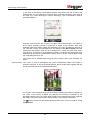
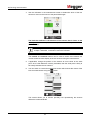
Pressing and holding
the screen selection
button
The current measurement screen is saved as a
screenshot. A keypad for entering the file name appears.
Pressing the button saves the screenshot in the data
folder for the current measurement. The software then
immediately returns to the measurement screen.
The screenshot function is not limited to the measurement
screens and can, for example, also be used in the menu
screens. The only exception are the text entry screens which
cannot be captured as screenshot.
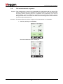
Pressing and holding
the "Save" button
Only available when using an acoustic sensor
An audio stream of the input signal is recorded for
10 seconds. The recording must be started manually by
pressing the button. Pressing the button once
the recording is complete saves the audio stream as a .wav
file in the data folder for the current measurement. If the
desired events are not recorded during the first recording, a
second recording can be started instantly by pressing .
Special functions
during the
measurement

Principles of operation
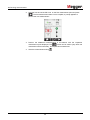
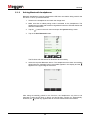
17
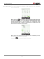
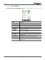
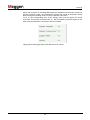
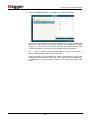
This is used, for example, for the definition of folder names in which the measurement
results should be saved.
Briefly pressing the button allows the user to scroll through the list of fields on the
touch screen. Pressing the button deletes the last character that was entered.
Pressing and holding the button deletes all characters. You can switch to the numeric
keypad by pressing . In addition to number keys, the keypad also has six freely
assignable keys for frequently used text modules.
Briefly pressing a text module adds it to the end of the current character string. Pressing
and holding the text module opens it for editing.
Pressing the button saves the character string entered.
Input using the keypad

Using/attaching the sensors provided
18
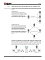
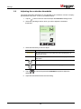
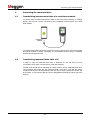
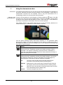
3 Using/attaching the sensors provided
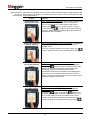
The internal airborne acoustic sensor is used for the acoustic detection of partial
discharges. To do this, the front end of the PD Scan must be aligned with the openings
in the substation, or directly with the freely accessible test object.
The distance to the measurement object should always be roughly the same, when
possible, to ensure the measured values recorded are comparable.
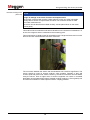
The internal TEV sensor measures electromagnetic waves. To do this, the front end of
the PD Scan is held at the surface of the substation, preferably close to any
openings/gaps in the substation.
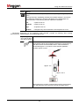
This external, acoustic sensor is specially designed for openings, air holes and gaps,
out of which the acoustic waves of the partial discharges can escape from the
switchgear.
Internal acoustic
sensor
Internal TEV sensor
Flexible
airborne acoustic
sensor

Using/attaching the sensors provided
19
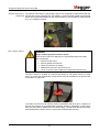
DANGER
Danger of injuries to the eyes due to laser beam
• Avoid direct exposure to the eyes!
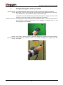
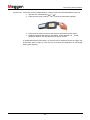
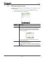
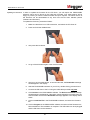
This external sensor is suitable for acoustic measurements indoors or outdoors on
systems on which direct measurements are not possible. The maximum distance
possible is largely dependent on the level of the exciter and the ambient conditions
(humidity, temperature and reflection points). When weather conditions are adverse, the
signal can be attenuated by up to 2 dB/m by the air alone.
Using the parabolic acoustic sensor allows the distance to be increased by around ten
times while retaining the same level in comparison to an internal acoustic receiver. If the
internal acoustic receiver allowed a reading of, for example, 20 dBµV to be taken at a
distance of 1 m to the measurement object, then parabolic acoustic sensor allows the
same level to be recorded at a distance of around 10 m. As for the internal acoustic
sensor, the following applies: The distance to the measurement object should always be
roughly the same, when possible, to ensure the measured values recorded are
comparable.
The sensor features a laser pointer that is activated by pressing a button, and which can
be aligned with the measurement object. This ensures the microphone is optimally
aligned. The parabolic umbrella acts as a light filter and ensures that the red laser point
is easier to detect.
Parabolic acoustic
sensor

Using/attaching the sensors provided
20
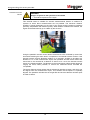
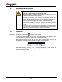
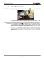
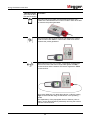
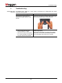
NOTE
Danger of damage in the event of shocks and impact stress
The acoustic contact probe contains a Piezo element, which can suffer irreparable
damage due to shocks or impact stress and which can cause the sensor to make
inaccurate measurements.
The sensor should therefore be treated carefully, and be placed down on the metal
surface gently.
This external sensor measures solid borne vibrations on the surfaces of substations. To
do this, the magnetic sensor is attached to the measuring point.
This measurement is ideally suited for substations with a single enclosure and on which
airborne acoustic measurements cannot be conducted.
The connection between the sensor and the substation has a decisive significance. The
sensor should be used on smooth surfaces, when possible. Particles of dust and
uneven spots that prevent full surface contact by the sensor should be removed before
using the sensor. Even a higher level of surface roughness can result in increased
attenuation of the measurement signal. Suitable coupling media (e.g. silicon grease) can
be used in this situation to make improved sensor coupling possible.
Acoustic contact probe
(ACP 30)
Pagina se încarcă...
Pagina se încarcă...
Pagina se încarcă...
Pagina se încarcă...
Pagina se încarcă...
Pagina se încarcă...
Pagina se încarcă...
Pagina se încarcă...
Pagina se încarcă...
Pagina se încarcă...
Pagina se încarcă...
Pagina se încarcă...
Pagina se încarcă...
Pagina se încarcă...
Pagina se încarcă...
Pagina se încarcă...
Pagina se încarcă...
Pagina se încarcă...
Pagina se încarcă...
Pagina se încarcă...
Pagina se încarcă...
Pagina se încarcă...
Pagina se încarcă...
Pagina se încarcă...
Pagina se încarcă...
Pagina se încarcă...
Pagina se încarcă...
Pagina se încarcă...
Pagina se încarcă...
Pagina se încarcă...
Pagina se încarcă...
Pagina se încarcă...
Pagina se încarcă...
Pagina se încarcă...
Pagina se încarcă...
Pagina se încarcă...
Pagina se încarcă...
Pagina se încarcă...
Pagina se încarcă...
Pagina se încarcă...
Pagina se încarcă...
Pagina se încarcă...
Pagina se încarcă...
-
 1
1
-
 2
2
-
 3
3
-
 4
4
-
 5
5
-
 6
6
-
 7
7
-
 8
8
-
 9
9
-
 10
10
-
 11
11
-
 12
12
-
 13
13
-
 14
14
-
 15
15
-
 16
16
-
 17
17
-
 18
18
-
 19
19
-
 20
20
-
 21
21
-
 22
22
-
 23
23
-
 24
24
-
 25
25
-
 26
26
-
 27
27
-
 28
28
-
 29
29
-
 30
30
-
 31
31
-
 32
32
-
 33
33
-
 34
34
-
 35
35
-
 36
36
-
 37
37
-
 38
38
-
 39
39
-
 40
40
-
 41
41
-
 42
42
-
 43
43
-
 44
44
-
 45
45
-
 46
46
-
 47
47
-
 48
48
-
 49
49
-
 50
50
-
 51
51
-
 52
52
-
 53
53
-
 54
54
-
 55
55
-
 56
56
-
 57
57
-
 58
58
-
 59
59
-
 60
60
-
 61
61
-
 62
62
-
 63
63


în alte limbi
- English: Megger PD Scan User manual
Lucrări înrudite
Alte documente
-
Stanley STHT1-77139RC Manual de utilizare
-
Parkside PLEM 50 B2 Operation and Safety Notes
-
Parkside PLEM 50 A1 Operation and Safety Notes
-
-
Hama 00305098 Manual de utilizare
-
Simplicity MANUAL, OPERATOR'S Manual de utilizare
-
Hama 00205228 Manual de utilizare
-
Chacon 34552 2 Wireless HD Cameras Manual de utilizare
-
Dometic DCC1224, DCC2412, DCC2424 Instrucțiuni de utilizare
-
wtw TetraCon 700-...Ex Series Instrucțiuni de utilizare