
DOC022.98.80116
HQ440d, HQ430d, HQ411d
05/2017, Edition 4
Basic User Manual
Basis-Bedienungsanleitung
Manuale utente di base
Manuel d'utilisation de base
Manual básico del usuario
Manual de operações básicas
Základní uživatelská příručka
Grundlæggende brugervejledning
Basisgebruikershandleiding
Podstawowa instrukcja obsługi
Grundläggande bruksanvisning
Peruskäyttöohje
Основно ръководство за потребителя
Alap felhasználói kézikönyv
Manual de bază al utilizatorului
Bendroji naudotojo instrukcija
Основное руководство пользователя
Temel Kullanıcı Kılavuzu
Základný návod na použitie
Osnovni uporabniški priročnik
Osnovni korisnički priručnik
Βασικό εγχειρίδιο χρήστη
Kokkuvõtlik kasutusjuhend

English..............................................................................................................................3
Deutsch.......................................................................................................................... 18
Italiano............................................................................................................................ 36
Français......................................................................................................................... 54
Español.......................................................................................................................... 72
Português...................................................................................................................... 90
Čeština......................................................................................................................... 108
Dansk............................................................................................................................125
Nederlands................................................................................................................. 142
Polski............................................................................................................................ 160
Svenska....................................................................................................................... 178
Suomi............................................................................................................................196
български................................................................................................................... 213
Magyar......................................................................................................................... 232
Română....................................................................................................................... 250
lietuvių kalba...............................................................................................................268
Русский........................................................................................................................285
Türkçe...........................................................................................................................303
Slovenský jazyk......................................................................................................... 320
Slovenski..................................................................................................................... 338
Hrvatski........................................................................................................................ 356
Ελληνικά...................................................................................................................... 374
eesti keel..................................................................................................................... 393
2

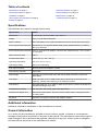
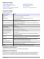
Table of contents
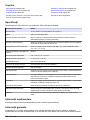
Specifications on page 3
General information on page 3
Installation on page 6
User interface and navigation on page 8
Startup on page 10
Standard operation on page 11
Data management on page 12
Maintenance on page 15
Troubleshooting on page 16
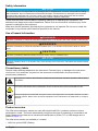
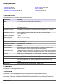
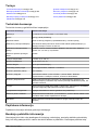
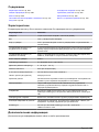
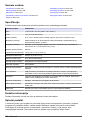
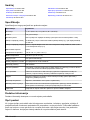
Specifications
Specifications are subject to change without notice.
Specification Details
Dimensions 17.48 x 8.59 x 23.5 cm (6.88 x 3.38 x 9.25 in.)
Weight 750 g (1.65 lb) without batteries
Meter enclosure IP54 with battery cover in place (resistant to intrusion of dust and water spray)
Power requirements (internal) AA Alkaline or rechargeable Nickel Metal Hydride (NiMH) batteries (4); battery
life: up to 200 hours
Power requirements (external) Class II, external power adapter: 100–240 VAC, 50/60 Hz input; 4.5 to 7.5 VDC
(7 VA) output
Meter protection class Class I
Storage temperature –20 to +60 °C (–4 to +140 °F)
Operating temperature 5 to 45 °C (41 to 113 °F)
Operating humidity 90% (non-condensing)
5-pin input connector M12 connector for IntelliCAL
™
probes
Data memory (internal) 500 results
Data storage Automatic in Press to Read mode and Interval Mode. Manual in Continuous
Read Mode.
Data export USB connection to PC or USB storage device (limited to the storage device
capacity). Transfer entire data log or as readings are taken.
Connections Integrated USB type A (for USB 2.0 flash memory device, printer, keyboard) and
Integrated USB type B (for PC)
Temperature correction Off, automatic and manual (parameter dependent)
Measurement display lock Continuous measurement, Interval or Press to Read mode. Averaging function
for LDO probes.
Keyboard External PC keyboard connector with USB/DC adapter
Additional information
Additional information is available on the manufacturer's website.
General information
In no event will the manufacturer be liable for direct, indirect, special, incidental or consequential
damages resulting from any defect or omission in this manual. The manufacturer reserves the right to
make changes in this manual and the products it describes at any time, without notice or obligation.
Revised editions are found on the manufacturer’s website.
English
3

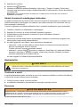
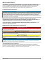
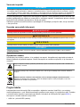
Safety information
N O T I C E
The manufacturer is not responsible for any damages due to misapplication or misuse of this product including,
without limitation, direct, incidental and consequential damages, and disclaims such damages to the full extent
permitted under applicable law. The user is solely responsible to identify critical application risks and install
appropriate mechanisms to protect processes during a possible equipment malfunction.
Please read this entire manual before unpacking, setting up or operating this equipment. Pay
attention to all danger and caution statements. Failure to do so could result in serious injury to the
operator or damage to the equipment.
Make sure that the protection provided by this equipment is not impaired. Do not use or install this
equipment in any manner other than that specified in this manual.
Use of hazard information
D A N G E R
Indicates a potentially or imminently hazardous situation which, if not avoided, will result in death or serious injury.
W A R N I N G
Indicates a potentially or imminently hazardous situation which, if not avoided, could result in death or serious
injury.
C A U T I O N
Indicates a potentially hazardous situation that may result in minor or moderate injury.
N O T I C E
Indicates a situation which, if not avoided, may cause damage to the instrument. Information that requires special
emphasis.
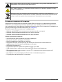
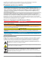
Precautionary labels
Read all labels and tags attached to the instrument. Personal injury or damage to the instrument
could occur if not observed. A symbol on the instrument is referenced in the manual with a
precautionary statement.
This symbol, if noted on the instrument, references the instruction manual for operation and/or safety
information.
This symbol indicates that the marked item can be hot and should not be touched without care.
Electrical equipment marked with this symbol may not be disposed of in European domestic or public
disposal systems. Return old or end-of-life equipment to the manufacturer for disposal at no charge to
the user.
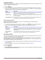
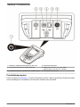
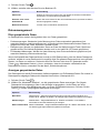
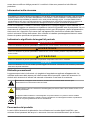
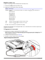
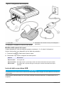
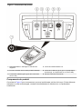
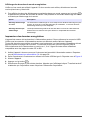
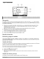
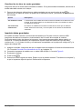
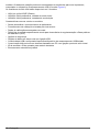
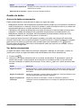
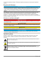
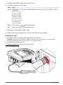
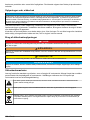
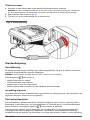
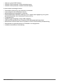
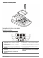
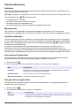
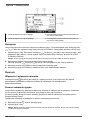
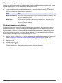
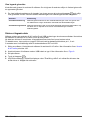
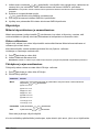
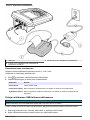
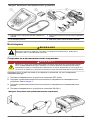
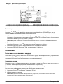
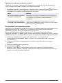
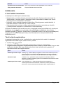
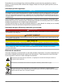
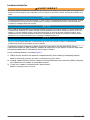
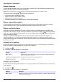
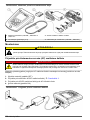
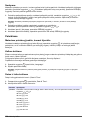
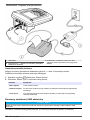
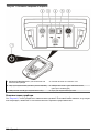
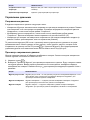
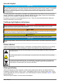
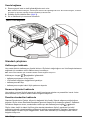
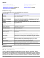
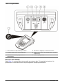
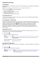
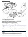
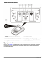
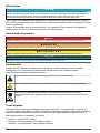
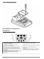
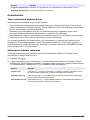
Product overview
The HQd series laboratory meters are used with digital IntelliCAL
™
probes to measure various
parameters in water. The meter automatically recognizes the type of probe that is connected to the
meter. Measurement data can be stored and transferred to a printer, PC or USB storage device
(Refer to Figure 1).
The HQd series meters are available in 3 models:
• HQ411d—pH/mV/ORP (Redox)
4
English

• HQ430d—Multi-parameter, single probe input
• HQ440d—Multi-parameter, dual probe inputs
Features common to all models:
• Automatic probe and parameter recognition
• Instrument guided calibration procedures
• Calibration data stored in the probe
• Probe specific method settings for regulatory compliance and Good Laboratory Practice (GLP)
• Security Options
• Real-time data logging with a USB connection
• USB connectivity to PC/printer/USB storage device/keyboard
• Bi-directional communication with PC-based systems with a virtual serial port connection
• Sample ID and Operator ID for data traceability
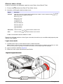
• Adjustable automatic shut-off
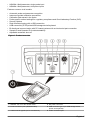
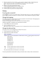
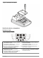
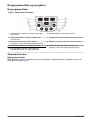
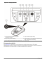
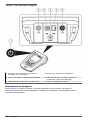
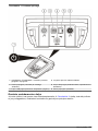
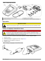
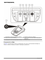
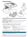
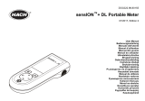
Figure 1 Product overview
1 ON/OFF: turn on or turn off the meter 4 DC power connector
2 Probe connection port (HQ440d model) 5 USB connector type A (for USB storage device,
printer and keyboard)
3 USB connector type B (for PC connections) 6 Probe connection port
English 5

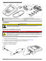
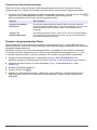
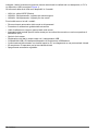
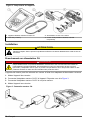
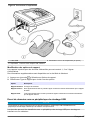
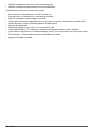
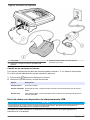
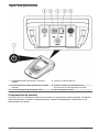
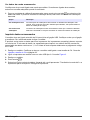
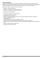
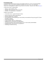
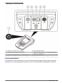
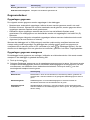
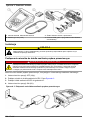
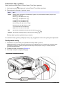
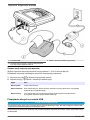
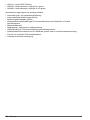
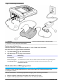
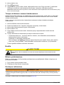
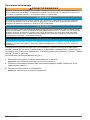
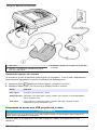
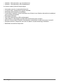
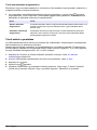
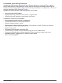
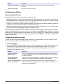
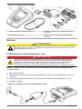
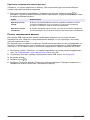
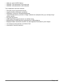
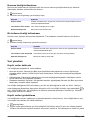
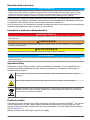
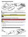
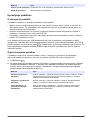
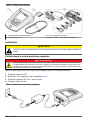
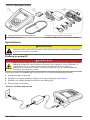
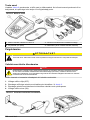
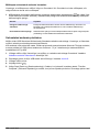
Product components
Refer to Figure 2 to make sure that all components have been received. If any items are missing or
damaged, contact the manufacturer or a sales representative immediately.
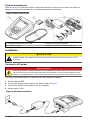
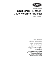
Figure 2 Meter components
1 HQ440d, HQ430d or HQ411d meter 3 AC/DC power supply with cable
2 AA batteries (pk/4) 4 USB cable (HQ440d, HQ430d models only)
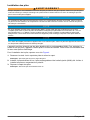
Installation
C A U T I O N
Multiple hazards. Only qualified personnel must conduct the tasks described in this section of the
document.
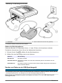
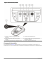
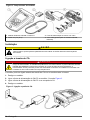
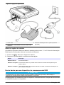
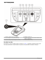
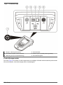
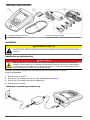
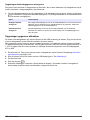
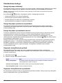
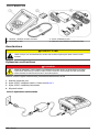
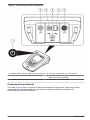
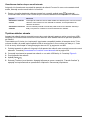
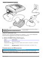
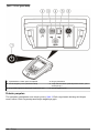
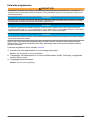
Connect to AC power
D A N G E R
Electrocution Hazard. AC power outlets in wet or potentially wet locations MUST ALWAYS be provided
with a Ground Fault Circuit Interrupting (GFCI/GFI) circuit breaker. The AC-DC power adapter for this
product is not sealed and must not be used on wet benches or in wet locations without GFCI protection.
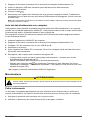
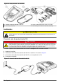
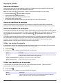
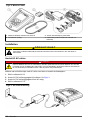
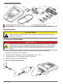
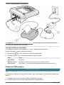
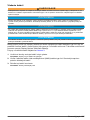
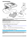
The meter can be powered by AC power with the universal power adapter.
1. Set the meter to OFF.
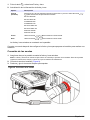
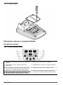
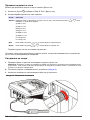
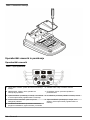
2. Connect the AC/DC power supply to the meter. Refer to Figure 3.
3. Connect the AC/DC power supply to an AC receptacle.
4. Set the meter to ON.
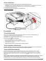
Figure 3 AC power connection
6 English

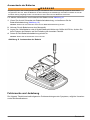
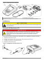
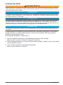
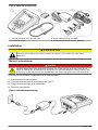
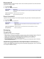
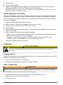
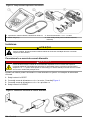
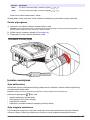
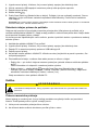
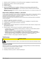
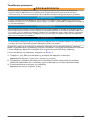
Install the batteries
W A R N I N G
Explosion hazard. Incorrect battery installation can cause the release of explosive gases. Be sure that the
batteries are of the same approved chemical type and are inserted in the correct orientation. Do not mix new and
used batteries.
N O T I C E
The battery compartment is not waterproof. If the battery compartment becomes wet, remove and dry the
batteries and dry the interior of the compartment. Check the battery contacts for corrosion and clean them if
necessary.
N O T I C E
When using nickel metal hydride (NiMH) batteries, the battery icon will not indicate a full charge after freshly
charged batteries have been inserted (NiMH batteries are 1.2 V versus 1.5 V for alkaline batteries). Even though
the icon does not indicate complete charge, 2300 mAH NiMH batteries will achieve 90% of instrument operation
lifetime (before recharge) versus new alkaline batteries.
N O T I C E
To avoid potential damage to the meter from battery leakage, remove the meter batteries prior to extended
periods of non-use.
The meter can be powered with AA alkaline or rechargeable NiMH batteries. To conserve battery life,
the meter will power off after 5 minutes of inactivity. This time can be changed in the Display Options
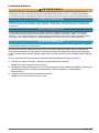
menu.
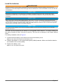
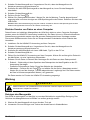
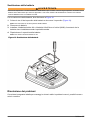
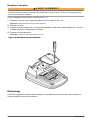
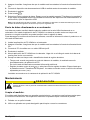
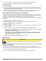
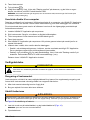
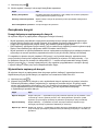
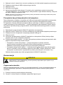
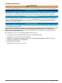
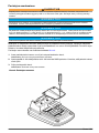
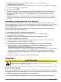
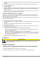
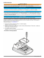
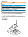
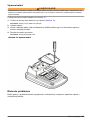
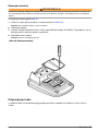
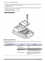
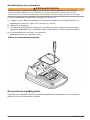
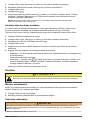
For battery installation refer to Figure 4.
1. Loosen the three battery cover screws and remove the battery cover.
Note: Do not remove the screws from the battery cover.
2. Install 4 AA alkaline or 4 AA nickel metal hydride (NiMH) batteries. Make sure that the batteries
are installed in the correct polarity.
3. Replace the battery cover.
Note: Do not over-tighten the screws.
English
7

Figure 4 Battery installation
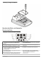
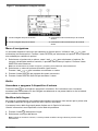
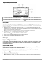
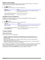
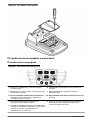
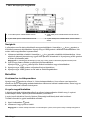
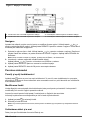
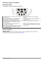
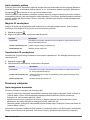
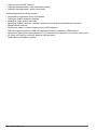
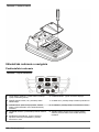
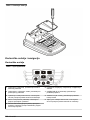
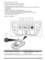
User interface and navigation
User interface
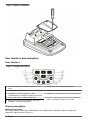
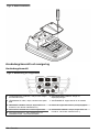
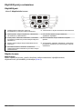
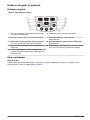
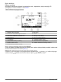
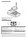
Figure 5 Keypad description
1 LEFT key: calibrates, cancels or exits the current
menu
6 BACKLIGHT: turn off display illumination
2 RIGHT key: reads, selects, confirms or stores data 7 OPERATOR ID: associate data with an individual
3 DOWN key: scroll through menus, enter
numbers/letters or change the reading screen view
8 SAMPLE ID: associate data with a sample location
4 DATA LOG: recall or transfer stored data 9 UP key: scroll through menus, enter numbers and
letters or change the reading screen view
5 METER OPTIONS: change settings, run check
standards, view meter information
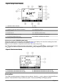
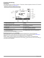
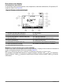
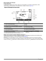
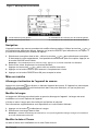
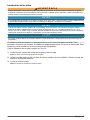
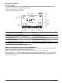
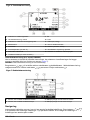
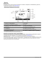
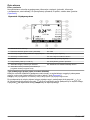
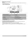
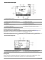
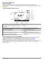
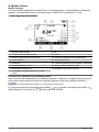
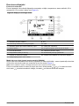
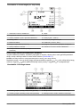
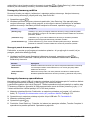
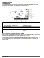
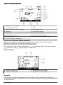
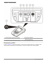
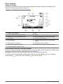
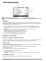
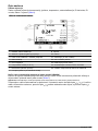
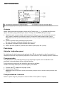
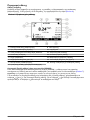
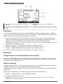
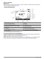
Display description
Measurement screen
The meter display shows the concentration, units, temperature, calibration status, operator ID,
sample ID, date and time (Figure 6).
8
English

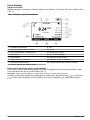
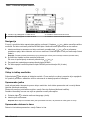
Figure 6 Single screen display
1 Calibration status indicator 9 Time
2 Main measurement value and unit 10 Date
3 IntelliCAL probe type and port indicator 11 Read (OK, Select)
4 Battery status 12 Display size icon
5 Power source 13 Calibrate (Cancel, Exit)
6 Sample temperature (ºC or ºF) 14 Sample and operator identification
7 Secondary measurement unit 15 Stability or display lock indicator
8 Tertiary units (for some probes)
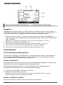
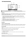
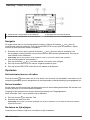
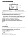
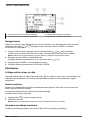
Dual-screen mode (HQ440d model only)
When two probes are connected to the HQ440d meter, the display can show the reading from both
probes simultaneously or show just one probe (Figure 7).
Note: For probe calibration, change the screen mode to the single screen mode.
To change the screen mode to single or dual screen, use the and keys. In dual screen mode,
the key will select the probe on the left and the key will select the probe on the right.
Figure 7 Dual-screen display
1 Probe that is connected to port on left 3 Measurement information for probe on left
2 Probe that is connected to port on right 4 Measurement information for probe on right
Navigation
The meter contains menus to change various options. Use the
and keys to highlight different
options. Push the RIGHT key to select an option. There are two ways to change options:
English
9

1. Select an option from a list: Use the and keys to select an option. If check boxes are
shown, more than one option can be selected. Push the LEFT key under Select.
Note: To deselect check boxes, push the LEFT key under Deselect.
2. Enter an option value using the arrow keys:
Push the and keys to enter or change a value.
3. Push the RIGHT key to advance to the next space.
4. Push the RIGHT key under OK to accept the value.
Startup
Turn the meter on and off
Push the key to turn on or turn off the meter. If the meter does not turn on, make sure that the AC
power supply is properly connected to an electrical outlet or that the batteries are properly installed.
Change the language
The display language is selected when the meter is powered on for the first time. The language can
also be changed from the Meter Options menu.
Access to the language menu can be restricted with the Security Options.
Additional information is available on the manufacturer's website.
1. Push the key and select Language.
2. Select a language from the list.
Note: While turning the meter on, the language can also be changed when the power key is pushed and held.
Change the date and time
The date and time can be changed from the Date & Time menu.
1. Push the key and select Date & Time.
2. Update the time and date information:
Option Description
Format Select one of the formats below for the date and time. Use the and keys to select from the
format options.
dd-mm-yyyy 24h
dd-mm-yyyy 12h
mm/dd/yyyy 24h
mm/dd/yyyy 12h
dd-mmm-yyyy 24h
dd-mmm-yyyy 12h
yyyy-mm-dd 24h
yyyy-mm-dd 12h
Date Use the and keys to enter the current date.
Time Use the and keys to enter the current time.
The current date and time will be shown on the display.
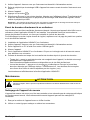
Connect a probe after the date and time setup, so that the meter is ready to take a measurement.
10
English

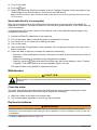
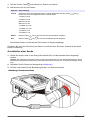
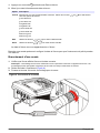
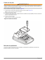
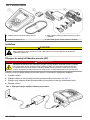
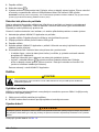
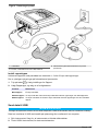
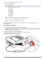
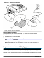
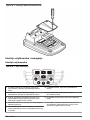
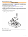
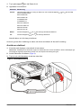
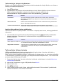
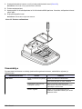
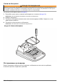
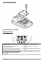
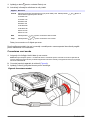
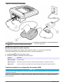
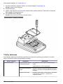
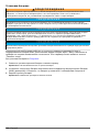
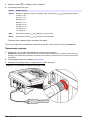
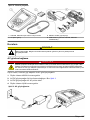
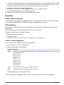
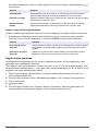
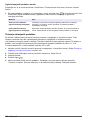
Connect a probe
1. Make sure that the display shows the current time and date.
Note: The time stamp for a probe is set when the probe is first connected to the meter. This time stamp makes
it possible to record the probe history and record the time when measurements are made.
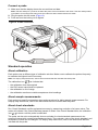
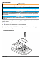
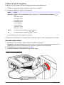
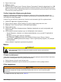
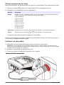
2. Plug the probe into the meter (Figure 8).
3. Push and turn the locking nut to tighten.
Figure 8 Probe connection
Standard operation
About calibration
Each probe uses a different type of calibration solution. Make sure to calibrate the probes frequently
to maintain the highest level of accuracy.
Note: For step-by-step instructions, refer to the documents that are included with each probe.
The calibration icon
can indicate that:
• the calibration timer has expired
• the LDO sensor cap should be replaced
• the calibration is out of range
• the calibration results are outside acceptance criteria settings
About sample measurements
Each probe has specific preparation steps and procedures for taking sample measurements. For
step-by-step instructions, refer to the documents that are included with the probe.
About check standards
Run Check Standards verifies equipment accuracy by measuring a solution of a known value. The
meter will indicate if the Check Standard passed or failed. If the Check Standard fails, the calibration
icon
is shown until the probe is calibrated.
The meter can be set to automatically show a reminder for check standard measurement at a
specified interval with a specified acceptance criteria. The reminder, value of the check standard, and
acceptance criteria can be changed. For step-by-step instructions, refer to the documents that are
included with the probe.
English
11

Use a sample ID
The sample ID tag is used to associate measurements with a particular sample location. If assigned,
stored data will include the sample ID.
1. Push the key.
2. Select, create or delete a sample ID:
Option Description
Current ID Select an ID from a list. The current ID will be associated with sample data until a
different ID is selected.
Create a New Sample ID Enter a name for a new sample ID.
Delete Sample ID Delete an existing sample ID.
Use an operator ID
The operator ID tag associates measurements with an individual operator. All stored data will include
the operator ID.
1. Push the key.
2. Select, create or delete an operator ID:
Option Description
Current ID Select an ID from a list. The current ID will be associated with sample data until
a different ID is selected.
Create a New Operator ID Enter a name for a new operator ID (maximum 10 names can be entered).
Delete Operator ID Delete an existing operator ID.
Data management
About stored data
The following types of data are stored in the data log:
• Sample measurements: stored automatically each time a sample is measured in the Press to
Read or Interval Mode. When the continuous measurement mode is used, data is stored only
when Store is selected.
• Calibrations: stored only when Store is selected at the end of a calibration. Calibration data is also
stored in the IntelliCAL (R) probe.
• Check standard measurements: stored automatically each time a check standard is measured (in
the Press to Read or Interval Mode).
When the data log becomes full (500 data points), the oldest data point is deleted when a new data
point is added. The entire data log can be deleted to remove data that has already been sent to a
printer or PC (
key > Delete Data Log). To prevent deletion of the data log by a user, use the
Security Options menu.
12
English

View stored data
The data log contains sample, calibration and check standard data. The most recent data point in the
data log is tagged as Data Point 001.
1. Push the key.
2. Select View Data Log to view the stored data. The most recent data point is shown. The top of
the screen shows whether the data is from a sample reading, a calibration or a check standard.
Push the key to view the next most recent data point.
Option Description
Reading Log Reading Log—shows sample measurements including the time, date, operator and
sample ID. Select Details to view the associated calibration data.
Calibration Log Calibration Log—shows calibration data. Select Details to view additional information
about the calibration.
Check Standard Log Check Standard Log—shows check standard measurements. Select Details to view
the calibration data that was associated with the measurement.
View stored probe data
Make sure that a probe is connected to the meter. If two probes are connected, select the
appropriate probe when prompted.
1. To view the calibration data that is stored in a probe, push the key and select View Probe
Data. The current calibration and calibration history for the probe can be viewed.
Option Description
View Current
Calibration
The current calibration information shows the calibration details for the most recent
calibration. If the probe has not been calibrated by the user, the factory calibration
data is shown.
View Calibration
History
The calibration history shows a list of the times when the probe was calibrated.
Select a date and time to view a summary of the calibration data.
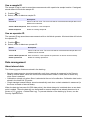
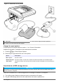
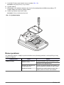
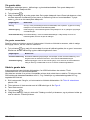
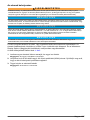
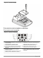
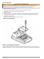
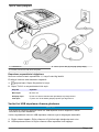
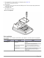
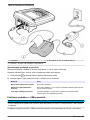
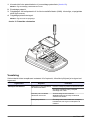
Print stored data
The meter must connect to AC power to start the USB connection. Make sure that the connection to
AC power is made before the meter is powered on.
All data can be sent to a printer. Compatible printers should support a minimum of 72 columns of
data, be capable of printing up to 500 continuous data-stream events in 1, 2 and 3 lines of text and
fully support code page 437 and code page 850.
1. Turn off the meter. Make sure that the meter is connected to AC power. Refer to Connect to AC
power on page 6.
2. Connect the printer to the meter with a USB cable type A. Refer to Figure 9.
3. Turn on the meter.
4. Push the key.
5. Select Send Data Log. Wait for the display to show “Transfer Complete” and wait for the printer to
stop printing. Disconnect the printer.
English
13

Figure 9 Connection to the printer
1 USB cable 3 AC-DC power supply for printer (optional)
2 Printer, FCC Part 15B, Class B compliant
Change the report options
Printed reports for sample data can contain 1, 2 or 3 lines of information.
Additional information is available on the manufacturer's website.
1. Push the key. Select Report Options.
2. Select Report Type and select one of the options.
Option Description
Basic report One line of data.
Advanced report Two lines of data. The first line contains the same information as in the basic report.
Total report Three lines of data. The first two lines contain the same information as in the advanced
report.
Send data to a USB storage device
N O T I C E
The transfer of a large number of data points will take some time. DO NOT disconnect the USB storage device
until the transfer is complete.
Data can be transferred to a USB storage device for storage or transfer to a computer.
1. Turn off the meter. Make sure that the meter is connected to AC power.
2. Plug the USB storage device into the meter before the meter is powered on.
14
English

3. Turn on the meter.
4. Push the key.
5. Select Send Data Log. Wait for the display to show “Transfer Complete” and for any lights on the
USB storage device to stop flashing. Then remove the USB device.
Note: If the data transfer is slow, reformat the USB storage device to use the file allocation table (FAT) format
for the next use.
Send data directly to a computer
Data can be transferred from any HQd series meter directly to a computer when the HQ40d PC
Application is installed. The data can be sent in real time during data collection, or the entire data log
can be transferred.
To download the most current version of the software, refer to the applicable product page on the
manufacturer's website.
1. Install the HQ40d PC Application on the computer.
2. Turn off the meter. Make sure that the meter is connected to AC power.
3. Connect the PC to the meter with a USB type B cable.
4. Turn on the meter.
5. Open the HQ40d PC Application on the computer. Click on the green triangle in the menu bar to
start a connection.
6. Collect the data in real time or transfer the data from the data log:
• Real time—when a data point is stored in the meter, the result is sent simultaneously to the PC
Application.
Additional information is available on the manufacturer's website.
• Data log—push the key and select Send Data Log. Wait for the display to show “Transfer
Complete.” The data is sent as a comma separated values (.csv) file.
The data is shown in the HQ40d PC Application window.
Maintenance
C A U T I O N
Multiple hazards. Only qualified personnel must conduct the tasks described in this section of the
document.
Clean the meter
The meter is designed to be maintenance-free and does not require regular cleaning for normal
operation. Exterior surfaces of the meter may be cleaned as necessary.
1. Wipe the surface of the meter with a damp cloth.
2. Use a cotton-tipped applicator to clean or dry the connectors.
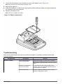
Replace the batteries
W A R N I N G
Explosion hazard. Incorrect battery installation can cause the release of explosive gases. Be sure that the
batteries are of the same approved chemical type and are inserted in the correct orientation. Do not mix new and
used batteries.
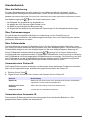
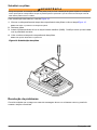
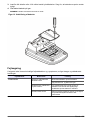
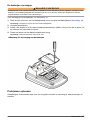
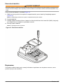
For battery replacement, refer to Figure 10.
English
15

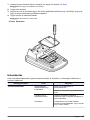
1. Loosen the three battery cover screws and remove the battery cover (Figure 10).
Note: Do not remove the screws from the battery cover.
2. Remove the batteries.
3. Install 4 AA alkaline or 4 AA nickel metal hydride (NiMH) batteries. Make sure that the batteries
are installed in the correct polarity.
4. Replace the battery cover.
Note: Do not over-tighten the screws.
Figure 10 Battery replacement
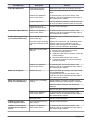
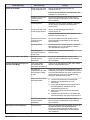
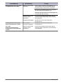
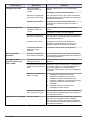
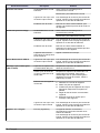
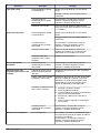
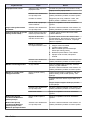
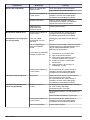
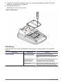
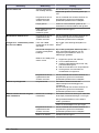
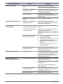
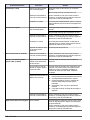
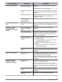
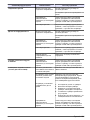
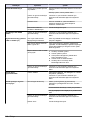
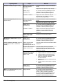
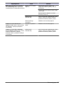
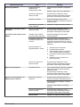
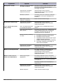
Troubleshooting
Refer to the following table for common problem messages or symptoms, possible causes and
corrective actions.
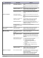
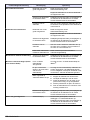
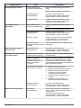
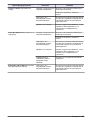
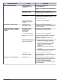
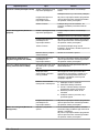
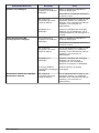
Error/Warning Description Solution
Connect a Probe Probe disconnected or
connected improperly
Tighten the locking nut on the probe connector.
Disconnect the probe and then connect the probe
again
Software not updated to
most current version
To download the most current version of the
software, refer to the applicable product page on
the manufacturer's website.
Problem with probe Connect a different IntelliCAL probe to verify if
problem is with probe or meter
16 English

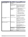
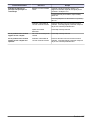
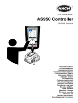
Error/Warning Description Solution
Probe Not Supported Probe disconnected or
connected improperly
Tighten the locking nut on the probe connector.
Disconnect the probe and then connect the probe
again.
Software not updated to
most current version
To download the most current version of the
software, refer to the applicable product page on
the manufacturer's website.
Problem with probe Connect a different IntelliCAL probe to the meter
to verify if problem is with the meter or the probe.
HQd meter does not
support IntelliCAL probe
Contact Technical Support.
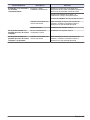
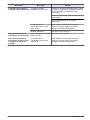
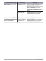
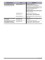
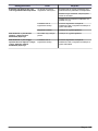
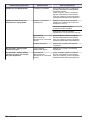
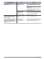
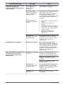
Bootloader X.X.XX.XX error Software not updated to
most current version.
To download the most current version of the
software, refer to the applicable product page on
the manufacturer's website.
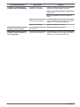
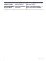
0 days remaining message
(For LDO and LBOD only)
LDO or LBOD sensor cap
used for 365 days
Replace the LDO or LBOD sensor cap and
iButton
®
.
There are 0 days remaining
in the life of the LDO sensor
cap.
Replace the LDO sensor cap. Calibration will be
allowed. However, the calibration icon and
question mark will appear on the measurement
screen even if the calibration has passed.
Meter set to incorrect date
and time
1. Disconnect the probe from the meter.
2. Remove the meter batteries.
3. Install the meter batteries properly. Follow the
polarity makings.
4. Set correct date and time in the meter.
5. Connect the probe and verify that message
has been removed.
Software not updated to
most current version
To download the most current version of the
software, refer to the applicable product page on
the manufacturer's website.
Meter not configured Software error(s) If the meter starts up correctly, back up the Data
Log and Method files.
To download the most current version of the
software, refer to the applicable product page on
the manufacturer's website.
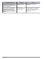
Meter will not power on or
powers on intermittently
Batteries are not installed
correctly
Examine battery orientation to make sure the
batteries follow the polarity markings. Test again.
Clean the battery terminals, then install new
batteries.
Connect AC power adapter and test again.
Software not updated to
most current version
To download the most current version of the
software, refer to the applicable product page on
the manufacturer's website.
Damaged meter Contact Technical Support.
Unable to access Full
Access Options screen
Correct password has not
been entered
Contact Technical Support.
Unable to access Full or
Operator Access Options
screen
Software not updated to
most current version
To download the most current version of the
software, refer to the applicable product page on
the manufacturer's website.
English 17

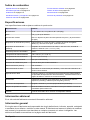
Inhaltsverzeichnis
Technische Daten auf Seite 18
Allgemeine Informationen auf Seite 18
Installation auf Seite 22
Benutzeroberfläche und Navigation auf Seite 24
Inbetriebnahme auf Seite 26
Standardbetrieb auf Seite 28
Datenmanagement auf Seite 29
Wartung auf Seite 32
Fehlersuche und -behebung auf Seite 33
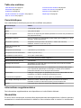
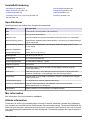
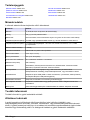
Technische Daten
Änderungen vorbehalten.
Technische Daten Details
Abmessungen 17,48 x 8,59 x 23,5 cm (6.88 x 3.38 x 9.25 Zoll)
Gewicht 750 g (1.65 lb) ohne Batterien
Gerätegehäuse IP54 mit angebrachter Batteriefachabdeckung (staub- und
spritzwassergeschützt)
Spannungsversorgung (intern) Alkalibatterien oder aufladbare Nickelmetallhydrid-Akkus (NiMH) (4 St.);
Batteriestandzeit: bis 200 Stunden
Spannungsversorgung (extern) Externer Netzadapter gemäß Klasse II: 100 bis 240 VAC, Eingang: 50/60 Hz,
Ausgang: 4,5 bis 7,5 VDC (7 VA)
Schutzklasse des Messgerätes Klasse I
Lagertemperatur – 20 bis +60°C
Betriebstemperatur 5 bis 45 °C (41 bis 113 °F)
Luftfeuchtigkeit bei Betrieb maximal 90% (nicht-kondensierend)
5-poliger Eingangsstecker M12-Steckverbinder für IntelliCAL
™
-Sonden
Datenspeicher (intern) 500 Ergebnisse
Datenspeicher Automatisch bei manueller Messung und bei Intervallmessung, manuell bei
kontinuierlicher Messung.
Datenexport USB-Anschluss zum PC bzw. zu einem USB-Speichergerät (beschränkt auf die
Kapazität des Speichergerätes). Übertragen wird der gesamte Datenspeicher
oder die aktuellen Daten bei der Messung.
Anschlüsse Integrierter USB-Anschluss A (für USB 2.0-Flash-Speichergerät, Drucker,
Tastatur) und integrierter USB-Anschluss B (für PC)
Temperaturkorrektur Aus, automatisch und manuell (parameterabhängig)
Sperren der Messanzeige Kontinuierliche Messung, Intervallmessung oder manuelle Messung.
Mittelwertfunktion für LDO-Sonden.
Tastatur Anschluss einer externen PC-Tastatur über USB/DC-Adapter
Zusätzliche Informationen
Zusätzliche Informationen finden Sie auf der Website des Herstellers.
Allgemeine Informationen
Der Hersteller ist nicht verantwortlich für direkte, indirekte, versehentliche oder Folgeschäden, die
aus Fehlern oder Unterlassungen in diesem Handbuch entstanden. Der Hersteller behält sich
jederzeit und ohne vorherige Ankündigung oder Verpflichtung das Recht auf Verbesserungen an
18
Deutsch

diesem Handbuch und den hierin beschriebenen Produkten vor. Überarbeitete Ausgaben der
Bedienungsanleitung sind auf der Hersteller-Webseite erhältlich.
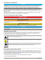
Sicherheitshinweise
H I N W E I S
Der Hersteller ist nicht für Schäden verantwortlich, die durch Fehlanwendung oder Missbrauch dieses Produkts
entstehen, einschließlich, aber ohne Beschränkung auf direkte, zufällige oder Folgeschäden, und lehnt jegliche
Haftung im gesetzlich zulässigen Umfang ab. Der Benutzer ist selbst dafür verantwortlich, schwerwiegende
Anwendungsrisiken zu erkennen und erforderliche Maßnahmen durchzuführen, um die Prozesse im Fall von
möglichen Gerätefehlern zu schützen.
Bitte lesen Sie dieses Handbuch komplett durch, bevor Sie dieses Gerät auspacken, aufstellen oder
bedienen. Beachten Sie alle Gefahren- und Warnhinweise. Nichtbeachtung kann zu schweren
Verletzungen des Bedieners oder Schäden am Gerät führen.
Stellen Sie sicher, dass die durch dieses Messgerät bereitgestellte Sicherheit nicht beeinträchtigt
wird. Verwenden bzw. installieren Sie das Messsystem nur wie in diesem Handbuch beschrieben.
Bedeutung von Gefahrenhinweisen
G E F A H R
Kennzeichnet eine mögliche oder drohende Gefahrensituation, die, wenn sie nicht vermieden wird, zum Tod oder
zu schweren Verletzungen führt.
W A R N U N G
Kennzeichnet eine mögliche oder drohende Gefahrensituation, die, wenn sie nicht vermieden wird, zum Tod oder
zu schweren Verletzungen führen kann.
V O R S I C H T
Kennzeichnet eine mögliche Gefahrensituation, die zu geringeren oder moderaten Verletzungen führen kann.
H I N W E I S
Kennzeichnet eine Situation, die, wenn sie nicht vermieden wird, das Gerät beschädigen kann. Informationen, die
besonders beachtet werden müssen.
Warnhinweise
Lesen Sie alle am Gerät angebrachten Aufkleber und Hinweise. Nichtbeachtung kann Verletzungen
oder Beschädigungen des Geräts zur Folge haben. Im Handbuch werden auf die am Gerät
angebrachten Symbole in Form von Warnhinweisen verwiesen.
Dieses Symbol am Gerät weist auf Betriebs- und/oder Sicherheitsinformationen im Handbuch hin.
Dieses Symbol gibt an, dass die bezeichnete Stelle heiß werden kann und deswegen ohne
entsprechende Schutzvorkehrungen nicht berührt werden sollte.
Elektrogeräte, die mit diesem Symbol gekennzeichnet sind, dürfen nicht im normalen öffentlichen
Abfallsystem entsorgt werden. Senden Sie Altgeräte an den Hersteller zurück. Dieser entsorgt die
Geräte ohne Kosten für den Benutzer.
Produktübersicht
Die Labormessgeräte der Baureihe HQd werden in Verbindung mit den IntelliCAL
™
-Digitalsonden
zur Messung verschiedener Parameter im Wasser eingesetzt. Das Messgerät erkennt automatisch
Deutsch
19

die Art der angeschlossenen Sonde. Messwertdaten können gespeichert und an einen Drucker,
einen PC oder ein USB-Speichergerät übertragen werden (siehe Abbildung 1).
Die Baureihe HQd besteht aus drei Gerätemodellen:
• HQ411d – pH/mV/ORP (Redox)
• HQ430d – mehrere Parameter, ein Sondereingang
• HQ440d – mehrere Parameter, zwei Sondeneingänge
Gemeinsame Merkmale aller Modelle
• Automatische Sonden- und Parametererkennung
• Menügesteuerte Kalibrierung
• In der Sonde gespeicherte Kalibrierungsdaten
• Sondenspezifische Verfahrenseinstellungen zur Einhaltung gesetzlicher Vorschriften und
allgemein anerkannter Arbeitsabläufe im Labor
• Sicherheitsoptionen
• Echtzeit-Datenprotokollierung über eine USB-Verbindung
• USB-Anschluss für PC/Drucker/USB-Speichergerät/Tastatur
• Bidirektionale Kommunikation mit PC-Systemen über eine virtuelle serielle Verbindung
• Proben-ID und Bediener-ID sorgen zur Rückführbarkeit der Daten
• Einstellbare automatische Abschaltung
20 Deutsch
Pagina se încarcă...
Pagina se încarcă...
Pagina se încarcă...
Pagina se încarcă...
Pagina se încarcă...
Pagina se încarcă...
Pagina se încarcă...
Pagina se încarcă...
Pagina se încarcă...
Pagina se încarcă...
Pagina se încarcă...
Pagina se încarcă...
Pagina se încarcă...
Pagina se încarcă...
Pagina se încarcă...
Pagina se încarcă...
Pagina se încarcă...
Pagina se încarcă...
Pagina se încarcă...
Pagina se încarcă...
Pagina se încarcă...
Pagina se încarcă...
Pagina se încarcă...
Pagina se încarcă...
Pagina se încarcă...
Pagina se încarcă...
Pagina se încarcă...
Pagina se încarcă...
Pagina se încarcă...
Pagina se încarcă...
Pagina se încarcă...
Pagina se încarcă...
Pagina se încarcă...
Pagina se încarcă...
Pagina se încarcă...
Pagina se încarcă...
Pagina se încarcă...
Pagina se încarcă...
Pagina se încarcă...
Pagina se încarcă...
Pagina se încarcă...
Pagina se încarcă...
Pagina se încarcă...
Pagina se încarcă...
Pagina se încarcă...
Pagina se încarcă...
Pagina se încarcă...
Pagina se încarcă...
Pagina se încarcă...
Pagina se încarcă...
Pagina se încarcă...
Pagina se încarcă...
Pagina se încarcă...
Pagina se încarcă...
Pagina se încarcă...
Pagina se încarcă...
Pagina se încarcă...
Pagina se încarcă...
Pagina se încarcă...
Pagina se încarcă...
Pagina se încarcă...
Pagina se încarcă...
Pagina se încarcă...
Pagina se încarcă...
Pagina se încarcă...
Pagina se încarcă...
Pagina se încarcă...
Pagina se încarcă...
Pagina se încarcă...
Pagina se încarcă...
Pagina se încarcă...
Pagina se încarcă...
Pagina se încarcă...
Pagina se încarcă...
Pagina se încarcă...
Pagina se încarcă...
Pagina se încarcă...
Pagina se încarcă...
Pagina se încarcă...
Pagina se încarcă...
Pagina se încarcă...
Pagina se încarcă...
Pagina se încarcă...
Pagina se încarcă...
Pagina se încarcă...
Pagina se încarcă...
Pagina se încarcă...
Pagina se încarcă...
Pagina se încarcă...
Pagina se încarcă...
Pagina se încarcă...
Pagina se încarcă...
Pagina se încarcă...
Pagina se încarcă...
Pagina se încarcă...
Pagina se încarcă...
Pagina se încarcă...
Pagina se încarcă...
Pagina se încarcă...
Pagina se încarcă...
Pagina se încarcă...
Pagina se încarcă...
Pagina se încarcă...
Pagina se încarcă...
Pagina se încarcă...
Pagina se încarcă...
Pagina se încarcă...
Pagina se încarcă...
Pagina se încarcă...
Pagina se încarcă...
Pagina se încarcă...
Pagina se încarcă...
Pagina se încarcă...
Pagina se încarcă...
Pagina se încarcă...
Pagina se încarcă...
Pagina se încarcă...
Pagina se încarcă...
Pagina se încarcă...
Pagina se încarcă...
Pagina se încarcă...
Pagina se încarcă...
Pagina se încarcă...
Pagina se încarcă...
Pagina se încarcă...
Pagina se încarcă...
Pagina se încarcă...
Pagina se încarcă...
Pagina se încarcă...
Pagina se încarcă...
Pagina se încarcă...
Pagina se încarcă...
Pagina se încarcă...
Pagina se încarcă...
Pagina se încarcă...
Pagina se încarcă...
Pagina se încarcă...
Pagina se încarcă...
Pagina se încarcă...
Pagina se încarcă...
Pagina se încarcă...
Pagina se încarcă...
Pagina se încarcă...
Pagina se încarcă...
Pagina se încarcă...
Pagina se încarcă...
Pagina se încarcă...
Pagina se încarcă...
Pagina se încarcă...
Pagina se încarcă...
Pagina se încarcă...
Pagina se încarcă...
Pagina se încarcă...
Pagina se încarcă...
Pagina se încarcă...
Pagina se încarcă...
Pagina se încarcă...
Pagina se încarcă...
Pagina se încarcă...
Pagina se încarcă...
Pagina se încarcă...
Pagina se încarcă...
Pagina se încarcă...
Pagina se încarcă...
Pagina se încarcă...
Pagina se încarcă...
Pagina se încarcă...
Pagina se încarcă...
Pagina se încarcă...
Pagina se încarcă...
Pagina se încarcă...
Pagina se încarcă...
Pagina se încarcă...
Pagina se încarcă...
Pagina se încarcă...
Pagina se încarcă...
Pagina se încarcă...
Pagina se încarcă...
Pagina se încarcă...
Pagina se încarcă...
Pagina se încarcă...
Pagina se încarcă...
Pagina se încarcă...
Pagina se încarcă...
Pagina se încarcă...
Pagina se încarcă...
Pagina se încarcă...
Pagina se încarcă...
Pagina se încarcă...
Pagina se încarcă...
Pagina se încarcă...
Pagina se încarcă...
Pagina se încarcă...
Pagina se încarcă...
Pagina se încarcă...
Pagina se încarcă...
Pagina se încarcă...
Pagina se încarcă...
Pagina se încarcă...
Pagina se încarcă...
Pagina se încarcă...
Pagina se încarcă...
Pagina se încarcă...
Pagina se încarcă...
Pagina se încarcă...
Pagina se încarcă...
Pagina se încarcă...
Pagina se încarcă...
Pagina se încarcă...
Pagina se încarcă...
Pagina se încarcă...
Pagina se încarcă...
Pagina se încarcă...
Pagina se încarcă...
Pagina se încarcă...
Pagina se încarcă...
Pagina se încarcă...
Pagina se încarcă...
Pagina se încarcă...
Pagina se încarcă...
Pagina se încarcă...
Pagina se încarcă...
Pagina se încarcă...
Pagina se încarcă...
Pagina se încarcă...
Pagina se încarcă...
Pagina se încarcă...
Pagina se încarcă...
Pagina se încarcă...
Pagina se încarcă...
Pagina se încarcă...
Pagina se încarcă...
Pagina se încarcă...
Pagina se încarcă...
Pagina se încarcă...
Pagina se încarcă...
Pagina se încarcă...
Pagina se încarcă...
Pagina se încarcă...
Pagina se încarcă...
Pagina se încarcă...
Pagina se încarcă...
Pagina se încarcă...
Pagina se încarcă...
Pagina se încarcă...
Pagina se încarcă...
Pagina se încarcă...
Pagina se încarcă...
Pagina se încarcă...
Pagina se încarcă...
Pagina se încarcă...
Pagina se încarcă...
Pagina se încarcă...
Pagina se încarcă...
Pagina se încarcă...
Pagina se încarcă...
Pagina se încarcă...
Pagina se încarcă...
Pagina se încarcă...
Pagina se încarcă...
Pagina se încarcă...
Pagina se încarcă...
Pagina se încarcă...
Pagina se încarcă...
Pagina se încarcă...
Pagina se încarcă...
Pagina se încarcă...
Pagina se încarcă...
Pagina se încarcă...
Pagina se încarcă...
Pagina se încarcă...
Pagina se încarcă...
Pagina se încarcă...
Pagina se încarcă...
Pagina se încarcă...
Pagina se încarcă...
Pagina se încarcă...
Pagina se încarcă...
Pagina se încarcă...
Pagina se încarcă...
Pagina se încarcă...
Pagina se încarcă...
Pagina se încarcă...
Pagina se încarcă...
Pagina se încarcă...
Pagina se încarcă...
Pagina se încarcă...
Pagina se încarcă...
Pagina se încarcă...
Pagina se încarcă...
Pagina se încarcă...
Pagina se încarcă...
Pagina se încarcă...
Pagina se încarcă...
Pagina se încarcă...
Pagina se încarcă...
Pagina se încarcă...
Pagina se încarcă...
Pagina se încarcă...
Pagina se încarcă...
Pagina se încarcă...
Pagina se încarcă...
Pagina se încarcă...
Pagina se încarcă...
Pagina se încarcă...
Pagina se încarcă...
Pagina se încarcă...
Pagina se încarcă...
Pagina se încarcă...
Pagina se încarcă...
Pagina se încarcă...
Pagina se încarcă...
Pagina se încarcă...
Pagina se încarcă...
Pagina se încarcă...
Pagina se încarcă...
Pagina se încarcă...
Pagina se încarcă...
Pagina se încarcă...
Pagina se încarcă...
Pagina se încarcă...
Pagina se încarcă...
Pagina se încarcă...
Pagina se încarcă...
Pagina se încarcă...
Pagina se încarcă...
Pagina se încarcă...
Pagina se încarcă...
Pagina se încarcă...
Pagina se încarcă...
Pagina se încarcă...
Pagina se încarcă...
Pagina se încarcă...
Pagina se încarcă...
Pagina se încarcă...
Pagina se încarcă...
Pagina se încarcă...
Pagina se încarcă...
Pagina se încarcă...
Pagina se încarcă...
Pagina se încarcă...
Pagina se încarcă...
Pagina se încarcă...
Pagina se încarcă...
Pagina se încarcă...
Pagina se încarcă...
Pagina se încarcă...
Pagina se încarcă...
Pagina se încarcă...
Pagina se încarcă...
Pagina se încarcă...
Pagina se încarcă...
Pagina se încarcă...
Pagina se încarcă...
Pagina se încarcă...
Pagina se încarcă...
Pagina se încarcă...
Pagina se încarcă...
Pagina se încarcă...
Pagina se încarcă...
Pagina se încarcă...
Pagina se încarcă...
Pagina se încarcă...
Pagina se încarcă...
Pagina se încarcă...
Pagina se încarcă...
Pagina se încarcă...
Pagina se încarcă...
Pagina se încarcă...
Pagina se încarcă...
Pagina se încarcă...
Pagina se încarcă...
Pagina se încarcă...
Pagina se încarcă...
Pagina se încarcă...
Pagina se încarcă...
Pagina se încarcă...
Pagina se încarcă...
Pagina se încarcă...
Pagina se încarcă...
Pagina se încarcă...
Pagina se încarcă...
Pagina se încarcă...
Pagina se încarcă...
Pagina se încarcă...
Pagina se încarcă...
Pagina se încarcă...
Pagina se încarcă...
Pagina se încarcă...
Pagina se încarcă...
Pagina se încarcă...
Pagina se încarcă...
-
 1
1
-
 2
2
-
 3
3
-
 4
4
-
 5
5
-
 6
6
-
 7
7
-
 8
8
-
 9
9
-
 10
10
-
 11
11
-
 12
12
-
 13
13
-
 14
14
-
 15
15
-
 16
16
-
 17
17
-
 18
18
-
 19
19
-
 20
20
-
 21
21
-
 22
22
-
 23
23
-
 24
24
-
 25
25
-
 26
26
-
 27
27
-
 28
28
-
 29
29
-
 30
30
-
 31
31
-
 32
32
-
 33
33
-
 34
34
-
 35
35
-
 36
36
-
 37
37
-
 38
38
-
 39
39
-
 40
40
-
 41
41
-
 42
42
-
 43
43
-
 44
44
-
 45
45
-
 46
46
-
 47
47
-
 48
48
-
 49
49
-
 50
50
-
 51
51
-
 52
52
-
 53
53
-
 54
54
-
 55
55
-
 56
56
-
 57
57
-
 58
58
-
 59
59
-
 60
60
-
 61
61
-
 62
62
-
 63
63
-
 64
64
-
 65
65
-
 66
66
-
 67
67
-
 68
68
-
 69
69
-
 70
70
-
 71
71
-
 72
72
-
 73
73
-
 74
74
-
 75
75
-
 76
76
-
 77
77
-
 78
78
-
 79
79
-
 80
80
-
 81
81
-
 82
82
-
 83
83
-
 84
84
-
 85
85
-
 86
86
-
 87
87
-
 88
88
-
 89
89
-
 90
90
-
 91
91
-
 92
92
-
 93
93
-
 94
94
-
 95
95
-
 96
96
-
 97
97
-
 98
98
-
 99
99
-
 100
100
-
 101
101
-
 102
102
-
 103
103
-
 104
104
-
 105
105
-
 106
106
-
 107
107
-
 108
108
-
 109
109
-
 110
110
-
 111
111
-
 112
112
-
 113
113
-
 114
114
-
 115
115
-
 116
116
-
 117
117
-
 118
118
-
 119
119
-
 120
120
-
 121
121
-
 122
122
-
 123
123
-
 124
124
-
 125
125
-
 126
126
-
 127
127
-
 128
128
-
 129
129
-
 130
130
-
 131
131
-
 132
132
-
 133
133
-
 134
134
-
 135
135
-
 136
136
-
 137
137
-
 138
138
-
 139
139
-
 140
140
-
 141
141
-
 142
142
-
 143
143
-
 144
144
-
 145
145
-
 146
146
-
 147
147
-
 148
148
-
 149
149
-
 150
150
-
 151
151
-
 152
152
-
 153
153
-
 154
154
-
 155
155
-
 156
156
-
 157
157
-
 158
158
-
 159
159
-
 160
160
-
 161
161
-
 162
162
-
 163
163
-
 164
164
-
 165
165
-
 166
166
-
 167
167
-
 168
168
-
 169
169
-
 170
170
-
 171
171
-
 172
172
-
 173
173
-
 174
174
-
 175
175
-
 176
176
-
 177
177
-
 178
178
-
 179
179
-
 180
180
-
 181
181
-
 182
182
-
 183
183
-
 184
184
-
 185
185
-
 186
186
-
 187
187
-
 188
188
-
 189
189
-
 190
190
-
 191
191
-
 192
192
-
 193
193
-
 194
194
-
 195
195
-
 196
196
-
 197
197
-
 198
198
-
 199
199
-
 200
200
-
 201
201
-
 202
202
-
 203
203
-
 204
204
-
 205
205
-
 206
206
-
 207
207
-
 208
208
-
 209
209
-
 210
210
-
 211
211
-
 212
212
-
 213
213
-
 214
214
-
 215
215
-
 216
216
-
 217
217
-
 218
218
-
 219
219
-
 220
220
-
 221
221
-
 222
222
-
 223
223
-
 224
224
-
 225
225
-
 226
226
-
 227
227
-
 228
228
-
 229
229
-
 230
230
-
 231
231
-
 232
232
-
 233
233
-
 234
234
-
 235
235
-
 236
236
-
 237
237
-
 238
238
-
 239
239
-
 240
240
-
 241
241
-
 242
242
-
 243
243
-
 244
244
-
 245
245
-
 246
246
-
 247
247
-
 248
248
-
 249
249
-
 250
250
-
 251
251
-
 252
252
-
 253
253
-
 254
254
-
 255
255
-
 256
256
-
 257
257
-
 258
258
-
 259
259
-
 260
260
-
 261
261
-
 262
262
-
 263
263
-
 264
264
-
 265
265
-
 266
266
-
 267
267
-
 268
268
-
 269
269
-
 270
270
-
 271
271
-
 272
272
-
 273
273
-
 274
274
-
 275
275
-
 276
276
-
 277
277
-
 278
278
-
 279
279
-
 280
280
-
 281
281
-
 282
282
-
 283
283
-
 284
284
-
 285
285
-
 286
286
-
 287
287
-
 288
288
-
 289
289
-
 290
290
-
 291
291
-
 292
292
-
 293
293
-
 294
294
-
 295
295
-
 296
296
-
 297
297
-
 298
298
-
 299
299
-
 300
300
-
 301
301
-
 302
302
-
 303
303
-
 304
304
-
 305
305
-
 306
306
-
 307
307
-
 308
308
-
 309
309
-
 310
310
-
 311
311
-
 312
312
-
 313
313
-
 314
314
-
 315
315
-
 316
316
-
 317
317
-
 318
318
-
 319
319
-
 320
320
-
 321
321
-
 322
322
-
 323
323
-
 324
324
-
 325
325
-
 326
326
-
 327
327
-
 328
328
-
 329
329
-
 330
330
-
 331
331
-
 332
332
-
 333
333
-
 334
334
-
 335
335
-
 336
336
-
 337
337
-
 338
338
-
 339
339
-
 340
340
-
 341
341
-
 342
342
-
 343
343
-
 344
344
-
 345
345
-
 346
346
-
 347
347
-
 348
348
-
 349
349
-
 350
350
-
 351
351
-
 352
352
-
 353
353
-
 354
354
-
 355
355
-
 356
356
-
 357
357
-
 358
358
-
 359
359
-
 360
360
-
 361
361
-
 362
362
-
 363
363
-
 364
364
-
 365
365
-
 366
366
-
 367
367
-
 368
368
-
 369
369
-
 370
370
-
 371
371
-
 372
372
-
 373
373
-
 374
374
-
 375
375
-
 376
376
-
 377
377
-
 378
378
-
 379
379
-
 380
380
-
 381
381
-
 382
382
-
 383
383
-
 384
384
-
 385
385
-
 386
386
-
 387
387
-
 388
388
-
 389
389
-
 390
390
-
 391
391
-
 392
392
-
 393
393
-
 394
394
-
 395
395
-
 396
396
-
 397
397
-
 398
398
-
 399
399
-
 400
400
-
 401
401
-
 402
402
-
 403
403
-
 404
404
-
 405
405
-
 406
406
-
 407
407
-
 408
408
-
 409
409
-
 410
410
-
 411
411
-
 412
412


Hach HQ440d Basic User Manual
- Tip
- Basic User Manual
în alte limbi
- slovenčina: Hach HQ440d
- eesti: Hach HQ440d
- português: Hach HQ440d
Lucrări înrudite
-
Hach HQ30d Basic User Manual
-
Hach HQ440d Basic User Manual
-
 Hach AS950 Basic Operations
-
 Hach Lange ORBISPHERE 3100 Basic User Manual
-
 Hach ORBISPHERE 3658 Basic User Manual
-
 Hach TL2310 Basic User Manual
-
 Hach sensION+ DL Manual de utilizare
-
 Hach Lange ORBISPHERE 3100 Basic User Manual
-
Hach TL2350 Basic User Manual
-
Hach sensION+ MM150 Manual de utilizare


