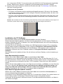
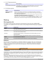
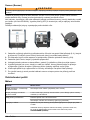
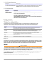
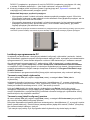
Hach Lange ORBISPHERE 3100 Basic User Manual
- Tip
- Basic User Manual

DOC024.98.93051
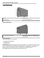
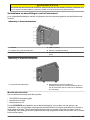
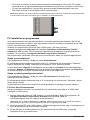
ORBISPHERE Model
3100 Portable Analyzer
06/2012, Edition 4
Basic User Manual
Basis-Bedienungsanleitung
Manuale dell'utente di base
Manuel d'utilisation de base
Manual básico del usuario
Základní uživatelská příručka
Grundlæggende brugervejledning
Basisgebruikershandleiding
Podstawowa instrukcja obsługi
Grundläggande bruksanvisning
Peruskäyttöohje
Основно ръководство за потребителя
Alapvető felhasználói kézikönyv
Manual de bază al utilizatorului
Temel Kullanıcı Kılavuzu
Osnovni korisnički priručnik
Βασικό εγχειρίδιο χρήσης

English..............................................................................................................................3
Deutsch..........................................................................................................................24
Italiano............................................................................................................................47
Français.........................................................................................................................69
Español..........................................................................................................................92
Čeština.........................................................................................................................115
Dansk............................................................................................................................137
Nederlands.................................................................................................................158
Polski............................................................................................................................180
Svenska.......................................................................................................................204
Suomi............................................................................................................................225
български...................................................................................................................246
Magyar.........................................................................................................................270
Română.......................................................................................................................292
Türkçe...........................................................................................................................314
Hrvatski........................................................................................................................336
Ελληνικά......................................................................................................................358
2

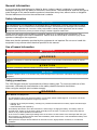
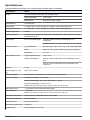
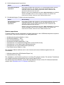
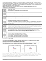
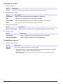
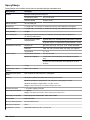
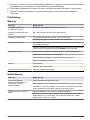
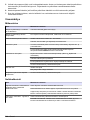
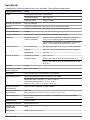
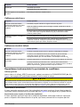
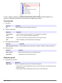
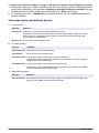
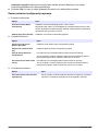
Specifications
Specifications are subject to change without notice
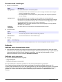
Specification Details
Sample Non-flammable gaseous or liquid samples
Sample temperature -5 to 45°C (23 to 113°F)
Sample pressure 0 to 10 bar (0 to 140 psi)
Measurement range 0 to 2000 ppb
Accuracy ± 0.8 ppb or ± 2% of reading whichever is the greater
Repeatability r95 ± 0.4 ppb or ± 1% of reading whichever is the greater
Detection limits 0.6 ppb
Response time t90 Usually less than 15 seconds but will vary depending on the sampling method
Measurements Holds up to
5,760 measurements
8 hours of data at a sampling frequency of 5 seconds
96 hours of data at a sampling frequency of 1 minute
Display units O
2
concentration ppb, ppm, μg/L, mg/L, mL/L, %O
2
, %air, %Vbar, ppmVbar
Pressure mbar, bar, Pa, hPa, kPa, MPa, psia, psig, atm, kgf/cm2
Temperature °C, °F, K
Operating conditions Ambient temperature -5 to 45°C (23 to 113°F)
Relative humidity 0 to 95% non-condensing for temperatures less than
30°C (86°F)
0 to 70% non-condensing for temperatures from 30 to
45°C (86 to 113°F)
Weight 3.4 kg (7.5 lbs)
Dimensions (L x W x H) 200 x 170 x 190 mm (7.87 x 6.69 x 7.48 ins)
Waterproof protection Stainless steel IP66 with polycarbonate sides
Power supply Internal rechargeable battery pack: Li-Ion 46Wh
External power supply input: 100-240 VAC ±10% @ 47-63 Hz
External power supply output: 12 VDC, 3.75 A
Note: External power supply is not IP66
Battery life > 10 hours of continuous measurement
Battery charge time < 4 hours
Note: Charge time increases by 20% at a temperature above 35°C (95°F)
European directives Low voltage 2006/95/EC, EMC 2004/108/EC
EMC standards EN61326:2006
Safety standard IEC/UL/CSA 61010-1
Overvoltage category Cat II
Digital display TFT color display 72 x 54 mm (2.83 x 2.13 ins)
Digital connections 1 x USB (5 VDC) Input/Output mass storage device
1 x RS232 (0-5 V) Serial output
English 3

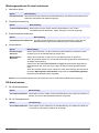
General information
In no event will the manufacturer be liable for direct, indirect, special, incidental or consequential
damages resulting from any defect or omission in this manual. The manufacturer reserves the right to
make changes in this manual and the products it describes at any time, without notice or obligation.
Revised editions are found on the manufacturer’s website.
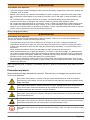
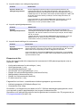
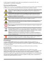
Safety information
N O T I C E
The manufacturer is not responsible for any damages due to misapplication or misuse of this product including,
without limitation, direct, incidental and consequential damages, and disclaims such damages to the full extent
permitted under applicable law. The user is solely responsible to identify critical application risks and install
appropriate mechanisms to protect processes during a possible equipment malfunction.
Please read this entire manual before unpacking, setting up or operating this equipment. Pay
attention to all danger and caution statements. Failure to do so could result in serious injury to the
operator or damage to the equipment.
Make sure that the protection provided by this equipment is not impaired. Do not use or install this
equipment in any manner other than that specified in this manual.
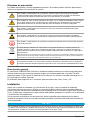
Use of hazard information
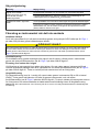
D A N G E R
Indicates a potentially or imminently hazardous situation which, if not avoided, will result in death or serious injury.
W A R N I N G
Indicates a potentially or imminently hazardous situation which, if not avoided, could result in death or serious
injury.
C A U T I O N
Indicates a potentially hazardous situation that may result in minor or moderate injury.
N O T I C E
Indicates a situation which, if not avoided, may cause damage to the instrument. Information that requires special
emphasis.
Safety precautions
The 3100 Oxygen Analyzer is powered with a lithium battery pack. To ensure the safe use of this
instrument, read and pay close attention to the safety related information that follows.
When using the analyzer (also includes storage):
W A R N I N G
Burn Hazard, Fire, Explosion.
• The temperature range over which the battery can be used, stored or discharged is -10 to 60°C. Use of the
battery outside of this temperature range may result in:
• Damage to the analyzer's battery, resulting in a potential fire hazard from a battery rupture and electrolyte
leakage, and
• Reduced battery life expectancy
• Immediately discontinue use of the instrument if, while using or charging the battery, the battery emits an
unusual smell, smoke or the enclosure feels unusually hot to the touch. Contact your Hach Lange Service
Center, if any of these problems are observed.
• In the event of a battery electrolyte leakage from the enclosure, avoid contact of the electrolyte with the eyes.
Do not rub the eye. Rinse well with water and immediately seek medical care. If left untreated the battery fluid
could cause damage to the eye.
• Never place the analyzer and its batteries in microwave ovens, high-pressure containers, or on induction
cookware.
4 English

W A R N I N G
Burn Hazard, Fire, Explosion.
• Use of the analyzer should immediately be discontinued if the battery compartment is exposed to flooding due
to leakage, wear or misuse.
• Misuse of the analyzer may cause the internal battery to get hot, explode, or ignite and cause serious injury.
• Do not expose the internal battery to any liquid such as water, beer or salt water, or allow the battery to get
wet.
• Do not disassemble or modify the analyzer or its battery. The internal battery pack contains safety and
protection devices which, if damaged, may cause the battery to generate heat, explode or ignite.
• Do not place the battery/instrument on or near fires, stoves, or other high temperature locations (above 60°C).
Do not place the battery/instrument in direct sunlight, or use or store the battery inside cars in hot weather.
Doing so may cause the battery to generate heat, explode, or ignite. Using the battery in this manner may also
result in a loss of performance and a shortened life expectancy.
When charging the battery:
W A R N I N G
Burn Hazard, Fire, Explosion.
Be sure to follow the rules listed below while charging the battery. Failure to do so may cause the battery to
become hot, explode, or ignite and cause serious injury.
• The temperature range over which the battery can be charged is 10 to 45°C. Charging the battery at
temperatures outside of this range may cause the battery to become hot or to rupture. Charging the battery
outside of this temperature range may also harm the performance of the battery or reduce the battery's life
expectancy.
• When charging the batteries use the specified battery charger provided with the instrument.
• When charging batteries, do not place the analyzer in or near fire, or into direct sunlight. The additional heat
can result in increased battery heating that can damage the battery's built-in protection circuitry necessary for
prevention of ignition of the battery. Additionally, increased heat may cause activation of the batteries built-in
protection circuitry, thus preventing the battery from charging further.
• Do not continue charging the battery if it does not recharge within the specified charging time. Doing so may
cause the battery to become hot, explode, or ignite. Contact your Hach Lange Service Center, if any charging
problems are observed.
Hach Lange assumes no liability for problems that occur when the precautions listed above are not
followed.
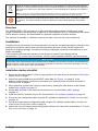
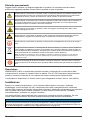
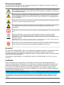
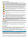
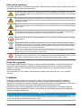
Precautionary labels
Read all labels and tags attached to the product. Personal injury or damage to the product could
occur if not observed.
This symbol, when noted on a product, indicates a potential hazard which could cause serious
personal injury and/or death. The user should reference this instruction manual for operation and/or
safety information.
This symbol, when noted on a product enclosure or barrier, indicates that a risk of electrical shock
and/or electrocution exists and indicates that only individuals qualified to work with hazardous
voltages should open the enclosure or remove the barrier.
This symbol, when noted on the product, indicates that the marked item can be hot and should not
be touched without care.
This symbol, when noted on the product, indicates the presence of devices sensitive to electrostatic
discharge and indicates that care must be taken to prevent damage to them.
This symbol, when noted on the product, identifies the location of the connection for protective earth
(ground).
English 5

Electrical equipment marked with this symbol may not be disposed of in European public disposal
systems. In conformity with European local and national regulations, European electrical equipment
users must now return old or end-of-life equipment to the manufacturer for disposal at no charge to
the user.
Note: For return for recycling, please contact the equipment producer or supplier for instructions on how to return
end-of-life equipment, producer-supplied electrical accessories, and all auxillary items for proper disposal.
Products marked with this symbol indicates that the product contains toxic or hazardous substances
or elements. The number inside the symbol indicates the environmental protection use period in
years.
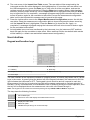
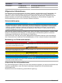
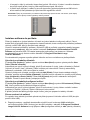
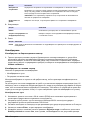
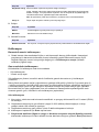
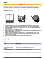
Overview
The ORBISPHERE 3100 instrument is a self-contained portable analyzer, configured to make
oxygen concentration measurements in gaseous or liquid samples. Up to 5,760 measurement values
can be stored in memory and downloaded to a personal computer for further analysis.
The analyzer is available in 3 different versions (for 4mm, 6mm and 1/4 inch connections).
Installation
Carefully remove the analyzer and its accessories from the box and packing material, referring to the
packing list included to confirm that everything has been delivered. Please visually inspect the
analyzer for shipping damage. If anything is missing or damaged, contact the manufacturer or your
dealer immediately.
A thin protective film has been placed over the screen to protect it from damage during
transportation. For a clear view of the screen, this film must be peeled off before using the analyzer.
N O T I C E
A secondary more robust protective film has been factory installed over the screen to protect it from damage and
moisture ingress. Under no circumstances should this protection be removed. If it becomes damaged in any way,
please contact your local Hach Lange representative.
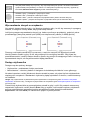
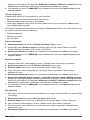
Installation startup checklist
1. Reconnect the battery pack in order to supply power to the instrument as described in Reconnect
battery power on page 7.
2. Switch the machine ON using the ON/OFF switch (No. 2 in Figure 1 on page 8). If the
batteries need charging, connect the instrument to an external power source as described in
External power on page 8.
3. Next, familiarize yourself with using the instrument by reading the next section in this manual
entitled User interface on page 11.
4. Set the date and time of the instrument's internal clock, as described in Basic settings
on page 15.
5. Install the 3100 PC software on your PC as described in PC software installation on page 10.
6. Set up the user configuration table using the PC software as described in Create new user table
on page 10.
7. Set up the measurement configuration table using the PC software as described in Create new
measurement configuration table on page 10.
8. Upload the user and measurement configuration tables to the instrument as described in Transfer
files to the instrument on page 10.
6
English

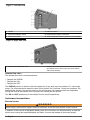
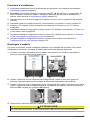
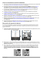
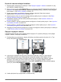
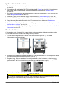
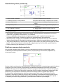
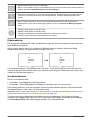
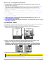
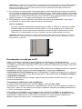
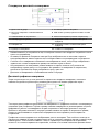
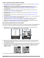
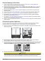
Reconnect battery power
For safety reasons, the battery pack will not be connected during shipment. Once the instrument has
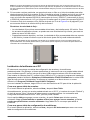
been unpacked, the battery power should be reconnected using the following procedure:
1. Tilt the instrument towards the rear, to reveal two screws underneath (No. 1) that hold the
instrument front panel in place.
2. Using the cross screwdriver supplied in the tool kit, unscrew and remove these screws. Lift off the
front panel to reveal the internal battery power switch (No. 2).
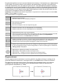
3. Using the long-bladed flat-head screwdriver supplied in the tool kit, turn the switch a quarter of a
turn clockwise to reconnect the battery power. The diagrams below show the switch in the OFF
position as delivered (left) and in the ON position (right).
4. Replace the front panel and secure back in place with the two screws.
C A U T I O N
To avoid any damage to the instrument, it will be necessary to perform the above procedure in reverse (i.e.
turn the connection OFF) prior to any future transportation of this instrument.
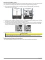
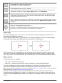
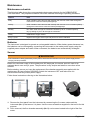
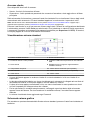
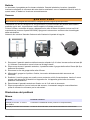
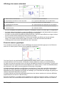
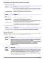
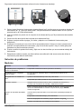
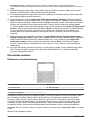
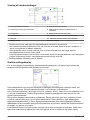
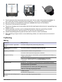
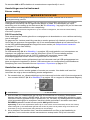
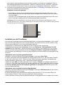
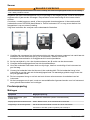
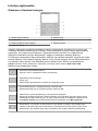
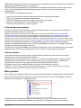
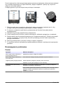
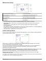
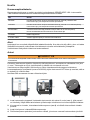
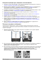
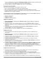
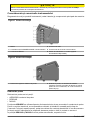
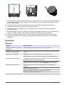
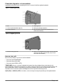
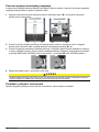
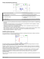
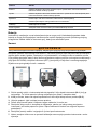
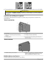
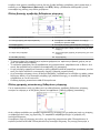
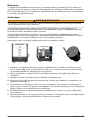
Instrument switches and connectors
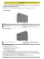
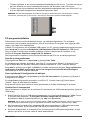
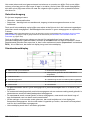
The following diagrams illustrate the side views of the instrument and their key features:
English
7

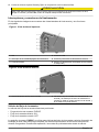
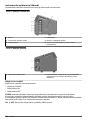
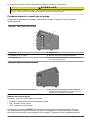
Figure 1 Left side view
1 Handle 4 USB connection
2 Instrument ON/OFF switch 5 External power supply connection
3 RS232 connection 6 Card identification system (option not yet available)
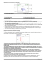
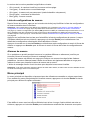
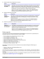
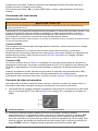
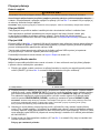
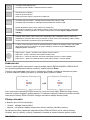
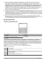
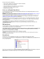
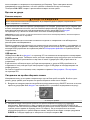
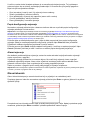
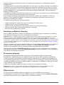
Figure 2 Right side view
1 Sample flow adjustment valve 2 Sample flow valve with inlet and outlet connections
(the sample inlet is at the top of the valve and the
outlet at the bottom).
Sample flow valve
The sample flow valve has three positions:
• Sample line PURGE
• Sample flow ON
• Sample flow OFF
The PURGE position is used to clear the sample line of any build up of air bubbles. For a thorough
purge, it is recommended to keep the valve in this position for 5 seconds. During this operation, the
sample flows directly from the inlet tubing to the outlet tubing. All measurements are suspended
during this time as the sample does not come into contact with the sensor.
The ON and OFF positions turn the sample flow on and off respectively.
Instrument connections
External power
W A R N I N G
When using an external power supply to power the instrument, ensure the external power socket is earthed.
In addition to the internal rechargeable battery pack, the instrument can be powered by an external
power source using the supplied adapter and cable. Connect the adapter to the power supply
8
English

connection socket on the instrument (No. 5 in Figure 1 on page 8), and plug into an external power
supply socket.
Note: When the instrument is connected to an external power source, the internal battery pack is automatically
recharged.
RS232 connection
This connection can be used to download measurement data and for real-time monitoring of the
measurements.
The data sent to the PC via this link is identical in format and content to that stored in the
measurement file on the instrument and which can be transferred using the USB mass storage
device (see Exported files on page 19 for details).
USB connection
The USB connection (No. 4 in Figure 1 on page 8) is used for exporting and importing data from and
to the instrument. Tables can be set up on the PC using the 3100 PC software application and then
uploaded to the instrument using a USB mass storage device.
In addition, tables can be exported from the instrument to the USB storage device and then imported
to other 3100 instruments to standardize configurations.
For more details on this, refer to Import / Export on page 18.
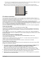
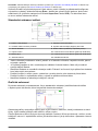
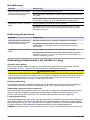
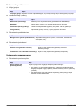
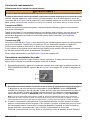
Connecting sample lines
Measurements can be taken on a continuous or sample by sample basis. In either mode, the
instrument must be connected to the sample line as follows:
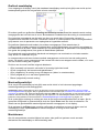
1. The sample inlet and outlet connections on the instrument are located on the ON/OFF sample
flow valve (No. 8 in Figure 2 on page 8 and enlarged in the diagram below):
1 Sample inlet 2 Sample outlet
2. Connect the inlet and outlet tubing to the sample source and to the drain, respectively. The
diagram above, shows the valve in the OFF position. To turn the sample flow fully ON, turn the
valve counter-clockwise until it clicks into position (about 1/8th of a turn). To remove any residual
air bubbles from the sample line, turn the valve to the PURGE position for 5 seconds before
turning to the ON position.
Note: A length of stainless steel tubing is supplied in the tool kit (4mm instrument version only) and can be
used instead of the plastic tubing on the outlet valve if the pressure in the instrument is high enough to cause
excessive movement of the plastic tubing.
3. If the sample contains particles, it is recommended to use a filter on the inlet tube to avoid any
clogging of the sample flow. The filter (including a box of 10 meshes) is contained in the tool kit
supplied with the instrument. It is also available separately as spare part number DG33216 (4mm
instrument), DG33317 (6mm instrument) or DG33318 (1/4 inch instrument) and the set of
10 meshes as spare part number DG33217.
4. Control the sample flow using the adjustment valve (No. 7 in Figure 2 on page 8) located above
the sample flow valve.
Flow rate guidelines:
• For cans and bottles the minimum recommended flow rate is 150mL/min. For small volume
packages a lower flow rate can be used but this should not be below 100mL/min.
English
9

• For tank and in-line applications the recommended flow rate should be above 200mL/min and
up to a maximum of having the flow adjustment valve fully open.
Note: The flow rates indicated with arrows on the flow meter (as illustrated below) are approximately
150mL/min (lower arrow) and 200mL/min (upper arrow). The silver bead gives an indication of the flow rate.
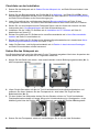
PC software installation
The instrument is delivered with default user and measurement configuration tables. However, to
personalize the instrument by setting up your own tables you will need to use the PC software which
is included on the USB key supplied with the tool kit.
Install the PC software by inserting the USB key into your PC and running the setup program
(entitled setup.exe) from the directory Orbisphere 3100\Installation Files\PC Software on the USB
drive. Follow the on-screen instructions and the software will be installed on your hard disk in a new
directory: C:\Program Files\Hach Lange\3100 PC Software\.
Once the software has been installed, click on the desktop icon on the PC to launch the application.
Create new user table
From the application’s File menu, select New and then User Table.
A default user is created automatically, with an ID of “0”, a User Name of “Default”, and a level of
“User”. None of these fields can be changed. The password is set automatically to “1234”, but this
can be changed.
Use the Add option to add new users, and Delete to remove existing users. Copy and Paste can
also be used to add new users, and Cut can be used to delete existing users. Double click on a field
to edit the contents.
Create new measurement configuration table
From the application’s File menu, select New and then O2 Instrument to create a new
measurement configuration table.
A default entry is created automatically, with an ID of “0”, a Location Name and Product Name of
“Default”. None of these fields can be changed.
Use the same functionality as described for the user table, to add entries to the table.
Transfer files to the instrument
When the two tables have been populated, they can be transferred to the instrument using a USB
storage device (typically a USB key).
1. From the PC copy the files to the USB storage device in a top-level directory of 3100. The files
will typically be located in: C:\Program Files\Hach Lange\3100 PC Software\ with file
extensions of .cdm (for measurement configurations) and .ndu (for user tables).
Note: It is important that the file name extensions (.cdm and .ndu) are not changed as they will not be
recognized by the instrument software. Similarly, the files must be located in a top-level directory of 3100.
2. With the instrument switched ON, insert the USB storage device into the USB connection on the
left side of the instrument, and press the USB icon on the instrument front panel.
3. The first screen is for exporting files from the instrument to a USB storage device, so press the
right arrow to move to the next screen.
10
English

4. The next screen is the Import User Table screen. The user table will be recognized by the
instrument and the file name displayed in the highlighted box. If more than one user table is on
the USB storage device, press the Enter key to view a list of all the user tables, and use the
up/down arrows to scroll through the list. Press the Enter key to select. When a table has been
selected, press the down arrow key until the Import File text is highlighted and press the Enter
key to import the file. On completion, a message will appear saying the instrument will have to be
turned off and on again for the new table to take effect, but as the measurement configuration
table is still to be imported this message can be ignored at this stage.
5. Press the right arrow to move to the Import Measurement Configurations screen. As with the
user table, select the measurement configuration table to import and press the down arrow key
until the Import File text is highlighted. Press the Enter key to import the file. Again, on
completion, a message will appear saying the instrument will have to be turned off and on again
for the new table to take effect.
6. As both tables have now been transferred to the instrument, turn the instrument OFF and then
back ON again for the new tables to take effect. When switched ON the two default table entries
will be loaded (i.e. default user and default measurement configuration).
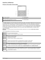
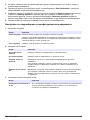
User interface
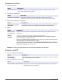
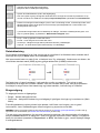
Keypad and function keys
1 Cancel key 5 Enter key
2 USB key 6 RFID key
3 Sample or continuous mode key 7 Measurement key
4 Arrow keys
The user interface of the instrument consists of a display screen, 6 function keys and a set of 4 arrow
keys in the center. A green light at the bottom left of the keypad indicates if the instrument is ON. No
light indicates the instrument is OFF. The keypad is touch sensitive and will respond to each key
being pressed. As the key is touched a blue light will be appear underneath to indicate selection of
that key. If a key is selected that is not available or has no meaning during the current operation, then
the key will be displayed above the measurement value with a line drawn through it.
Note: The keypad can be locked and unlocked pressing the keys RFID, USB and RFID in sequence.
The keys have the following functions:
• Cancel data input.
• Exit from a menu and display the measurement screen.
• Display the main menu.
• Select an option.
• Validate the input and go on to the next step.
English 11

• Import data from a USB mass storage device.
• Export data to a USB mass storage device.
• Card identification system (not yet available).
• When pressed twice in quick succession a screenshot will be taken (maximum of 10) that can be
transferred to a USB key using the Import / Export option from the Main Menu.
• Define if measurements are in sample or continuous mode. Continuous mode displays the bottle
symbol with a cross through it in the top right of the measurement screen. Sample mode displays
the bottle symbol without the cross.
• When in sample mode use this icon to Start/Stop measurements. When started the bottle symbol is
shown in green. When stopped the symbol is greyed out and a “Measurement stopped” message
displayed.
• Up arrow - Scroll up through a list or menu.
• Down arrow - Scroll down through a list or menu.
• Left arrow - Go back to the previous screen (or data element) in sequence.
• Right arrow - Go to the next screen (or data element) in a sequence.
Data entry
To select a data item from a list, use the up and down arrow keys to highlight the required value,
followed by the Enter key to select it.
When required to enter data (e.g. a password in the following example), a screen will be displayed
showing the field default value (0000) and the valid range (0 - 9999) below it.
The first character will be highlighted in red with arrows above and below. Press the up and down
arrow keys to increase or decrease the value. When the correct value is showing, press the right
arrow key to move to the next character and enter that value until all characters have been entered.
User access
Two access levels are available:
• User - basic measurement functions
• Supervisor - password protected with access to additional views and the Main Menu
From the measurement screen, press the right arrow key until the list of users stored in the
instrument is displayed. Standard users will be displayed in green and supervisors in blue.
Note: These user lists are defined by the user on the PC (see Create new user table on page 10) and imported into
the instrument (see Transfer files to the instrument on page 10).
Press the up and down arrow keys to scroll through the list of users. When the required one is
highlighted press the Enter key to select it. If a supervisor level user is selected a password will be
required (by default Supervisor1 is 5678). On completion, the display returns to the measurement
screen.
12
English

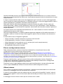
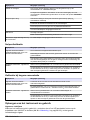
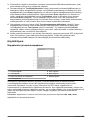
Standard measurement display
1 Instrument date and time 7 Battery life remaining
2 Measurement location and product name 8 USB symbol indicates USB key attached
3 User name 9 Measurement mode (continuous shown)
4 Sample temperature 10 High level alarm value (if set)
5 Measured gas 11 Low level alarm value (if set)
6 Measurement unit 12 Measurement value
• The user name will be displayed in green for a standard user, or blue for a supervisor
• The battery life remaining will not be displayed if using mains power supply, instead the icon will
show the battery recharging symbol
• The measurement value is normally displayed in blue, but will be displayed in red if it is outside the
high or low value alarm limits
• If measurement is in sample mode, the bottle icon is displayed at the top right of the screen. If
measurement mode is set to continuous, the bottle icon will be displayed with a cross through it
• The measurement display is refreshed every 5 seconds
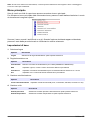
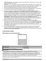
Graphical measurement display
To access this display from the standard measurement display screen, press the right arrow key on
the keypad until the graphic screen is displayed:
This screen gives a graphical representation of the measurement with the numeric value of the
measurement displayed at the end of the curve. The above example shows the measurement in
sample mode.
The numeric measurement value at the end of the curve is refreshed every 5 seconds. The curve is
refreshed every 5 seconds in sample mode. In continuous mode, the refreshment rate is the same as
that defined as the storage interval parameter.
The graphic timescale is displayed at the bottom of the screen. This value can be increased or
decreased (4 zoom levels) by pressing the up and down arrows on the keyboard. These values are
also dependant on the storage interval parameter; the greater the storage interval, the greater the
available timescale.
The measurement scale is calculated automatically with the maximum and minimum values
displayed at the top and bottom of the y axis respectively.
In sample mode, a square symbol is displayed to denote the end of the measurement . This is
displayed in green if the stop criteria are met, or red to denote an erroneous measurement.
English
13

The color of the curve has the following meaning:
• Grey (normal): The channel is out or the measurement is out of range
• Green (bold): The channel is being calibrated
• Grey (bold): The measurement has not started (sample mode only)
• Red (bold): An alarm has been activated
• Blue (bold): Normal measurement
Measurement configuration list
From the measurement screen, press the right arrow key until the list of measurement configurations
stored in the instrument is displayed.
Note: These configurations are defined by the user on the PC (see Create new measurement configuration table
on page 10) and imported into the instrument (see Transfer files to the instrument on page 10). Only the default
configuration (ID0) can be edited by the user from the instrument. To do this the user must be logged on at
supervisor level and the default parameters can then be edited from the Main Menu as described in Default
measurement configuration settings on page 17.
Press the up and down arrow keys to scroll through the list of measurement configurations. When the
required one is highlighted press the Enter key to select it. The selected configuration details will be
displayed on screen.
Press the Enter key again to select this configuration and return to the measurement screen, or
Cancel to reject it and return to the measurement configuration list screen.
Measurement alarms
If a problem occurs during measurement, the system will alternate every second between the
measurement screen and the error message screen.
The measurement value is displayed in red to indicate a measurement outside the pre-defined alarm
limits. The alarm low value on the right side of that screen is also displayed in red to indicate the
reason the measurement value is in error.
The error message screen gives the reason why the measurement is invalid.
Note: If the measured value goes back above this low value, the value is again displayed in blue and the error
message screen is no longer shown.
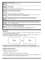
Main menu
The main menu is only available to users logged on at supervisor level.
To access the main menu from the measurement screen, press the Enter key on the main keypad to
display the following options:
Scroll through the menu using the up and down arrow keys. When the required option is highlighted,
press the Enter key to select it and display the sub option screens.
14
English

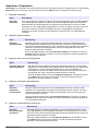
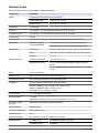
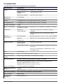
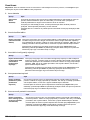
Basic settings
1. Language selection
Option Description
Language Select the working language for the instrument from the list available
2. Date and time adjustment
Option Description
Date format Define the display format for the date (DD/MM/YY or MM/DD/YY)
Date Enter the day, the month and the year in the format defined above
Time format Enter the display format for the time using a 12 or 24 hour clock
Time Enter the hour and minutes in the format defined above
3. Backlight management
Option Description
Backlight level Enter the scale of brightness (max, comfortable, standard, economy or min)
4. Units management
Option Description
Pressure unit Choose the barometric pressure unit from the list available
Temperature unit Choose the temperature unit from the list available
Advanced settings
1. File measurement management
Option Description
Storage
mode
Choose from a rolling buffer or store once:
• Rolling buffer: When the file is full, the latest measurement set replaces the oldest one
continuously (first-in, first-out)
• Store once: When the file is full (5,760 positions), the recording of measurement stops
Storage
interval
Define the interval for storing measurements from the list available.
The interval is in seconds with the number of hours of measurements available shown in
brackets e.g. 10s (16h) indicates measurements are stored every 10 seconds, which will
give 16 hours of continuous storage
Note: This parameter also defines the refreshment rate for the graphic measurement
display.
Clear data Select this option to erase the measurement storage file
2. Communication
Option Description
RS232 Check the box if the RS232 link is required
Baud rate Select the baud rate from the list available
3. Miscellaneous
Option Description
Miscellaneous This option allows the default measurement configuration parameters to be restored
English 15

Calibration
Barometric sensor calibration
1. The upper box shows the current barometric pressure as measured by the instrument. Using a
precision certified barometer, measure the barometric pressure in the location where the
instrument is used. If the values differ, enter the correct value in the box provided and select
Validate calibration
Gas sensor calibration
There are two calibration modes available
• Zero calibration
• High level adjustment
The zero calibration method is the best method to guarantee the sensor specifications.
To get more accurate measurements for samples with higher oxygen concentrations (above 1%
oxygen which corresponds to about 400 ppb dissolved O
2
) a high level adjustment can be performed
using a gas mixture containing 2% oxygen. However, this should not be done without first ensuring
the zero point is accurate (i.e. by performing a zero calibration first).
Zero calibration
1. Rinse flow path with 20 mL of ethanol (EtOH) using the syringe and connectors supplied in the
tool kit
2. Connect a cylinder of oxygen free gas (minimum 99.9% purity) to the instrument and adjust the
flow to approximately 100 mL/min
3. Let the oxygen free gas run through the instrument for 5 minutes
4. Press the Enter key to start the calibration
5. Wait until the Signal in range and Stability reached fields display Yes which indicates the
calibration is within acceptable limits. The Calibration possible field should also display Yes at
this point. Press the Enter key to complete the calibration
6. Accept (OK) or reject (Cancel) the new calibration data
High level adjustment
There are three possible modes for high level adjustments:
• Using a reference gas mixture (gas cylinder)
• Using a known oxygen sample (reference sample)
• Enter a factory parameter provided by Hach Lange (this option is only required when the sensor
spot has been replaced)
If the calibration mode displayed is not the required mode, then press the Enter key and select the
required mode from the three options available in the drop-down list:
• Factory parameter
• Reference sample
• Ref. gas bottle
Factory parameter
1. In the Calibration mode window select Factory parameter
2. Scroll down to the Reference value window and enter the factory parameter as found on the
package of the LDO spot (model number DG33218)
3. Scroll down to the Start Calibration window and press the Enter key to start the calibration
4. Accept (OK) or reject (Cancel) the new calibration data
16
English

Reference sample
1. Run the reference sample through the instrument and adjust the flow to approximately
150 mL/min.
2. In the Calibration mode window select Reference sample
3. Scroll down to the Reference value window and enter the oxygen value of the sample
4. Let the sample run through the instrument for 5 minutes to stabilize the measurement
5. Scroll down to the Start Calibration window and press the Enter key to start the calibration
6. Wait until the Signal in range and Stability reached fields display Yes which indicates the
calibration is within acceptable limits. The Calibration possible field should also display Yes at
this point. Press the Enter key to complete the calibration
7. Accept (OK) or reject (Cancel) the new calibration data
Ref. gas bottle
1. Rinse flow path with 20 mL of ethanol (EtOH) using the syringe and connectors supplied in the
tool kit
2. In the Calibration mode window select Ref. gas bottle
3. Scroll down to the Reference value window and enter the oxygen value of the reference gas in
%Vbar
4. Connect the gas sample to the instrument and adjust the flow to approximately 100 mL/min.
5. Let the gas mixture run through the instrument for 5 minutes to stabilize the measurement
6. Scroll down to the Start Calibration window and press the Enter key to start the calibration
7. Wait until the Signal in range and Stability reached fields display Yes which indicates the
calibration is within acceptable limits. The Calibration possible field should also display Yes at
this point. Press the Enter key to complete the calibration
8. Accept (OK) or reject (Cancel) the new calibration data
Default measurement configuration settings
1. Instrument settings
Option Description
Instrument mode Select between continuous or sample mode.
Continuous mode is typically used for process measurement, whereas sample mode is
aimed at lab measurements of small volume individual samples such as cans, bottles,
etc.
Sample type Select the sample type from the list available
2. O2 channel settings
Option Description
O2 gas unit type Select the gas unit type from the list available
O2 gas unit Select the display unit from the list available
English 17

Option Description
O2 high alarm Check the box to set the measurement high alarm.
If set, enter the high level value to trigger the alarm. When measurements exceed this
value an alarm will be triggered
O2 low alarm Check the box to set the measurement low alarm.
If set, enter the low level value to trigger the alarm. When measurements fall below this
value an alarm will be triggered
3. O2 advanced settings
Option Description
O2 measurement offset If required, enter a value (positive or negative) for the measurement offset. This
value will be used to adjust the measurement accordingly
Import / Export
Note: To import files into the instrument from a USB mass storage device, they must be under a top-level directory
of 3100 for them to be recognized.
1. Export files
Option Description
Export
files
This option allows you to export a number of different files to a USB mass storage device. Once
written to the USB device, it can then be used to load these files to other 3100 instruments or to
a PC.
Make sure a USB device is connected and then press the Enter key to start the process. A
progress bar is displayed at the bottom of the screen.
Wait until the export complete message is displayed on screen before removing the USB
device.
2. Import user table
Option Description
Import
user table
This option allows you to import user tables from a USB mass storage device. These tables
could be exported from other 3100 instruments or from the 3100 software application installed
on your PC. The tables are recognized by having an extension of .ndu. If more than one table is
found on the device, you will need to select the table you want from the list.
Press the down arrow key to highlight the Import File option and press the Enter key to start
the process. You will need to restart the instrument before the new table takes effect.
3. Import measurement configuration table
Option Description
Import
measurement
configuration
table
This option allows you to import measurement configuration tables from a USB mass
storage device. These tables could be exported from other 3100 instruments or from the
3100 software application installed on your PC. The tables are recognized by having an
extension of .cdm. If more than one table is found on the device, you will need to select
the table you want from the list.
Press the down arrow key to highlight the Import File option and press the Enter key to
start the process. You will need to restart the instrument before the new table takes
effect.
18 English

4. Import solubility parameters
Option Description
Import
solubility
parameters
This option allows you to import solubility parameters from a USB mass storage device.
The tables are recognized by having an extension of .sol. If more than one file is found on
the device, you will need to select the file you want from the list.
Press the down arrow key to highlight the Import File option and press the Enter key to
start the process. You will need to restart the instrument before the new table takes effect.
5. Import instrument basic settings
Option Description
Import
instrument
basic settings
This option allows you to import instrument user settings from a USB mass storage
device. The tables are recognized by having an extension of .ius. If more than one file is
found on the device, you will need to select the file you want from the list.
Press the down arrow key to highlight the Import File option and press the Enter key to
start the process. You will need to restart the instrument before the new table takes effect.
Exported files
The following files will be automatically exported from the instrument to the USB mass storage device
under a top-level directory of 3100:
• All measurement configuration tables (*.cdm)
• All user tables (*.ndu)
• All solubility tables (*.sol)
• All user settings tables (*.ius)
• Instrument configuration details (InstrumentConf.txt)
• Measurement details (Measurements.txt)
• Instrument model details (Model.txt)
• A number of internal files (*.dat)
The following files can be found under sub-directories CalibrationReports and Screenshots:
• Calibration reports (O2CalibrationReport*.txt)
• Screenshots (View*.bmp)
The text files (*.txt extension) are in a readable format for your PC. Most document editors can be
used to open these files, as well as spreadsheet and other reporting tools.
The measurement configuration tables and user tables can be modified using the PC software (see
PC software installation on page 10).
Service instrument
1. Board information
Option Description
Board information This option is useful for troubleshooting purposes and displays information about the
mother board, measurement board and battery
2. Temperature checking
Option Description
Temperature checking This option is useful for troubleshooting purposes and displays the temperature
readings of the measurement board, pigtail, battery pack and sample
English 19

3. Sample temperature calibration
Option Description
Sample temperature
calibration
You will need a sensor simulator for this option. Follow the on-screen
instructions to calibrate the sample temperature
4. Miscellaneous
Option Description
Enable raw
data logger
Check the box to enable the capture of raw data which is useful for troubleshooting
purposes
Activate
service timer
Check the box to activate the service timer option.
When activated, the instrument will automatically remind the user when the next sensor
service is due.
Enter the Nb of days between services in the box provided. This defines the due date of
the next sensor service.
If activated, select the Reset service timer option each time the instrument has been
serviced. This automatically sets the Last service date parameter to the current date.
Note: The total uptime of the instrument is displayed at the bottom of the screen.
Service O2 channel
1. O2: Calibration parameters
Option Description
O2: Calibration
parameters
This option is useful for troubleshooting purposes and will display a number of
values associated with the measurement channel
2. O2: DC measurement parameters
Option Description
O2: DC measurement
parameters
This option is useful for troubleshooting purposes and will display the
values of the fluorescent and reference LED current
3. O2: AC diagnostic parameters
Option Description
O2: AC diagnostic
parameters
This option is useful for troubleshooting purposes and will display the values of
the fluorescent and reference amplitude and phase, plus the phase shift value
4. O2: Calibration timer
Option Description
Activate
calibration
timer
Check the box to activate the calibration timer option.
When activated, the instrument will automatically remind the user when the next sensor
calibration is due.
The Last calibration date parameter is shown for information. This is automatically
updated each time a calibration is performed on the sensor.
Enter the Nb of days between calibrations in the box provided. This defines the due
date of the next sensor calibration.
20 English
Pagina se încarcă...
Pagina se încarcă...
Pagina se încarcă...
Pagina se încarcă...
Pagina se încarcă...
Pagina se încarcă...
Pagina se încarcă...
Pagina se încarcă...
Pagina se încarcă...
Pagina se încarcă...
Pagina se încarcă...
Pagina se încarcă...
Pagina se încarcă...
Pagina se încarcă...
Pagina se încarcă...
Pagina se încarcă...
Pagina se încarcă...
Pagina se încarcă...
Pagina se încarcă...
Pagina se încarcă...
Pagina se încarcă...
Pagina se încarcă...
Pagina se încarcă...
Pagina se încarcă...
Pagina se încarcă...
Pagina se încarcă...
Pagina se încarcă...
Pagina se încarcă...
Pagina se încarcă...
Pagina se încarcă...
Pagina se încarcă...
Pagina se încarcă...
Pagina se încarcă...
Pagina se încarcă...
Pagina se încarcă...
Pagina se încarcă...
Pagina se încarcă...
Pagina se încarcă...
Pagina se încarcă...
Pagina se încarcă...
Pagina se încarcă...
Pagina se încarcă...
Pagina se încarcă...
Pagina se încarcă...
Pagina se încarcă...
Pagina se încarcă...
Pagina se încarcă...
Pagina se încarcă...
Pagina se încarcă...
Pagina se încarcă...
Pagina se încarcă...
Pagina se încarcă...
Pagina se încarcă...
Pagina se încarcă...
Pagina se încarcă...
Pagina se încarcă...
Pagina se încarcă...
Pagina se încarcă...
Pagina se încarcă...
Pagina se încarcă...
Pagina se încarcă...
Pagina se încarcă...
Pagina se încarcă...
Pagina se încarcă...
Pagina se încarcă...
Pagina se încarcă...
Pagina se încarcă...
Pagina se încarcă...
Pagina se încarcă...
Pagina se încarcă...
Pagina se încarcă...
Pagina se încarcă...
Pagina se încarcă...
Pagina se încarcă...
Pagina se încarcă...
Pagina se încarcă...
Pagina se încarcă...
Pagina se încarcă...
Pagina se încarcă...
Pagina se încarcă...
Pagina se încarcă...
Pagina se încarcă...
Pagina se încarcă...
Pagina se încarcă...
Pagina se încarcă...
Pagina se încarcă...
Pagina se încarcă...
Pagina se încarcă...
Pagina se încarcă...
Pagina se încarcă...
Pagina se încarcă...
Pagina se încarcă...
Pagina se încarcă...
Pagina se încarcă...
Pagina se încarcă...
Pagina se încarcă...
Pagina se încarcă...
Pagina se încarcă...
Pagina se încarcă...
Pagina se încarcă...
Pagina se încarcă...
Pagina se încarcă...
Pagina se încarcă...
Pagina se încarcă...
Pagina se încarcă...
Pagina se încarcă...
Pagina se încarcă...
Pagina se încarcă...
Pagina se încarcă...
Pagina se încarcă...
Pagina se încarcă...
Pagina se încarcă...
Pagina se încarcă...
Pagina se încarcă...
Pagina se încarcă...
Pagina se încarcă...
Pagina se încarcă...
Pagina se încarcă...
Pagina se încarcă...
Pagina se încarcă...
Pagina se încarcă...
Pagina se încarcă...
Pagina se încarcă...
Pagina se încarcă...
Pagina se încarcă...
Pagina se încarcă...
Pagina se încarcă...
Pagina se încarcă...
Pagina se încarcă...
Pagina se încarcă...
Pagina se încarcă...
Pagina se încarcă...
Pagina se încarcă...
Pagina se încarcă...
Pagina se încarcă...
Pagina se încarcă...
Pagina se încarcă...
Pagina se încarcă...
Pagina se încarcă...
Pagina se încarcă...
Pagina se încarcă...
Pagina se încarcă...
Pagina se încarcă...
Pagina se încarcă...
Pagina se încarcă...
Pagina se încarcă...
Pagina se încarcă...
Pagina se încarcă...
Pagina se încarcă...
Pagina se încarcă...
Pagina se încarcă...
Pagina se încarcă...
Pagina se încarcă...
Pagina se încarcă...
Pagina se încarcă...
Pagina se încarcă...
Pagina se încarcă...
Pagina se încarcă...
Pagina se încarcă...
Pagina se încarcă...
Pagina se încarcă...
Pagina se încarcă...
Pagina se încarcă...
Pagina se încarcă...
Pagina se încarcă...
Pagina se încarcă...
Pagina se încarcă...
Pagina se încarcă...
Pagina se încarcă...
Pagina se încarcă...
Pagina se încarcă...
Pagina se încarcă...
Pagina se încarcă...
Pagina se încarcă...
Pagina se încarcă...
Pagina se încarcă...
Pagina se încarcă...
Pagina se încarcă...
Pagina se încarcă...
Pagina se încarcă...
Pagina se încarcă...
Pagina se încarcă...
Pagina se încarcă...
Pagina se încarcă...
Pagina se încarcă...
Pagina se încarcă...
Pagina se încarcă...
Pagina se încarcă...
Pagina se încarcă...
Pagina se încarcă...
Pagina se încarcă...
Pagina se încarcă...
Pagina se încarcă...
Pagina se încarcă...
Pagina se încarcă...
Pagina se încarcă...
Pagina se încarcă...
Pagina se încarcă...
Pagina se încarcă...
Pagina se încarcă...
Pagina se încarcă...
Pagina se încarcă...
Pagina se încarcă...
Pagina se încarcă...
Pagina se încarcă...
Pagina se încarcă...
Pagina se încarcă...
Pagina se încarcă...
Pagina se încarcă...
Pagina se încarcă...
Pagina se încarcă...
Pagina se încarcă...
Pagina se încarcă...
Pagina se încarcă...
Pagina se încarcă...
Pagina se încarcă...
Pagina se încarcă...
Pagina se încarcă...
Pagina se încarcă...
Pagina se încarcă...
Pagina se încarcă...
Pagina se încarcă...
Pagina se încarcă...
Pagina se încarcă...
Pagina se încarcă...
Pagina se încarcă...
Pagina se încarcă...
Pagina se încarcă...
Pagina se încarcă...
Pagina se încarcă...
Pagina se încarcă...
Pagina se încarcă...
Pagina se încarcă...
Pagina se încarcă...
Pagina se încarcă...
Pagina se încarcă...
Pagina se încarcă...
Pagina se încarcă...
Pagina se încarcă...
Pagina se încarcă...
Pagina se încarcă...
Pagina se încarcă...
Pagina se încarcă...
Pagina se încarcă...
Pagina se încarcă...
Pagina se încarcă...
Pagina se încarcă...
Pagina se încarcă...
Pagina se încarcă...
Pagina se încarcă...
Pagina se încarcă...
Pagina se încarcă...
Pagina se încarcă...
Pagina se încarcă...
Pagina se încarcă...
Pagina se încarcă...
Pagina se încarcă...
Pagina se încarcă...
Pagina se încarcă...
Pagina se încarcă...
Pagina se încarcă...
Pagina se încarcă...
Pagina se încarcă...
Pagina se încarcă...
Pagina se încarcă...
Pagina se încarcă...
Pagina se încarcă...
Pagina se încarcă...
Pagina se încarcă...
Pagina se încarcă...
Pagina se încarcă...
Pagina se încarcă...
Pagina se încarcă...
Pagina se încarcă...
Pagina se încarcă...
Pagina se încarcă...
Pagina se încarcă...
Pagina se încarcă...
Pagina se încarcă...
Pagina se încarcă...
Pagina se încarcă...
Pagina se încarcă...
Pagina se încarcă...
Pagina se încarcă...
Pagina se încarcă...
Pagina se încarcă...
Pagina se încarcă...
Pagina se încarcă...
Pagina se încarcă...
Pagina se încarcă...
Pagina se încarcă...
Pagina se încarcă...
Pagina se încarcă...
Pagina se încarcă...
Pagina se încarcă...
Pagina se încarcă...
Pagina se încarcă...
Pagina se încarcă...
Pagina se încarcă...
Pagina se încarcă...
Pagina se încarcă...
Pagina se încarcă...
Pagina se încarcă...
Pagina se încarcă...
Pagina se încarcă...
Pagina se încarcă...
Pagina se încarcă...
Pagina se încarcă...
Pagina se încarcă...
Pagina se încarcă...
Pagina se încarcă...
Pagina se încarcă...
Pagina se încarcă...
Pagina se încarcă...
Pagina se încarcă...
Pagina se încarcă...
Pagina se încarcă...
Pagina se încarcă...
Pagina se încarcă...
Pagina se încarcă...
Pagina se încarcă...
Pagina se încarcă...
Pagina se încarcă...
Pagina se încarcă...
Pagina se încarcă...
Pagina se încarcă...
Pagina se încarcă...
Pagina se încarcă...
Pagina se încarcă...
Pagina se încarcă...
Pagina se încarcă...
Pagina se încarcă...
Pagina se încarcă...
Pagina se încarcă...
Pagina se încarcă...
Pagina se încarcă...
Pagina se încarcă...
Pagina se încarcă...
Pagina se încarcă...
Pagina se încarcă...
Pagina se încarcă...
Pagina se încarcă...
Pagina se încarcă...
Pagina se încarcă...
Pagina se încarcă...
Pagina se încarcă...
Pagina se încarcă...
Pagina se încarcă...
Pagina se încarcă...
Pagina se încarcă...
Pagina se încarcă...
Pagina se încarcă...
Pagina se încarcă...
Pagina se încarcă...
Pagina se încarcă...
Pagina se încarcă...
Pagina se încarcă...
Pagina se încarcă...
Pagina se încarcă...
Pagina se încarcă...
Pagina se încarcă...
Pagina se încarcă...
Pagina se încarcă...
Pagina se încarcă...
-
 1
1
-
 2
2
-
 3
3
-
 4
4
-
 5
5
-
 6
6
-
 7
7
-
 8
8
-
 9
9
-
 10
10
-
 11
11
-
 12
12
-
 13
13
-
 14
14
-
 15
15
-
 16
16
-
 17
17
-
 18
18
-
 19
19
-
 20
20
-
 21
21
-
 22
22
-
 23
23
-
 24
24
-
 25
25
-
 26
26
-
 27
27
-
 28
28
-
 29
29
-
 30
30
-
 31
31
-
 32
32
-
 33
33
-
 34
34
-
 35
35
-
 36
36
-
 37
37
-
 38
38
-
 39
39
-
 40
40
-
 41
41
-
 42
42
-
 43
43
-
 44
44
-
 45
45
-
 46
46
-
 47
47
-
 48
48
-
 49
49
-
 50
50
-
 51
51
-
 52
52
-
 53
53
-
 54
54
-
 55
55
-
 56
56
-
 57
57
-
 58
58
-
 59
59
-
 60
60
-
 61
61
-
 62
62
-
 63
63
-
 64
64
-
 65
65
-
 66
66
-
 67
67
-
 68
68
-
 69
69
-
 70
70
-
 71
71
-
 72
72
-
 73
73
-
 74
74
-
 75
75
-
 76
76
-
 77
77
-
 78
78
-
 79
79
-
 80
80
-
 81
81
-
 82
82
-
 83
83
-
 84
84
-
 85
85
-
 86
86
-
 87
87
-
 88
88
-
 89
89
-
 90
90
-
 91
91
-
 92
92
-
 93
93
-
 94
94
-
 95
95
-
 96
96
-
 97
97
-
 98
98
-
 99
99
-
 100
100
-
 101
101
-
 102
102
-
 103
103
-
 104
104
-
 105
105
-
 106
106
-
 107
107
-
 108
108
-
 109
109
-
 110
110
-
 111
111
-
 112
112
-
 113
113
-
 114
114
-
 115
115
-
 116
116
-
 117
117
-
 118
118
-
 119
119
-
 120
120
-
 121
121
-
 122
122
-
 123
123
-
 124
124
-
 125
125
-
 126
126
-
 127
127
-
 128
128
-
 129
129
-
 130
130
-
 131
131
-
 132
132
-
 133
133
-
 134
134
-
 135
135
-
 136
136
-
 137
137
-
 138
138
-
 139
139
-
 140
140
-
 141
141
-
 142
142
-
 143
143
-
 144
144
-
 145
145
-
 146
146
-
 147
147
-
 148
148
-
 149
149
-
 150
150
-
 151
151
-
 152
152
-
 153
153
-
 154
154
-
 155
155
-
 156
156
-
 157
157
-
 158
158
-
 159
159
-
 160
160
-
 161
161
-
 162
162
-
 163
163
-
 164
164
-
 165
165
-
 166
166
-
 167
167
-
 168
168
-
 169
169
-
 170
170
-
 171
171
-
 172
172
-
 173
173
-
 174
174
-
 175
175
-
 176
176
-
 177
177
-
 178
178
-
 179
179
-
 180
180
-
 181
181
-
 182
182
-
 183
183
-
 184
184
-
 185
185
-
 186
186
-
 187
187
-
 188
188
-
 189
189
-
 190
190
-
 191
191
-
 192
192
-
 193
193
-
 194
194
-
 195
195
-
 196
196
-
 197
197
-
 198
198
-
 199
199
-
 200
200
-
 201
201
-
 202
202
-
 203
203
-
 204
204
-
 205
205
-
 206
206
-
 207
207
-
 208
208
-
 209
209
-
 210
210
-
 211
211
-
 212
212
-
 213
213
-
 214
214
-
 215
215
-
 216
216
-
 217
217
-
 218
218
-
 219
219
-
 220
220
-
 221
221
-
 222
222
-
 223
223
-
 224
224
-
 225
225
-
 226
226
-
 227
227
-
 228
228
-
 229
229
-
 230
230
-
 231
231
-
 232
232
-
 233
233
-
 234
234
-
 235
235
-
 236
236
-
 237
237
-
 238
238
-
 239
239
-
 240
240
-
 241
241
-
 242
242
-
 243
243
-
 244
244
-
 245
245
-
 246
246
-
 247
247
-
 248
248
-
 249
249
-
 250
250
-
 251
251
-
 252
252
-
 253
253
-
 254
254
-
 255
255
-
 256
256
-
 257
257
-
 258
258
-
 259
259
-
 260
260
-
 261
261
-
 262
262
-
 263
263
-
 264
264
-
 265
265
-
 266
266
-
 267
267
-
 268
268
-
 269
269
-
 270
270
-
 271
271
-
 272
272
-
 273
273
-
 274
274
-
 275
275
-
 276
276
-
 277
277
-
 278
278
-
 279
279
-
 280
280
-
 281
281
-
 282
282
-
 283
283
-
 284
284
-
 285
285
-
 286
286
-
 287
287
-
 288
288
-
 289
289
-
 290
290
-
 291
291
-
 292
292
-
 293
293
-
 294
294
-
 295
295
-
 296
296
-
 297
297
-
 298
298
-
 299
299
-
 300
300
-
 301
301
-
 302
302
-
 303
303
-
 304
304
-
 305
305
-
 306
306
-
 307
307
-
 308
308
-
 309
309
-
 310
310
-
 311
311
-
 312
312
-
 313
313
-
 314
314
-
 315
315
-
 316
316
-
 317
317
-
 318
318
-
 319
319
-
 320
320
-
 321
321
-
 322
322
-
 323
323
-
 324
324
-
 325
325
-
 326
326
-
 327
327
-
 328
328
-
 329
329
-
 330
330
-
 331
331
-
 332
332
-
 333
333
-
 334
334
-
 335
335
-
 336
336
-
 337
337
-
 338
338
-
 339
339
-
 340
340
-
 341
341
-
 342
342
-
 343
343
-
 344
344
-
 345
345
-
 346
346
-
 347
347
-
 348
348
-
 349
349
-
 350
350
-
 351
351
-
 352
352
-
 353
353
-
 354
354
-
 355
355
-
 356
356
-
 357
357
-
 358
358
-
 359
359
-
 360
360
-
 361
361
-
 362
362
-
 363
363
-
 364
364
-
 365
365
-
 366
366
-
 367
367
-
 368
368
-
 369
369
-
 370
370
-
 371
371
-
 372
372
-
 373
373
-
 374
374
-
 375
375
-
 376
376
-
 377
377
-
 378
378
-
 379
379
-
 380
380
-
 381
381
-
 382
382
-
 383
383
-
 384
384


Hach Lange ORBISPHERE 3100 Basic User Manual
- Tip
- Basic User Manual
în alte limbi
- Türkçe: Hach Lange ORBISPHERE 3100
- français: Hach Lange ORBISPHERE 3100
- čeština: Hach Lange ORBISPHERE 3100
- English: Hach Lange ORBISPHERE 3100
- suomi: Hach Lange ORBISPHERE 3100
- polski: Hach Lange ORBISPHERE 3100
- Deutsch: Hach Lange ORBISPHERE 3100
- italiano: Hach Lange ORBISPHERE 3100
- español: Hach Lange ORBISPHERE 3100
- svenska: Hach Lange ORBISPHERE 3100
- dansk: Hach Lange ORBISPHERE 3100
- Nederlands: Hach Lange ORBISPHERE 3100
Lucrări înrudite
-
 Hach Lange ORBISPHERE 3100 Basic User Manual
-
 Hach ORBISPHERE 3658 Basic User Manual
-
 Hach POLYMETRON 8810 ISE Basic User Manual
-
 Hach POLYMETRON 8810 ISE Basic User Manual
-
 Hach Polymetron 9611sc PO43-LR Instrucțiuni de utilizare
-
 Hach POLYMETRON 8810 ORP Basic User Manual
-
Hach HQ440d Basic User Manual
-
 Hach 9586sc Basic User Manual
-
 Hach ORBISPHERE 31285TC Basic User Manual
-
 Hach ORBISPHERE 6110 Manual de utilizare


Alte documente
-
Hama 00186434 Air Quality Detector Manualul proprietarului
-
Dräger Pac 7000 Instructions For Use Manual
-
 JBM 53802 Manualul utilizatorului
-
SCANGRIP 03.5626 Instrucțiuni de utilizare
-
-
Beta 1760WM Instrucțiuni de utilizare
-
Weller WXR 3 Manual de utilizare
-
Brady BMP21 Ghid de inițiere rapidă
