Bosch LCD Professional Manualul utilizatorului
- Tip
- Manualul utilizatorului

Robert Bosch Power Tools GmbH
70538 Stuttgart
GERMANY
www.bosch-pt.com
1 609 92A 2MR (2014.04) T / 161
GHG 660 LCD Professional
de Originalbetriebsanleitung
en Original instructions
fr Notice originale
es Manual original
pt Manual original
it Istruzioni originali
nl Oorspronkelijke gebruiksaanwijzing
da Original brugsanvisning
sv Bruksanvisning i original
no Original driftsinstruks
fi Alkuperäiset ohjeet
el Πρωτότυπο οδηγιών χρήσης
tr Orijinal işletme talimatı
pl Instrukcja oryginalna
cs Původní návod k používání
sk Pôvodný návod na použitie
hu Eredeti használati utasítás
ru Оригинальное руководство по
эксплуатации
uk Оригінальна інструкція з
експлуатації
kk Пайдалану нұсқаулығының
түпнұсқасы
ro Instrucţiuni originale
bg Оригинална инструкция
mk Оригинално упатство за работа
sr Originalno uputstvo za rad
sl Izvirna navodila
hr Originalne upute za rad
et Algupärane kasutusjuhend
lv Instrukcijas oriģinālvalodā
lt Originali instrukcija
ar
fa
ςТЎϩХʉ ЌТϾϦφЍʉ ʌμВТЎϺυ
ΖЎϩʉ ˒μВЖЙʉʓ ИͳϞφЁʑ
OBJ_BUCH-485-007.book Page 1 Tuesday, April 19, 2016 4:14 PM

2 |
1 609 92A 2MR | (19.4.16) Bosch Power Tools
Deutsch. . . . . . . . . . . . . . . . . . . . . . . . . . . . . . . . . . . . . . . . . Seite 7
English . . . . . . . . . . . . . . . . . . . . . . . . . . . . . . . . . . . . . . . . . . Page 12
Français . . . . . . . . . . . . . . . . . . . . . . . . . . . . . . . . . . . . . . . . . Page 17
Español. . . . . . . . . . . . . . . . . . . . . . . . . . . . . . . . . . . . . . . . Página 22
Português . . . . . . . . . . . . . . . . . . . . . . . . . . . . . . . . . . . . . . Página 27
Italiano . . . . . . . . . . . . . . . . . . . . . . . . . . . . . . . . . . . . . . . . Pagina 32
Nederlands . . . . . . . . . . . . . . . . . . . . . . . . . . . . . . . . . . . . . Pagina 37
Dansk . . . . . . . . . . . . . . . . . . . . . . . . . . . . . . . . . . . . . . . . . . . Side 42
Svenska . . . . . . . . . . . . . . . . . . . . . . . . . . . . . . . . . . . . . . . . . Sida 46
Norsk. . . . . . . . . . . . . . . . . . . . . . . . . . . . . . . . . . . . . . . . . . . . Side 50
Suomi . . . . . . . . . . . . . . . . . . . . . . . . . . . . . . . . . . . . . . . . . . . Sivu 55
Ελληνικά . . . . . . . . . . . . . . . . . . . . . . . . . . . . . . . . . . . . . . . Σελίδα 59
Türkçe. . . . . . . . . . . . . . . . . . . . . . . . . . . . . . . . . . . . . . . . . . Sayfa 64
Polski . . . . . . . . . . . . . . . . . . . . . . . . . . . . . . . . . . . . . . . . . Strona 69
Česky . . . . . . . . . . . . . . . . . . . . . . . . . . . . . . . . . . . . . . . . . Strana 74
Slovensky . . . . . . . . . . . . . . . . . . . . . . . . . . . . . . . . . . . . . . Strana 79
Magyar . . . . . . . . . . . . . . . . . . . . . . . . . . . . . . . . . . . . . . . . . Oldal 84
Русский . . . . . . . . . . . . . . . . . . . . . . . . . . . . . . . . . . . . Страница 89
Українська . . . . . . . . . . . . . . . . . . . . . . . . . . . . . . . . . . . Сторінка 95
Қазақша . . . . . . . . . . . . . . . . . . . . . . . . . . . . . . . . . . . . . . . . . . Бет 100
Română. . . . . . . . . . . . . . . . . . . . . . . . . . . . . . . . . . . . . . . . Pagina 106
Български . . . . . . . . . . . . . . . . . . . . . . . . . . . . . . . . . . Страница 111
Македонски . . . . . . . . . . . . . . . . . . . . . . . . . . . . . . . . . . . Страна 116
Srpski . . . . . . . . . . . . . . . . . . . . . . . . . . . . . . . . . . . . . . . . . Strana 121
Slovensko . . . . . . . . . . . . . . . . . . . . . . . . . . . . . . . . . . . . . . . Stran 126
Hrvatski. . . . . . . . . . . . . . . . . . . . . . . . . . . . . . . . . . . . . . . Stranica 130
Eesti . . . . . . . . . . . . . . . . . . . . . . . . . . . . . . . . . . . . . . . . Lehekülg 135
Latviešu . . . . . . . . . . . . . . . . . . . . . . . . . . . . . . . . . . . . . . Lappuse 139
Lietuviškai. . . . . . . . . . . . . . . . . . . . . . . . . . . . . . . . . . . . . Puslapis 144
. . . . . . . . . . . . . . . . . . . . . . . . . . . . . . . . . . . . . . . . . 150
. . . . . . . . . . . . . . . . . . . . . . . . . . . . . . . . . . . . . . . 155
OBJ_BUCH-485-007.book Page 2 Tuesday, April 19, 2016 4:14 PM

3 |
1 609 92A 2MR | (19/4/16) Bosch Power Tools
5
4
3
1
1
2
1
2
6
7
9
3
10
2
8
1
GHG 660 LCD
OBJ_BUCH-485-007.book Page 3 Tuesday, April 19, 2016 4:14 PM

1 609 92A 2MR | (19/4/16) Bosch Power Tools
4 |
HDPE 300 °C
PVC (hard) 300 °C
PVC (soft) 400 °C
PP 260 °C
LDPE 250 °C
HDPE 300 °C
PVC (hard) 300 °C
PVC (soft) 400 °C
PP 260 °C
LDPE 250 °C
ABS 350 °C
450 °C
450 °C
75 mm 1 609 390 451
50 mm 1 609 201 795
75 mm 1 609 390 452
50 mm 1 609 201 796
32 mm 1 609 390 453
HDPE 1 609 201 807
PVC (hard) 1 609 201 808
PVC (soft) 1 609 201 809
PP 1 609 201 810
LDPE 1 609 201 811
1 609 201 798
1 609 201 797
11
12
13
15
14
16
D
C
B
A
OBJ_BUCH-485-007.book Page 4 Tuesday, April 19, 2016 4:14 PM

5 |
1 609 92A 2MR | (19.4.16) Bosch Power Tools
550 °C
FE 550 °C
PVC (hard) 300 °C
300 °C
Ø 9 mm 1 609 201 797
Ø 14 mm 1 609 201 647
Ø 20 mm 1 609 201 648
Ø 1,6
–
4,8 mm 1 609 201 812
Ø 4,8
–
9,5 mm 1 609 201 813
32 mm 1 609 390 453
80 mm 1 609 201 751
Ø 9 mm 1 609 201 797
Ø 14 mm 1 609 201 647
Ø 20 mm 1 609 201 648
80 mm 1 609 201 751
32 mm 1 609 390 453
16
17
18
16
G
F
E
OBJ_BUCH-485-007.book Page 5 Tuesday, April 19, 2016 4:14 PM

1 609 92A 2MR | (19.4.16) Bosch Power Tools
6 |
OBJ_BUCH-485-007.book Page 6 Tuesday, April 19, 2016 4:14 PM

Deutsch | 7
Bosch Power Tools 1 609 92A 2MR | (19.4.16)
Deutsch
Sicherheitshinweise
Lesen Sie alle Sicherheitshinweise und Anwei-
sungen. Versäumnisse bei der Einhaltung der
Sicherheitshinweise und Anweisungen können
elektrischen Schlag, Brand und/oder schwere
Verletzungen verursachen.
Bewahren Sie alle Sicherheitshinweise und Anweisun-
gen für die Zukunft auf.
Dieses Heißluftgebläse ist nicht
vorgesehen für die Benutzung
durch Kinder und Personen mit ein-
geschränkten physischen, sensori-
schen oder geistigen Fähigkeiten
oder mangelnder Erfahrung und
Wissen.
Dieses Heißluftgebläse kann von
Kindern ab 8 Jahren und Personen
mit eingeschränkten physischen,
sensorischen oder geistigen Fähig-
keiten oder mangelnder Erfahrung
und Wissen benutzt werden, wenn
sie durch eine für ihre Sicherheit
verantwortliche Person beaufsich-
tigt werden oder von dieser im si-
cheren Umgang mit dem Heißluft-
gebläse eingewiesen worden sind
und die damit verbundenen Gefah-
ren verstehen.
Andernfalls besteht
die Gefahr von Fehlbedienung und
Verletzungen.
Beaufsichtigen Sie Kinder.
Damit
wird sichergestellt, dass Kinder nicht
mit dem Heißluftgebläse spielen.
Die Reinigung und Wartung des
Heißluftgebläses durch Kinder darf
nicht ohne Aufsicht erfolgen.
Gehen Sie sorgsam mit dem Elektrowerkzeug um. Das
Elektrowerkzeug erzeugt starke Hitze, die zu erhöhter
Brand- und Explosionsgefahr führt.
Seien Sie besonders vorsichtig, wenn Sie in der Nähe
brennbarer Materialien arbeiten. Der heiße Luftstrom
bzw. die heiße Düse können Staub oder Gase entzünden.
Arbeiten Sie mit dem Elektrowerkzeug nicht in explo-
sionsgefährdeter Umgebung.
Richten Sie den heißen Luftstrom nicht für längere Zeit
auf ein und dieselbe Stelle. Leicht entzündliche Gase
können z.B. bei der Bearbeitung von Kunststoffen, Farben,
Lacken oder ähnlichen Materialien entstehen.
Beachten Sie, dass Wärme zu verdeckten brennbaren
Materialien geleitet werden und diese entzünden kann.
Legen Sie das Elektrowerkzeug nach Gebrauch sicher
ab und lassen Sie es vollständig auskühlen, bevor Sie
es wegpacken. Die heiße Düse kann Schaden anrichten.
Lassen Sie das eingeschaltete Elektrowerkzeug nicht
unbeaufsichtigt.
Bewahren Sie unbenutzte Elektrowerkzeuge außer-
halb der Reichweite von Kindern auf. Lassen Sie Perso-
nen das Elektrowerkzeug nicht benutzen, die mit die-
sem nicht vertraut sind oder diese Anweisungen nicht
gelesen haben. Elektrowerkzeuge sind gefährlich, wenn
sie von unerfahrenen Personen benutzt werden.
Halten Sie das Elektrowerkzeug von Regen oder Nässe
fern. Das Eindringen von Wasser in ein Elektrowerkzeug
erhöht das Risiko eines elektrischen Schlages.
Zweckentfremden Sie das Kabel nicht, um das Elektro-
werkzeug zu tragen, aufzuhängen oder um den Stecker
aus der Steckdose zu ziehen. Halten Sie das Kabel fern
von Hitze, Öl, scharfen Kanten oder sich bewegenden
Geräteteilen. Beschädigte oder verwickelte Kabel erhö-
hen das Risiko eines elektrischen Schlages.
Tragen Sie immer eine Schutzbrille. Eine Schutzbrille
verringert das Risiko von Verletzungen.
Ziehen Sie den Stecker aus der Steckdose, bevor Sie
Geräteeinstellungen vornehmen, Zubehörteile wech-
seln oder das Elektrowerkzeug weglegen. Diese Vor-
sichtsmaßnahme verhindert den unbeabsichtigten Start
des Elektrowerkzeuges.
Überprüfen Sie vor jeder Benutzung Elektrowerkzeug,
Kabel und Stecker. Benutzen Sie das Elektrowerkzeug
nicht, sofern Sie Schäden feststellen. Öffnen Sie das
Elektrowerkzeug nicht selbst und lassen Sie es nur von
qualifiziertem Fachpersonal und nur mit Original-Ersatz-
teilen reparieren. Beschädigte Elektrowerkzeuge, Kabel
und Stecker erhöhen das Risiko eines elektrischen Schlages.
Belüften Sie Ihren Arbeitsplatz gut. Beim
Arbeiten entstehende Gase und Dämpfe
sind häufig gesundheitsschädlich.
Tragen Sie Schutzhandschuhe und berühren Sie die
heiße Düse nicht. Es besteht Verbrennungsgefahr.
Richten Sie den heißen Luftstrom nicht auf Personen
oder Tiere.
Verwenden Sie das Elektrowerkzeug nicht als Haar-
trockner. Der austretende Luftstrom ist wesentlich heißer
als bei einem Haartrockner.
Wenn der Betrieb des Elektrowerkzeugs in feuchter
Umgebung nicht vermeidbar ist, verwenden Sie einen
Fehlerstromschutzschalter. Der Einsatz eines Fehler-
OBJ_BUCH-485-007.book Page 7 Tuesday, April 19, 2016 4:14 PM

8 | Deutsch
1 609 92A 2MR | (19.4.16) Bosch Power Tools
stromschutzschalters vermindert das Risiko eines elektri-
schen Schlages.
Benutzen Sie das Elektrowerkzeug nicht mit beschä-
digtem Kabel. Berühren Sie das beschädigte Kabel
nicht und ziehen Sie den Netzstecker, wenn das Kabel
während des Arbeitens beschädigt wird. Beschädigte
Kabel erhöhen das Risiko eines elektrischen Schlages.
Produkt- und Leistungsbeschreibung
Bitte klappen Sie die Aufklappseite mit der Darstellung des
Elektrowerkzeugs auf, und lassen Sie diese Seite aufgeklappt,
während Sie die Betriebsanleitung lesen.
Bestimmungsgemäßer Gebrauch
Das Elektrowerkzeug ist bestimmt zum Verformen und Ver-
schweißen von Kunststoff, Entfernen von Farbanstrichen und
zum Erwärmen von Schrumpfschläuchen. Es ist auch geeig-
net zum Löten und Verzinnen, Lösen von Klebeverbindungen
und zum Auftauen von Wasserleitungen.
Abgebildete Komponenten
Die Nummerierung der abgebildeten Komponenten bezieht sich
auf die Darstellung des Elektrowerkzeuges auf der Grafikseite.
1 Ablagefläche
2 Abdeckung mit Grobschmutzfilter
3 Ein-/Ausschalter mit Stufenwahl
4 Düse
5 Wärmeschutz
6 Programmwahltaste
7 Display
8 Taste für Luftmengenregulierung
9 Taste für Temperaturregulierung
10 Speichertaste
11 Flächendüse*
12 Glasschutzdüse*
13 Reflektordüse*
14 Schweißdraht*
15 Schweißschuh*
16 Reduzierdüse*
17 Schrumpfschlauch*
18 Winkeldüse*
*Abgebildetes oder beschriebenes Zubehör gehört nicht zum
Standard-Lieferumfang. Das vollständige Zubehör finden Sie in
unserem Zubehörprogramm.
Geräuschinformation
Messwerte für Geräusch ermittelt entsprechend EN 60745.
Der A-bewertete Schalldruckpegel des Elektrowerkzeugs ist
typischerweise kleiner als 70 dB(A).
Technische Daten
Betrieb
Inbetriebnahme
Beachten Sie die Netzspannung! Die Spannung der
Stromquelle muss mit den Angaben auf dem Typen-
schild des Elektrowerkzeuges übereinstimmen. Mit
230 V gekennzeichnete Elektrowerkzeuge können
auch an 220 V betrieben werden.
Ein-/Ausschalten
Zum Einschalten des Elektrowerkzeugs drücken Sie den Ein-/
Ausschalter 3 in Stellung (siehe „Kaltluftstufe“, Seite 9)
oder (siehe „Heißluftstufe“, Seite 9).
Bei beiden Stellungen startet das Elektrowerkzeug mit den
Luftmengen- und Temperaturwerten, die vor dem letzten Aus-
schalten eingestellt waren.
Zum Ausschalten drücken Sie den Ein-/Ausschalter 3 bis
zum Anschlag in Stellung „0“.
Lassen Sie das Elektrowerkzeug nach längerem Arbeiten mit
hoher Temperatur vor dem Ausschalten zur Abkühlung kurze
Zeit in der Kaltluftstufe laufen.
Thermoschutzabschaltung: Bei Überhitzung (z.B. durch
Luftstau) schaltet das Elektrowerkzeug die Heizung automa-
tisch ab, das Gebläse läuft jedoch weiter. Hat sich das Elek-
trowerkzeug auf Betriebstemperatur abgekühlt, wird die Hei-
zung automatisch wieder zugeschaltet.
Heißluftgebläse GHG 660 LCD GHG 660 LCD
Sachnummer
0 601 944 7.. 0 601 944 7..
Nennspannung
V 220–240 110–120
Nennaufnahmeleistung
W23001400
Luftmenge
l/min 250–500 250–500
Temperatur am Düsenausgang ca.
°C 50–660 50–600
Temperatur-Messgenauigkeit
– am Düsenausgang
–in der Anzeige
±5 %
±5 %
±5 %
±5 %
Betriebstemperatur Display*
°C –20...+70 –20...+70
Gewicht entsprechend EPTA-Procedure 01:2014
kg 1,0 1,0
Schutzklasse
/II /II
* Außerhalb der Betriebstemperatur kann das Display schwarz werden.
OBJ_BUCH-485-007.book Page 8 Tuesday, April 19, 2016 4:14 PM

Deutsch | 9
Bosch Power Tools 1 609 92A 2MR | (19.4.16)
Um Energie zu sparen, schalten Sie das Elektrowerkzeug nur
ein, wenn Sie es benutzen.
Luftmenge regeln
Mit der Taste 8 können Sie die Luftmenge regeln:
Um die Luftmenge zu erhöhen, drücken Sie an der Taste für
Luftmengenregulierung 8 auf „+“, um die Luftmenge zu sen-
ken, drücken Sie auf „–“.
Kurzes Drücken der Taste 8 erhöht bzw. senkt die Luftmenge
um eine Stufe. Längeres Drücken der Taste erhöht bzw. senkt
die Luftmenge fortlaufend, bis die Taste losgelassen wird
oder die maximale bzw. minimale Luftmenge erreicht ist.
Verringern Sie die Luftmenge z.B. dann, wenn die Umgebung
eines Werkstücks nicht übermäßig erhitzt werden soll oder
wenn sich ein leichtes Werkstück durch den Luftstrom ver-
schieben könnte.
Temperatur regeln
Die Temperatur ist nur in der Heißluftstufe regelbar.
Um die Temperatur zu erhöhen, drücken Sie an der Taste für
Temperaturregulierung 9 auf „+“, um die Temperatur zu sen-
ken, drücken Sie auf „–“.
Kurzes Drücken der Taste 9 erhöht bzw. senkt die Temperatur
um 10 °C. Längeres Drücken der Taste erhöht bzw. senkt die
Temperatur fortlaufend um 10 °C, bis die Taste losgelassen
wird oder die maximale bzw. minimale Temperatur erreicht ist.
Bei einer Änderung der Temperatureinstellung benötigt das
Elektrowerkzeug kurze Zeit, um den Luftstrom aufzuwärmen
bzw. abzukühlen. Die Zieltemperatur wird während dieser
Zeit im Display 7 zwischen blinkenden Pfeilen angezeigt. Ist
die Zieltemperatur erreicht, erlöschen die Pfeile, und das
Display zeigt die aktuelle Temperatur an.
Tastensperre („LOC“) aktivieren/deaktivieren
Um ein versehentliches Ändern von Luftmenge und Tempera-
tur zu verhindern, können Sie in der Heißluftstufe die Funk-
tion der Tasten 6, 8, 9 und 10 sperren. In der Kaltluftstufe
kann die Luftmenge auch bei aktivierter Tastensperre verän-
dert werden.
Tastensperre aktivieren:
Schalten Sie das Elektrowerkzeug in der Heißluftstufe ein.
Stellen Sie die Werte für Luftmenge und Temperatur ein, mit
denen das Elektrowerkzeug gesperrt werden soll.
Schalten Sie das Elektrowerkzeug aus.
Halten Sie die Speichertaste 10 gedrückt und schalten Sie
das Elektrowerkzeug wieder ein (Kalt- oder Heißluftstufe). Im
Display 7 erscheint „OFF“ für die deaktivierte Tastensperre.
Drücken Sie nacheinander (bei weiterhin gedrückter Speicher-
taste 10):
– „+“ an der Temperaturtaste 9,
– „+“
an der Luftmengentaste 8,
– „–“ an der Temperaturtaste 9,
– „–“ an der Luftmengentaste 8.
Im Display erscheint „ON“. Lassen Sie die Speichertaste 10
los.
Die Tastensperre ist nun aktiviert. In der Heißluftstufe wer-
den die vorgewählten Werte für Temperatur und Luftmenge
angezeigt. Beim Drücken einer beliebigen Taste erscheint
„LOC“ im Display, die Werte können nicht verändert werden.
Tastensperre deaktivieren:
Schalten Sie das Elektrowerkzeug aus. Halten Sie die Spei-
chertaste 10 gedrückt und schalten Sie es wieder ein. Im Dis-
play erscheint „ON“ für die aktivierte Tastensperre. Drücken
Sie die Temperaturtaste 9 und die Luftmengentaste 8 in der
Reihenfolge wie beim Aktivieren der Tastensperre. Im Display
erscheint „OFF“, die Tastensperre ist deaktiviert.
Betriebsarten
Kaltluftstufe
Luftmenge regelbar, Temperatur festgelegt
auf 50 °C (nicht regelbar), kein Programmbe-
trieb möglich
Die Kaltluftstufe ist geeignet zum Abkühlen eines erhitzten
Werkstücks oder zum Trocknen von Farbe. Sie ist ebenso ge-
eignet, um das Elektrowerkzeug vor dem Abstellen oder dem
Wechsel der Aufsatzdüsen abzukühlen.
Beim Wechsel aus der Heißluftstufe mit höheren Tempera-
turen dauert es kurze Zeit, bis sich das Elektrowerkzeug auf
50 °C abgekühlt hat. Während des Abkühlens wird im Display
7 die tatsächliche Temperatur am Düsenausgang angezeigt.
Beim Wechsel aus der Heißluftstufe zur Kaltluftstufe wer-
den die aktuellen Luftmengeneinstellungen übernommen.
Heißluftstufe
Luftmenge und Temperatur regelbar, Normal-
und Programmbetrieb möglich
Beim Wechsel von der Kaltluftstufe zur Heißluftstufe
werden Luftmenge, Temperatur und gegebenenfalls das Pro-
gramm automatisch so eingestellt wie beim letzten Betrieb in
der Heißluftstufe.
Programmbetrieb
Im Programmbetrieb können Sie Luftmengen- und Tempera-
tureinstellungen dauerhaft in vier Programmen speichern. In
jedem Programm sind beliebige Luftmengen- und Tempera-
turkombinationen möglich.
Auch bei Programmbetrieb können Sie Luftmenge und Tem-
peratur jederzeit ändern. Werden die Änderungen nicht ge-
speichert, gehen sie beim Ausschalten oder beim Wechsel in
ein anderes Programm verloren.
Zum Wechsel in den Programmbetrieb drücken Sie die Pro-
grammwahltaste 6 so oft, bis die Nummer des gewünschten
Programms im Display 7 angezeigt wird.
minimale Luftmenge
maximale Luftmenge
OBJ_BUCH-485-007.book Page 9 Tuesday, April 19, 2016 4:14 PM

10 | Deutsch
1 609 92A 2MR | (19.4.16) Bosch Power Tools
Bei Auslieferung des Elektrowerkzeugs sind folgende vier
Programme voreingestellt:
Zum Ändern eines vorhandenen Programms wechseln Sie
durch Drücken der Programmwahltaste 6 in dieses Pro-
gramm. Stellen Sie mit den Tasten für Luftmengenregulierung
8 und für Temperaturregulierung 9 die gewünschte Luftmen-
ge und Temperatur ein.
Sobald Sie die Werte eines Programms verändert haben,
blinkt links oben im Display das Symbol . Sind die ge-
wünschte Luftmenge und Temperatur eingestellt, dann drü-
cken Sie die Speichertaste 10 so lange, bis das Zeichen
im Display erlischt. Die eingestellten Werte sind nun unter
der im Display angezeigten Programmnummer gespeichert.
Normalbetrieb
Zum Wechsel aus dem Programmbetrieb in den Normalbe-
trieb drücken Sie die Programmwahltaste 6 so oft, bis im Dis-
play keine Programmnummer über der Temperatur angezeigt
wird. Luftmenge und Temperatur sind jederzeit mit den Tas-
ten für Luftmengenregulierung 8 und für Temperaturregulie-
rung 9 änderbar.
Die im Normalbetrieb eingestellten Werte für Luftmenge
und Temperatur bleiben unter folgenden Bedingungen ge-
speichert:
– Wechsel in den Programmbetrieb,
– Wechsel in die Kaltluftstufe,
– Ausschalten des Elektrowerkzeugs.
Arbeitshinweise
Ziehen Sie vor allen Arbeiten am Elektrowerkzeug den
Netzstecker aus der Steckdose.
Hinweis: Bringen Sie die Düse 4 nicht zu nah an das zu bear-
beitende Werkstück. Der entstehende Luftstau kann zur
Überhitzung des Elektrowerkzeugs führen.
Wärmeschutz abnehmen
Für Arbeiten an besonders engen Stellen können Sie den Wär-
meschutz 5 abnehmen.
Vorsicht vor der heißen Düse! Bei Arbeiten ohne Wärme-
schutz besteht erhöhte Verbrennungsgefahr.
Zum Abnehmen bzw. Aufsetzen des Wärmeschutzes 5 schal-
ten Sie das Elektrowerkzeug aus und lassen es abkühlen.
Zum schnelleren Abkühlen können Sie das Elektrowerkzeug
auch kurz in der Kaltluftstufe laufen lassen.
Schrauben Sie den Wärmeschutz 5 entgegen dem Uhrzeiger-
sinn ab bzw. im Uhrzeigersinn wieder auf.
Elektrowerkzeug abstellen (siehe Bild C)
Stellen Sie das Elektrowerkzeug auf den Ablageflächen 1 ab,
um es abkühlen zu lassen oder um beide Hände zum Arbeiten
frei zu haben.
Arbeiten Sie mit dem abgestellten Elektrowerkzeug
besonders vorsichtig! Sie können sich an der heißen
Düse oder am heißen Luftstrom verbrennen.
Arbeitsbeispiele
Die Abbildungen der Arbeitsbeispiele finden Sie auf den Aus-
klappseiten.
Die Temperaturangaben in den Arbeitsbeispielen sind Richt-
werte, die je nach Materialbeschaffenheit abweichen können.
Der Abstand der Düse richtet sich nach dem zu bearbeiten-
den Material.
Die optimale Temperatur für die jeweilige Anwendung lässt
sich durch praktischen Versuch ermitteln. Beginnen Sie im-
mer mit einer niedrigen Temperaturstufe.
Sie können bei allen Arbeitsbeispielen außer „Lack von Fens-
tern entfernen“ ohne Zubehör arbeiten. Der Einsatz der vor-
geschlagenen Zubehörteile vereinfacht jedoch die Arbeit und
erhöht die Qualität des Ergebnisses wesentlich.
Vorsicht beim Düsenwechsel! Berühren Sie die heiße
Düse nicht. Lassen Sie das Elektrowerkzeug abkühlen
und tragen Sie beim Wechsel Schutzhandschuhe. Sie
können sich an der heißen Düse verbrennen.
Lack entfernen/Kleber lösen (siehe Bild A)
Setzen Sie die Flächendüse 11 (Zubehör) auf. Weichen Sie
den Lack kurz mit Heißluft auf und heben Sie ihn mit einem
scharfen, sauberen Spachtel ab. Lange Hitzeeinwirkung ver-
brennt den Lack und erschwert das Entfernen.
Viele Klebemittel (z.B. Aufkleber) werden durch Wärme
weich. Bei erwärmtem Kleber können Sie Verbindungen
trennen oder überschüssigen Kleber entfernen.
Lack von Fenstern entfernen (siehe Bild B)
Verwenden Sie unbedingt die Glasschutzdüse 12
(Zubehör). Es besteht Glasbruchgefahr.
Auf profilierten Flächen können Sie den Lack mit einem pas-
senden Spachtel abheben und mit einer weichen Drahtbürste
abbürsten.
Kunststoffrohre verformen (siehe Bild C)
Setzen Sie die Reflektordüse 13 (Zubehör) auf. Füllen Sie
Kunststoffrohre mit Sand und verschließen Sie sie auf beiden
Seiten, um das Abknicken des Rohres zu verhindern. Erwär-
men Sie das Rohr gleichmäßig durch seitliches Hin- und Her-
bewegen.
Programm
Anwendung
Temperatur
in °C
Luftmenge
1 Kunststoffrohre (z.B. LDPE) verformen 250
2 Kunststoff (z.B. PVC) verschweißen 350
3 Lack entfernen/Kleber lösen 450
4 Löten 550
OBJ_BUCH-485-007.book Page 10 Tuesday, April 19, 2016 4:14 PM

Deutsch | 11
Bosch Power Tools 1 609 92A 2MR | (19.4.16)
Kunststoff verschweißen (siehe Bild D)
Setzen Sie die Reduzierdüse 16 und den Schweißschuh 15
(beide Zubehör) auf. Die zu verschweißenden Werkstücke
und der Schweißdraht 14 (Zubehör) müssen aus dem glei-
chen Material sein (z.B. beide PVC). Die Naht muss sauber
und fettfrei sein.
Erwärmen Sie die Nahtstelle vorsichtig, bis sie teigig wird. Be-
achten Sie, dass der Temperaturbereich zwischen teigigem
und flüssigem Zustand eines Kunststoffes gering ist.
Führen Sie den Schweißdraht 14 zu und lassen Sie ihn in den
Spalt einlaufen, sodass eine gleichmäßige Wulst entsteht.
Schrumpfen (siehe Bild E)
Setzen Sie die Reduzierdüse 16 (Zubehör) auf. Wählen Sie
den Durchmesser des Schrumpfschlauches 17 (Zubehör)
entsprechend dem Werkstück (z.B. Kabelschuh). Erwärmen
Sie den Schrumpfschlauch gleichmäßig.
Wasserleitungen auftauen (siehe Bild F)
Prüfen Sie vor dem Erwärmen, ob es sich tatsächlich
um eine Wasserleitung handelt. Wasserleitungen sind
oft äußerlich nicht von Gasleitungen zu unterscheiden.
Gasleitungen dürfen keinesfalls erwärmt werden.
Setzen Sie die Winkeldüse 18 (Zubehör) auf. Erwärmen Sie
eingefrorene Stellen immer vom Rand zur Mitte.
Erwärmen Sie Kunststoffrohre sowie Verbindungen zwischen
Rohrstücken besonders vorsichtig, um Beschädigungen zu
vermeiden.
Weichlöten (siehe Bild G)
Setzen Sie für Punktlötungen die Reduzierdüse 16, für das
Löten von Rohren die Reflektordüse 13 (beide Zubehör) auf.
Falls Sie Lot ohne Flussmittel verwenden, geben Sie Lötfett
oder Lötpaste auf die Lötstelle. Erwärmen Sie die Lötstelle je
nach Material ca. 50 bis 120 Sekunden. Geben Sie das Lot zu.
Das Lot muss durch die Werkstücktemperatur schmelzen.
Entfernen Sie gegebenenfalls nach dem Erkalten der Lotstelle
das Flussmittel.
Wartung und Service
Wartung und Reinigung
Ziehen Sie vor allen Arbeiten am Elektrowerkzeug den
Netzstecker aus der Steckdose.
Halten Sie das Elektrowerkzeug und die Lüftungs-
schlitze sauber, um gut und sicher zu arbeiten.
Wenn ein Ersatz der Anschlussleitung erforderlich ist, dann
ist dies von Bosch oder einer autorisierten Kundendienststel-
le für Bosch-Elektrowerkzeuge auszuführen, um Sicherheits-
gefährdungen zu vermeiden.
Grobschmutzfilter reinigen
Schieben Sie die Abdeckung 2 mit Grobschmutzfilter nach
hinten aus dem Gehäuse. Blasen Sie den Filter aus (z.B. mit
Druckluft) oder reinigen Sie ihn mit einer weichen Bürste.
Setzen Sie die Abdeckung wieder ein.
Kundendienst und Anwendungsberatung
Der Kundendienst beantwortet Ihre Fragen zu Reparatur und
Wartung Ihres Produkts sowie zu Ersatzteilen. Explosions-
zeichnungen und Informationen zu Ersatzteilen finden Sie
auch unter:
www.bosch-pt.com
Das Bosch-Anwendungsberatungs-Team hilft Ihnen gerne
bei Fragen zu unseren Produkten und deren Zubehör.
www.powertool-portal.de, das Internetportal für Hand-
werker und Heimwerker.
Geben Sie bei allen Rückfragen und Ersatzteilbestellungen
bitte unbedingt die 10-stellige Sachnummer laut Typenschild
des Elektrowerkzeuges an.
Deutschland
Robert Bosch Power Tools GmbH
Servicezentrum Elektrowerkzeuge
Zur Luhne 2
37589 Kalefeld – Willershausen
Unter www.bosch-pt.de können Sie online Ersatzteile bestel-
len oder Reparaturen anmelden.
Kundendienst: Tel.: (0711) 40040480
Fax: (0711) 40040481
E-Mail: Servicezentrum.Ele[email protected]
Anwendungsberatung: Tel.: (0711) 40040480
Fax: (0711) 40040482
E-Mail: Anwendungsbera[email protected]
Österreich
Unter www.bosch-pt.at können Sie online Ersatzteile
bestellen.
Tel.: (01) 797222010
Fax: (01) 797222011
E-Mail: [email protected]
Schweiz
Tel.: (044) 8471511
Fax: (044) 8471551
E-Mail: [email protected]
Luxemburg
Tel.: +32 2 588 0589
Fax: +32 2 588 0595
E-Mail: [email protected]
Entsorgung
Elektrowerkzeuge, Zubehör und Verpackungen sollen einer
umweltgerechten Wiederverwertung zugeführt werden.
Werfen Sie Elektrowerkzeuge nicht in den Hausmüll!
Nur für EU-Länder:
Gemäß der Europäischen Richtlinie
2012/19/EU über Elektro- und Elektronik-
Altgeräte und ihrer Umsetzung in nationales
Recht müssen nicht mehr gebrauchsfähige
Elektrowerkzeuge getrennt gesammelt und
einer umweltgerechten Wiederverwertung
zugeführt werden.
Änderungen vorbehalten.
OBJ_BUCH-485-007.book Page 11 Tuesday, April 19, 2016 4:14 PM

12 | English
1 609 92A 2MR | (19.4.16) Bosch Power Tools
English
Safety Notes
Read all safety warnings and all instructions.
Failure to follow the warnings and instructions
may result in electric shock, fire and/or serious
injury.
Save all safety warnings and all instructions for future
reference.
This hot air gun is not intended for
use by children and persons with
physical, sensory or mental limita-
tions or a lack of experience or
knowledge.
This hot air gun can be used by chil-
dren aged 8 or older and by persons
who have physical, sensory or men-
tal limitations or a lack of experi-
ence or knowledge if a person
responsible for their safety super-
vises them or has instructed them in
the safe operation of the hot air gun
and they understand the associated
dangers. Otherwise, there is a danger
of operating errors and injuries.
Supervise children. This will ensure
that children do not play with the hot
air gun.
Children must not be allowed to
clean and perform maintenance on
the hot air gun without supervision.
Be careful when working with the power tool. The pow-
er tool produces intense heat which can lead to increased
danger of fire and explosion.
Exercise special care when working close to inflamma-
ble materials. The hot air jet or the hot nozzle can ignite
dust or gases.
Do not operate or work with the power tool in areas
where there is danger of explosion.
Never direct the hot air jet at the same position for
longer periods. Easily inflammable gases can develop
e.g., when working plastic, paint, varnish or similar mate-
rials.
Be aware that heat can be conducted to hidden covered
materials and can ignite them.
After using, place the power tool down in a secure man-
ner and allow it to cool down completely before pack-
ing it away. The hot nozzle can cause damage.
Do not leave the switched-on power tool unattended.
Store idle power tools out of the reach of children. Do
not allow persons unfamiliar with the power tool or
these instructions to operate the power tool. Power
tools are dangerous in the hands of untrained users.
Do not expose the power tool to rain or wet conditions.
Water entering a power tool will increase the risk of electric
shock.
Do not abuse the cord. Never use the cord for carrying,
pulling or unplugging the power tool. Keep cord away
from heat, oil, sharp edges or moving parts. Damaged or
entangled cords increase the risk of electric shock.
Always wear safety goggles. Safety goggles will reduce
the risk of injuries.
Disconnect the plug from the socket outlet before mak-
ing any adjustments, changing accessories, or placing
the power tool aside. This safety measure prevents unin-
tentional starting of the power tool.
Check the power tool, cord and plug each time before
use. Do not use the power tool if damage is determined.
Do not open the power tool yourself and have it ser-
viced only by a qualified repair person using only origi-
nal spare parts. Damaged power tools, cords and plugs in-
crease the risk of electric shock.
Provide for good ventilation of your
working place. Gas and vapour developing
during working are often harmful to one’s
health.
Wear safety gloves and do not touch the hot nozzle.
Danger of burning.
Never direct the hot air jet against persons or animals.
Do not use the power tool as a hairdryer. The hot air be-
ing blown out is significantly hotter than that from a hair-
dryer.
When operating the power tool in damp environments
is unavoidable, use a residual current device (RCD).
The use of a residual current device (RCD) reduces the risk
of an electric shock.
Never use the machine with a damaged cable. Do not
touch the damaged cable and pull the mains plug when
the cable is damaged while working. Damaged cables in-
crease the risk of an electric shock.
Products sold in GB only: Your product is fitted with a
BS 1363/A approved electric plug with internal fuse
(ASTA approved to BS 1362).
If the plug is not suitable for your socket outlets, it should
be cut off and an appropriate plug fitted in its place by an
authorised customer service agent. The replacement plug
should have the same fuse rating as the original plug.
The severed plug must be disposed of to avoid a possible
shock hazard and should never be inserted into a mains
socket elsewhere.
OBJ_BUCH-485-007.book Page 12 Tuesday, April 19, 2016 4:14 PM

English | 13
Bosch Power Tools 1 609 92A 2MR | (19.4.16)
Product Description and
Specifications
While reading the operating instructions, unfold the graphics
page for the machine and leave it open.
Intended Use
The power tool is intended for the forming and welding of
plastic, removal of paint and the warming of heat-shrinkable
tubing. It is also suitable for soldering and tinning, loosening
of adhesive joints and the defrosting of water lines.
Product Features
The numbering of the product features refers to the illustra-
tion of the machine on the graphics page.
1 Standing surface
2 Cover with coarse-debris filter
3 On/Off switch with stage selector
4 Nozzle
5 Heat protection collar
6 Program-selection button
7 Display
8 Button for air-flow control
9 Button for temperature control
10 Save button
11 Wide jet nozzle*
12 Glass protection nozzle*
13 Reflector nozzle*
14 Welding rod*
15 Welding shoe*
16 Reduction nozzle*
17 Heat-shrinkable sleeve*
18 Angle nozzle*
*Accessories shown or described are not part of the standard de-
livery scope of the product. A complete overview of accessories
can be found in our accessories program.
Noise Information
Measured sound values determined according to EN 60745.
Typically the A-weighted sound pressure level of the product
is lower than 70 dB(A).
Technical Data
Operation
Starting Operation
Observe correct mains voltage! The voltage of the pow-
er source must agree with the voltage specified on the
nameplate of the machine. Power tools marked with
230 V can also be operated with 220 V.
Switching On and Off
To switch on the power tool, push the On/Off switch 3 to the
position (see “Cool-air Stage”, page 14) or (see “Hot-air
Stage”, page 14).
In both positions, the power tool will start with the previous
set air-flow and temperature values.
To switch off, push the On/Off switch 3 to the stop in position
“0”.
After working for a longer period at a high temperature, oper-
ate the power tool for a short period in the cool-air stage
before switching off.
Thermal-protection shut-off: In case of overheating (e.g.
due to air build-up), the power tool automatically shuts off
the heating system, but the blower will continue to run.
When the power tool has cooled down to the operating tem-
perature, the heating system is automatically switched on
again.
To save energy, only switch the power tool on when using it.
Regulating the Air flow
The air flow can be regulated with the air-flow control
button 8:
To increase the air flow, press on the “+” of the air-flow con-
trol button 8, to decrease the air flow, press on the “–”.
Briefly pressing the air-flow control button 8 at the respective
position increases or decreases the air flow by one step. Pro-
Hot Air Gun GHG 660 LCD GHG 660 LCD
Article number
0 601 944 7.. 0 601 944 7..
Rated voltage
V 220–240 110–120
Rated power input
W23001400
Air flow
l/min 250–500 250–500
Temperature at the nozzle outlet (approx.)
°C 50–660 50–600
Temperature-measuring accuracy
– at the nozzle outlet
– on the display
±5 %
±5 %
±5 %
±5 %
Display operating temperature*
°C –20...+70 –20...+70
Weight according to EPTA-Procedure 01:2014
kg 1.0 1.0
Protection class
/II /II
* The display can turn black when not within the operating temperature.
Minimal air flow
Maximum air flow
OBJ_BUCH-485-007.book Page 13 Tuesday, April 19, 2016 4:14 PM

14 | English
1 609 92A 2MR | (19.4.16) Bosch Power Tools
longed pressing of the air-flow control button continuously in-
creases or decreases the air flow until the button is released,
or the maximum or minimal air flow is reached.
As an example, reduce the air flow when the surrounding area
of a workpiece is not to be heated excessively or when a light
workpiece could be moved away by the air flow.
Setting the Temperature
The temperature can only be regulated in the hot-air stage .
To increase the temperature, press on the “+” of the temper-
ature-control button 9, to decrease the temperature, press on
the “–”.
Briefly pressing the temperature-control button 9 at the re-
spective position increases or decreases the temperature by
10 °C. Prolonged pressing of the temperature-control button
continuously increases or decreases the temperature by
10 °C, until the button is released or the maximum or minimal
temperature is reached.
After a change to the temperature setting, the power tool re-
quires a short period to warm up or cool down the air flow.
During this period, the target temperature is indicated be-
tween the flashing arrows in the display 7. When the target
temperature is reached, the arrows go out and the display in-
dicates the actual temperature.
Activating/Deactivating the Button Lock (“LOC”)
To prevent accidental changing of the air flow and tempera-
ture the function of buttons 6, 8, 9 and 10 can be locked
when in the hot-air stage. In the cool-air stage the air flow
can be changed even when the button lock is activated.
Activating the Button Lock:
Switch the power tool on while in the hot-air stage . Adjust
the air-flow and temperature settings to be locked.
Switch the power tool off.
Press and hold the save button 10 and switch the power tool
on again (in cool-air or hot-air stage). The display 7 will indi-
cate “OFF” for the deactivated button lock.
With the save button 10 still held, press one after the other:
– “+” on the temperature-control button 9,
– “+” on the air-flow control button 8,
– “–” on the temperature-control button 9,
– “–” on the air-flow control button 8.
The display indicates “ON”. Release the save button 10.
The button lock is now activated. The preset values for tem-
perature and air flow are indicated in the hot-air stage . After
pushing any button, “LOC” is indicated in the display and the
values cannot be changed.
Deactivating the Button Lock:
Switch the power tool off. Push and hold the save button 10
and switch the power tool on again. The display indicates
“ON” for the activated button lock. Push the temperature but-
ton 9 and the air-flow control button 8 in the same sequence
as when activating the button lock. The display indicates
“OFF” for the deactivated button lock.
Operating Modes
Cool-air Stage
The air flow can be regulated, the temperature
is set to 50 °C (cannot be regulated), and pro-
gramming operation is not possible.
The cool-air stage is suitable for cooling down a heated-up
workpiece or for drying paint. It is also suitable for cooling down
the power tool before placing it down or changing nozzles.
When changing from the hot-air stage with higher tempera-
tures, it will take a few moments until the power tool has
cooled down to 50 °C. During cooling down, the display 7 in-
dicates the actual temperature at the nozzle outlet.
When changing from the hot-air stage to the cool-air stage
, the current air-flow settings are taken over.
Hot-air Stage
The air flow and temperature can be regulated;
normal and programming operation are possi-
ble.
When changing from the cool-air stage to the hot-air stage
, the air flow, temperature and possibly the program are au-
tomatically adjusted according to the settings of the last hot-
air stage operation.
Programming Operation
In programming operation, it is possible to continuously store
the air-flow and temperature adjustments in four programs.
Each program allows for different air-flow and temperature
combinations.
In progamming operation, it is also possible to change the air
flow and temperature any time. When the changes are not
saved, they are lost after switching off or changing to a differ-
ent program.
To change to programming operation, press the program-
selection button 6 until the number of the requested program
is indicated in the display 7.
The following four programs are preset in the condition of
delivery:
To change a set program, switch to this program by pressing
the program-selection button 6. Set the requested air flow
and temperature with the air-flow control button 8 and the
temperature-control button 9.
Program
Application
Temperature
in °C
Air Flow
1 Deforming plastic tubing (e.g. LDPE) 250
2 Welding plastic (e.g. PVC) 350
3 Removing Varnish/
Softening Adhesives 450
4 Soldering 550
OBJ_BUCH-485-007.book Page 14 Tuesday, April 19, 2016 4:14 PM

English | 15
Bosch Power Tools 1 609 92A 2MR | (19.4.16)
As soon as the settings of a program have been changed, the
symbol flashes in the left top of the display. Once the re-
quested air flow and temperature are set, press the save but-
ton 10 until the symbol in the display goes out. The set val-
ues are now stored under the program number indicated in
the display.
Normal Operation
To switch from programming operation to normal operation,
press the program-selection button 6 as often as required un-
til no program number is indicated above the temperature in
the display. The air flow and temperature can be changed an-
ytime with the air-flow control button 8 and the temperature-
control button 9.
Under the following conditions, the values for air flow and
temperature set in normal operation will remain stored:
– When changing to programming operation,
– When changing to the cool-air stage,
– When switching the power tool off.
Working Advice
Before any work on the machine itself, pull the mains
plug.
Note: Do not apply the nozzle 4 too close to the workpiece
being worked. The hot air build-up can lead to overheating of
the power tool.
Removing the Heat Protection
The heat protection collar 5 can be removed when working at
particularly hard-to-reach locations.
Be careful of the hot nozzle! Increased danger of burning
exists when working without the heat protection collar.
To remove or mount the heat protection collar 5, switch the
power tool off and allow it to cool down.
To cool down the power tool more quickly, you can operate it
for a few moments in the cool-air stage.
Turn the heat protection collar 5 in anticlockwise direction to
remove and in clockwise direction to mount again.
Placing Down the Power Tool (see figure C)
To cool down the power tool or have both hands free, place it
down on the standing surface 1.
Be especially careful when working with the placed
down power tool! There is danger of burning oneself on
the hot nozzle or on the hot air jet.
Work Examples
The illustrations of the work examples can be found on the
fold-out pages.
The temperature settings in the work examples are reference
values that can vary, depending on the material characteris-
tics. The distance between the nozzle and the workpiece de-
pends on the material to be worked.
The optimal temperature for the respective application can be
determined by practical testing. Always start with a low tem-
perature setting.
All application examples can be performed without accesso-
ries except for “Removing Varnish/Paint from Windows”.
However, the use of recommended accessories simplifies the
work and significantly improves the quality of the result.
Be careful when changing the nozzle! Do not touch the
hot nozzle. Allow the power tool to cool down and wear
protective gloves while changing the nozzle. Danger of
burning oneself on the hot nozzle.
Removing Varnish/Softening Adhesives (see figure A)
Mount the wide jet nozzle 11 (accessory). Briefly soften the
varnish applying hot air and remove it using a sharp, clean
scraper or putty knife. Applying heat too long will burn the var-
nish, making it more difficult to remove.
Many adhesives (e.g. of stickers) become soft when heated.
Heated adhesives allow for bonds to be separated or exces-
sive adhesive to be removed.
Removing Varnish/Paint from Windows (see figure B)
Use of the glass protection nozzle 12 (accessory) is es-
sential. Danger of glass breaking.
On profiled surfaces, varnish can be removed using an appro-
priately fitting spatula and brushed off with a soft wire brush.
Shaping Plastic Tubing (see figure C)
Mount the reflector nozzle 13 (accessory). To avoid kinking of
the tubing, fill the tubing with sand and plug both ends. Heat
the tubing evenly by by applying the heat from side to side.
Welding Plastics (see figure D)
Mount the reduction nozzle 16 and the welding shoe 15 (both
accessories). The workpieces to be welded and the welding
rod 14 (accessory) must be of the same material (e.g. both of
PVC). The seam must be clean and grease-free.
Carefully heat up the seam location until it becomes doughy.
Please note that the temperature difference between the
doughy and liquid state of plastic is low.
Feed in the welding rod 14 and allow it to run into the gap so
that a uniform bead is produced.
Shrinking (see figure E)
Mount the reduction nozzle 16 (accessory). Select the diam-
eter of the heat-shrinkable sleeve 17 (accessory) according
to the workpiece (e.g. a cable lug). Heat the heat-shrinkable
sleeve evenly.
Defrosting Water Pipes (see figure F)
Before heating pipes, check to make sure that it is actu-
ally a water pipe. Water lines often do not differ in appear-
ance from gas lines. Gas lines are not to be heated under
any circumstances.
Place on the angle nozzle 18 (accessory). Heat the frozen
zone always from the outside to the middle.
Heat up plastic pipes as well as connections between pipe
pieces especially careful to prevent damage.
Soft Soldering (see figure G)
For point soldering, place on the reduction nozzle 16, for the
soldering of pipes/tubing, place on the reflector nozzle 13
(both accessories).
If solder without flux is used, apply soldering grease or paste
to the location to be soldered. Warm the location to be sol-
OBJ_BUCH-485-007.book Page 15 Tuesday, April 19, 2016 4:14 PM

16 | English
1 609 92A 2MR | (19.4.16) Bosch Power Tools
dered for 50–120 seconds depending on the material. Apply
the solder. The solder must melt from the workpiece temper-
ature. After the soldered location has cooled, remove the flux.
Maintenance and Service
Maintenance and Cleaning
Before any work on the machine itself, pull the mains
plug.
For safe and proper working, always keep the machine
and ventilation slots clean.
If the replacement of the supply cord is necessary, this has to
be done by Bosch or an authorized Bosch service agent in or-
der to avoid a safety hazard.
Cleaning the Coarse-debris Filter
Pull the cover with coarse-debris filter 2 toward the rear out of
the housing. Blow out the filter (e.g. with compressed-air) or
clean it with a soft brush. Reattach the cover with coarse-de-
bris filter.
After-sales Service and Application Service
Our after-sales service responds to your questions concern-
ing maintenance and repair of your product as well as spare
parts. Exploded views and information on spare parts can
also be found under:
www.bosch-pt.com
Bosch’s application service team will gladly answer questions
concerning our products and their accessories.
In all correspondence and spare parts order, please always
include the 10-digit article number given on the type plate of
the machine.
Great Britain
Robert Bosch Ltd. (B.S.C.)
P.O. Box 98
Broadwater Park
North Orbital Road
Denham
Uxbridge
UB 9 5HJ
At www.bosch-pt.co.uk you can order spare parts or arrange
the collection of a product in need of servicing or repair.
Tel. Service: (0844) 7360109
E-Mail: [email protected]
Ireland
Origo Ltd.
Unit 23 Magna Drive
Magna Business Park
City West
Dublin 24
Tel. Service: (01) 4666700
Fax: (01) 4666888
Australia, New Zealand and Pacific Islands
Robert Bosch Australia Pty. Ltd.
Power Tools
Locked Bag 66
Clayton South VIC 3169
Customer Contact Center
Inside Australia:
Phone: (01300) 307044
Fax: (01300) 307045
Inside New Zealand:
Phone: (0800) 543353
Fax: (0800) 428570
Outside AU and NZ:
Phone: +61 3 95415555
www.bosch.com.au
Republic of South Africa
Customer service
Hotline: (011) 6519600
Gauteng – BSC Service Centre
35 Roper Street, New Centre
Johannesburg
Tel.: (011) 4939375
Fax: (011) 4930126
E-Mail: [email protected]
KZN – BSC Service Centre
Unit E, Almar Centre
143 Crompton Street
Pinetown
Tel.: (031) 7012120
Fax: (031) 7012446
E-Mail: [email protected]
Western Cape – BSC Service Centre
Democracy Way, Prosperity Park
Milnerton
Tel.: (021) 5512577
Fax: (021) 5513223
E-Mail: [email protected]
Bosch Headquarters
Midrand, Gauteng
Tel.: (011) 6519600
Fax: (011) 6519880
E-Mail: [email protected]
Disposal
The machine, accessories and packaging should be sorted for
environmental-friendly recycling.
Do not dispose of power tools into household waste!
Only for EC countries:
According to the European Guideline
2012/19/EU for Waste Electrical and Elec-
tronic Equipment and its implementation
into national right, power tools that are no
longer usable must be collected separately
and disposed of in an environmentally cor-
rect manner.
Subject to change without notice.
OBJ_BUCH-485-007.book Page 16 Tuesday, April 19, 2016 4:14 PM

Français | 17
Bosch Power Tools 1 609 92A 2MR | (19.4.16)
Français
Avertissements de sécurité
Il est impératif de lire toutes les consignes de
sécurité et toutes les instructions. Le non-res-
pect des avertissements et instructions indiqués
ci-après peut conduire à une électrocution, un
incendie et/ou de graves blessures.
Conserver tous les avertissements et toutes les ins-
tructions pour pouvoir s’y reporter ultérieurement.
Ce décapeur thermique n’est pas
prévu pour être utilisé par des en-
fants ni par des personnes souffrant
d’un handicap physique, sensoriel
ou mental ou manquant d’expé-
rience ou de connaissances.
Ce décapeur thermique peut être
utilisé par les enfants (âgés d’au
moins 8 ans) et par les personnes
souffrant d’un handicap physique,
sensoriel ou mental ou manquant
d’expérience ou de connaissances,
lorsque ceux-ci sont sous la surveil-
lance d’une personne responsable
de leur sécurité ou après avoir reçu
des instructions sur la façon d’utili-
ser le décapeur thermique en toute
sécurité et après avoir bien compris
les dangers inhérents à son utilisa-
tion. Sinon, il existe un risque de bles-
sures et d’utilisation inappropriée.
Surveillez les enfants. Veillez à ce
que les enfants ne jouent pas avec le
décapeur thermique.
Ne pas confier le nettoyage et l’en-
tretien du décapeur thermique à
des enfants sans surveillance.
Manier avec précaution l’outil électroportatif. L’outil
électroportatif génère des températures élevées qui
constituent un danger élevé d’incendie et d’explosion.
Etre extrêmement vigilant lors du travail à proximité de
matériaux inflammables. Le courant d’air chaud ou la
buse brûlante peuvent enflammer la poussière ou les gaz.
Ne pas utiliser l’outil électroportatif dans un environ-
nement présentant des risques d’explosion.
Ne pas diriger le courant d’air chaud sur le même en-
droit pendant une période assez longue. Lors du travail
de matières plastiques, de peintures, de laques ou
d’autres matériaux similaires, des gaz facilement
inflammables peuvent être générés.
Faire attention que la chaleur peut se propager vers des
matériaux cachés inflammables et les enflammer.
Après son utilisation, poser l’outil électroportatif en
toute sécurité et le laisser complètement refroidir avant
de le stocker. La buse brûlante peut causer des dégâts.
Ne pas laisser l’outil électroportatif mis en marche sans
surveillance.
Garder les outils électroportatifs non utilisés hors de
portée des enfants. Ne pas permettre l’utilisation de
l’outil électroportatif à des personnes qui ne se sont
pas familiarisées avec celui-ci ou qui n’ont pas lu ces
instructions. Les outils électroportatifs sont dangereux
lorsqu’ils sont utilisés par des personnes non initiées.
Ne pas exposer l’outil électroportatif à la pluie ou à l’hu-
midité. La pénétration d’eau dans un outil électroportatif
augmente le risque d’un choc électrique.
Ne pas utiliser le câble à d’autres fins que celles pré-
vues, ne pas utiliser le câble pour porter l’outil électro-
portatif ou pour l’accrocher ou encore pour le débran-
cher de la prise de courant. Maintenir le câble éloigné
des sources de chaleur, des parties grasses, des bords
tranchants ou des parties de l’appareil en rotation. Un
câble endommagé ou torsadé augmente le risque d’un
choc électrique.
Porter toujours des lunettes de protection. Des lunettes
de protection réduisent le risque de blessures.
Retirer la fiche de la prise de courant avant d’effectuer
des réglages sur l’appareil, de changer les accessoires,
ou de ranger l’outil électroportatif. Cette mesure de pré-
caution empêche une mise en fonctionnement de l’outil
électroportatif par mégarde.
Avant toute utilisation, contrôler l’outil électroportatif,
la fiche et le câble. Ne pas utiliser l’outil électroportatif
si des défauts sont constatés. Ne pas ouvrir l’outil élec-
troportatif soi-même et ne le faire réparer que par une
personne qualifiée et seulement avec des pièces de re-
change d’origine. Des outils électroportatifs, un câble
et/ou une fiche endommagés augmentent le risque d’un
choc électrique.
Bien aérer la place de travail. Les gaz et
vapeurs générés lors du travail sont nui-
sibles à la santé.
Porter des gants de protection et ne pas toucher la
buse chaude. Il y a risque de brûlure !
Ne pas diriger le courant d’air chaud vers des per-
sonnes ou des animaux.
OBJ_BUCH-485-007.book Page 17 Tuesday, April 19, 2016 4:14 PM

18 | Français
1 609 92A 2MR | (19.4.16) Bosch Power Tools
Ne pas utiliser l’outil électroportatif comme sèche-che-
veux. Le courant d’air qui sort est beaucoup plus chaud
que celui d’un sèche-cheveux.
Si l’usage d’un outil électrique dans un emplacement
humide est inévitable, utiliser une alimentation proté-
gée par un dispositif à courant différentiel réduit
(RCD). L’usage d’un RCD réduit le risque d’un choc élec-
trique.
Ne jamais utiliser un outil électroportatif dont le câble
est endommagé. Ne pas toucher à un câble endommagé
et retirer la fiche du câble d’alimentation de la prise de
courant, au cas où le câble aurait été endommagé lors
du travail. Un câble endommagé augmente le risque de
choc électrique.
Description et performances du
produit
Dépliez le volet sur lequel l’appareil est représenté de manière
graphique. Laissez le volet déplié pendant la lecture de la pré-
sente notice d’utilisation.
Utilisation conforme
L’outil électroportatif est conçu pour les travaux de déforma-
tion et de soudage de matières plastiques, d’enlèvement de
couches de peinture ainsi que pour le réchauffement de
gaines thermorétractables. Il est également approprié pour
les travaux de brasage et d’étainage, de détachement de
joints collés ainsi que pour la décongélation des conduites
d’eau gelées.
Eléments de l’appareil
La numérotation des éléments de l’appareil se réfère à la re-
présentation de l’outil électroportatif sur la page graphique.
1 Support de l’appareil
2 Couvercle avec filtre à poussières grossières
3 Interrupteur Marche/Arrêt avec réglage de la position
4 Buse
5 Protection thermique
6 Touche de sélection du programme
7 Ecran
8 Touche de réglage du débit d’air
9 Touche de réglage de la température
10 Touche de mémorisation
11 Buse large*
12 Buse protection du verre*
13 Buse réfléchissante*
14 Baguette de soudage*
15 Aide-soudage*
16 Buse réductrice*
17 Gaine thermorétractable*
18 Buse angulaire*
*Les accessoires décrits ou illustrés ne sont pas tous compris dans
la fourniture. Vous trouverez les accessoires complets dans notre
programme d’accessoires.
Informations concernant le niveau sonore
Valeurs de mesure du niveau sonore relevées conformément
à la norme EN 60745.
Le niveau sonore réel de l’outil électroportatif est inférieur à
70 dB(A).
Caractéristiques techniques
Mise en marche
Mise en service
Tenez compte de la tension du réseau ! La tension de la
source de courant doit correspondre aux indications se
trouvant sur la plaque signalétique de l’outil électro-
portatif. Les outils électroportatifs marqués 230 V
peuvent également fonctionner sur 220 V.
Mise en Marche/Arrêt
Pour mettre en marche l’outil électroportatif, poussez l’inter-
rupteur Marche/Arrêt 3 en position (voir « Air froid »,
page 19) ou (voir « Air chaud », page 19).
Dans les deux positions, l’outil électroportatif démarre avec
les valeurs du débit d’air et de température réglés avant le
dernier arrêt de l’outil électroportatif.
Décapeur thermique GHG 660 LCD GHG 660 LCD
N° d’article
0 601 944 7.. 0 601 944 7..
Tension nominale
V 220–240 110–120
Puissance nominale absorbée
W23001400
Débit d’air
l/min 250–500 250–500
Température à la sortie de la buse, env.
°C 50–660 50–600
Précision de mesure de la température
– à la sortie de la buse
– dans l’affichage
±5 %
±5 %
±5 %
±5 %
Température de service de l’écran* °C –20...+70 –20...+70
Poids suivant EPTA-Procedure 01:2014
kg 1,0 1,0
Classe de protection
/II /II
* Il est possible que l’écran devienne noir quand il est en dehors de la température de service.
OBJ_BUCH-485-007.book Page 18 Tuesday, April 19, 2016 4:14 PM

Français | 19
Bosch Power Tools 1 609 92A 2MR | (19.4.16)
Pour arrêter, poussez l’interrupteur Marche/Arrêt 3 jusqu’à
la butée en position «0».
Après avoir travaillé longtemps à une haute température,
faites travailler l’outil électroportatif pendant une courte du-
rée dans la position air froid pour le laisser refroidir avant
de l’arrêter.
Arrêt de sécurité thermique : Dans le cas de surchauffage
(par ex. causé par une retenue d’air), l’outil électroportatif ar-
rête automatiquement le chauffage ; le ventilateur, cepen-
dant, continue à souffler. Une fois que l’outil électroportatif
s’est refroidi et a atteint sa température de service, le chauf-
fage et automatiquement remis en fonction.
Afin d’économiser l’énergie, ne mettez l’outil électroportatif
en marche que quand vous l’utilisez.
Réglage du débit d’air
La touche 8 permet de régler le débit d’air :
Pour augmenter le débit d’air, appuyez sur la touche de ré-
glage du débit d’air 8 sur «+», pour réduire le débit d’air, ap-
puyez sur «–».
Appuyer brièvement sur la touche 8 augmente ou réduit le dé-
bit d’air d’une position. Appuyer plus longtemps sur la touche
augmente ou réduit le débit d’air en continu jusqu’à ce que la
touche soit relâchée ou que le débit d’air maximal ou minimal
soit atteint.
Réduisez le débit d’air par ex. quand l’environnement d’un ou-
til ne doit pas être trop chauffé ou quand un outil léger pour-
rait être déplacé par le courant d’air.
Régulation de la température
La température ne peut être réglée que dans la position air
chaud.
Pour augmenter la température, appuyez sur la touche de ré-
glage de la température 9 sur «+», pour réduire la tempéra-
ture, appuyez sur «–».
Appuyer brièvement sur la touche 9 augmente ou réduit la
température de 10 °C. Appuyer plus longtemps sur la touche
augmente ou réduit la température en continu de 10 °C jus-
qu’à ce que la touche soit relâchée ou que température maxi-
male ou minimale soit atteinte.
Dans le cas d’une modification du réglage de la température,
l’outil électroportatif a besoin d’une courte durée pour chauf-
fer ou refroidir le courant d’air. Pendant ce temps, la tempéra-
ture cible est affichée sur l’écran 7 entre des flèches cligno-
tantes. Une fois la température cible atteinte, les flèches
s’éteignent et la température actuelle est affichée
Activer/désactiver le blocage de touche (« LOC »)
Pour éviter une modification par mégarde du débit d’air et de
la température, vous pouvez bloquer la fonction des
touches 6,
8, 9 et 10 en position d’air chaud. Dans la position
d’air froid il est possible de modifier le débit d’air même si
le blocage de touche est activé.
Activer le blocage de touche :
Mettez en marche l’outil électroportatif dans la position air
chaud . Réglez les valeurs pour le débit d’air et la tempéra-
ture, avec lesquelles l’outil électroportatif doit être bloqué.
Arrêtez l’outil électroportatif.
Maintenez appuyé la touche de mémorisation 10 et remettez
en marche l’outil électroportatif (position air froid ou air
chaud). Sur l’écran 7, «OFF» est affiché pour le blocage de
touche désactivé.
Appuyez, l’une après l’autre (la touche de mémorisation tou-
jours appuyée 10) sur :
– «+» sur la touche de température 9,
– «+» sur la touche du débit d’air 8,
– «–» sur la touche de température 9,
– «–» sur la touche du débit d’air 8.
«ON» est affiché. Relâchez la touche de mémorisation 10.
Le blocage de touche est alors activé. Dans la position air
chaud , les valeurs présélectionnées pour température et
débit d’air sont affichées. Lorsqu’on appuye sur une touche
quelconque, «LOC» apparaît sur l’écran, il est impossible de
modifier les valeurs.
Désactiver le blocage de touche :
Arrêtez l’outil électroportatif. Maintenez appuyé la touche de
mémorisation 10 et remettez-le en marche. «ON» est affiché
pour le blocage de touche activé. Appuyez sur la touche de
température 9 et la touche du débit d’air 8 dans le même
ordre que pour activer le blocage de touche. «OFF» est affi-
ché, le blocage de touche est désactivé.
Modes opératoires
Air froid
Le débit d’air est réglable, la température est
réglée sur 50 °C (pas réglable), le mode pro-
grammé n’est pas possible.
La position air froid est appropriée pour refroidir une pièce
chauffée ou pour sécher de la peinture. Elle est également ap-
propriée pour refroidir l’outil électroportatif avant de l’arrêter
ou avant de changer les buses.
Lors du changement de la position d’air chaud avec des tem-
pératures élevées il ne faut que peu de temps jusqu’à ce que
l’outil électroportatif se refroidisse à 50 °C. Durant le refroi-
dissement, la température actuelle à la sortie de la buse est af-
fichée sur l’écran 7.
Lors du changement de la position d’air chaud à la position
d’air froid , les réglages actuelles du débit d’air sont repris.
Air chaud
Le débit d’air et la température sont réglables,
le mode normal et le mode programmé sont
possibles.
Lors du changement de la position air froid à la position
d’air chaud , le débit d’air, la température et, le cas échéant,
le programme sont automatiquement réglés comme lors de la
dernière mise en service en position d’air chaud.
débit d’air minimal
débit d’air maximal
OBJ_BUCH-485-007.book Page 19 Tuesday, April 19, 2016 4:14 PM

20 | Français
1 609 92A 2MR | (19.4.16) Bosch Power Tools
Mode programmé
En mode programmé, vous pouvez mémoriser de manière
permanente les réglages du débit d’air et de la température en
quatre programmes. Dans chaque programme, toutes les
combinaisons de débit d’air et de température sont possibles.
Dans le mode programmé, il est également possible de modi-
fier à tout temps le débit d’air et la température. Si les modifi-
cations ne sont pas mémorisées, elles se perdent lors de l’ar-
rêt ou du changement dans un autre programme.
Pour changer dans le mode programmé, appuyez sur la
touche de sélection du programme 6 jusqu’à ce que le numéro
du programme souhaité soit affiché sur l’écran 7.
Lors de la livraison de l’outil électroportatif, les quatre pro-
grammes suivants sont préréglés :
Pour modifier un programme réglé, passez dans ce pro-
gramme en appuyant sur la touche de sélection du pro-
gramme 6. A l’aide des touches de réglage du débit d’air 8 et
de la température 9, réglez le débit d’air et la température
souhaités.
Dès que vous avez modifié les valeurs d’un programme, le
symbole clignote en haut à gauche sur l’écran. Une fois le
débit d’air et la température souhaités réglés, appuyez sur la
touche de mémorisation 10 jusqu’à ce que le symbole
s’éteigne. Les valeurs réglées sont alors mémorisées sous le
numéro du programme indiqué sur l’écran.
Mode normal
Pour changer du mode programmé au mode normal, appuyez
la touche de sélection du programme 6 jusqu’à ce que l’écran
n’affiche plus le numéro de programme au-dessus de la tem-
pérature. A l’aide des touches de réglage du débit d’air 8 et de
la température 9, il est à tout temps possible de régler le débit
d’air et la température.
Les valeurs du débit d’air et de température réglées en mode
normal, restent mémorisées dans les conditions suivantes :
– changement en mode normal,
– changement en position d’air froid,
– arrêt de l’outil électroportatif.
Instructions d’utilisation
Avant d’effectuer des travaux sur l’outil électroporta-
tif, retirez la fiche de la prise de courant.
Note : Ne pas trop approcher la buse 4 de la pièce à travailler.
La retenue d’air qui en résulte risque de surchauffer l’outil
électroportatif.
Enlever la protection thermique
Pour effectuer des travaux dans des endroits d’accès difficile,
il est possible d’enlever la protection thermique 5.
Attention à la buse chaude ! Il y a risque élevé de brûlures
pendant les travaux sans protection thermique.
Pour enlever ou monter la protection thermique 5, arrêtez
l’outil électroportatif et laissez-le refroidir.
Pour refroidir l’outil électroportatif plus rapidement, vous
pouvez le laisser fonctionner en position d’air froid pour une
courte durée.
Dévissez la protection thermique 5 dans le sens inverse des
aiguilles d’une montre et revissez-la dans le sens des aiguilles
d’une montre.
Déposer l’outil électroportatif (voir figure C)
Déposez l’outil électroportatif sur les supports 1 pour le lais-
ser refroidir ou pour avoir les deux mains libres pour travail-
ler.
Etre extrêmement prudent lors du travail avec l’outil
électroportatif déposé ! La buse brûlante tout aussi bien
que le courant d’air chaud peuvent causer des brûlures.
Exemples d’utilisation
Vous trouverez les figures avec les exemples d’utilisation sur
les volets dépliants.
Les indications de température dans les exemples d’utilisa-
tion sont des valeurs à titre indicatif qui peuvent différer sui-
vant la nature du matériau utilisé. La distance de la buse dé-
pend du matériau à travailler.
La température optimale pour chaque utilisation peut être dé-
terminée par des essais pratiques. Commencez toujours à
une valeur de température basse.
Il est possible de travailler sans accessoires pour toutes les
utilisations, à l’exception de « Enlever le vernis des fenêtres ».
Le fait d’utiliser les accessoires recommandés simplifie ce-
pendant le travail et augmente dans une large mesure la qua-
lité du résultat.
Attention lors du remplacement de la buse ! Ne pas tou-
cher la buse brûlante. Laisser l’outil électroportatif se
refroidir et porter des gants de protection pendant le
remplacement. La buse brûlante risque de vous brûler.
Elimination de vernis/de colle (voir figure A)
Montez la buse large 11 (accessoire). Ramollissez le vernis
brièvement avec de l’air chaud et soulevez-le à l’aide d’un grat-
toir propre et tranchant. Une longue exposition à la chaleur
brûle le vernis et rend difficile son élimination.
Beaucoup de colles (par ex. autocollants) s’assouplissent
sous l’influence de la chaleur. Lorsque la colle et chauffée, il
est possible de séparer des connexions ou d’éliminer l’excé-
dent de colle.
Enlever le vernis des fenêtres (voir figure B)
Utiliser impérativement la buse protection du verre 12
(accessoire). Le verre risque de se casser.
Sur les surfaces profilées, il est possible de soulever le vernis
au moyen d’une spatule appropriée et de l’enlever au moyen
d’une brosse métallique souple.
Programme
Utilisation
Température
en °C
Débit d’air
1 Déformation de tuyaux en matière
plastique (par ex. LD-PE) 250
2 Soudage de matières plastiques
(par ex. PVC) 350
3 Elimination de vernis/de colle 450
4 Brasage 550
OBJ_BUCH-485-007.book Page 20 Tuesday, April 19, 2016 4:14 PM
Pagina se încarcă ...
Pagina se încarcă ...
Pagina se încarcă ...
Pagina se încarcă ...
Pagina se încarcă ...
Pagina se încarcă ...
Pagina se încarcă ...
Pagina se încarcă ...
Pagina se încarcă ...
Pagina se încarcă ...
Pagina se încarcă ...
Pagina se încarcă ...
Pagina se încarcă ...
Pagina se încarcă ...
Pagina se încarcă ...
Pagina se încarcă ...
Pagina se încarcă ...
Pagina se încarcă ...
Pagina se încarcă ...
Pagina se încarcă ...
Pagina se încarcă ...
Pagina se încarcă ...
Pagina se încarcă ...
Pagina se încarcă ...
Pagina se încarcă ...
Pagina se încarcă ...
Pagina se încarcă ...
Pagina se încarcă ...
Pagina se încarcă ...
Pagina se încarcă ...
Pagina se încarcă ...
Pagina se încarcă ...
Pagina se încarcă ...
Pagina se încarcă ...
Pagina se încarcă ...
Pagina se încarcă ...
Pagina se încarcă ...
Pagina se încarcă ...
Pagina se încarcă ...
Pagina se încarcă ...
Pagina se încarcă ...
Pagina se încarcă ...
Pagina se încarcă ...
Pagina se încarcă ...
Pagina se încarcă ...
Pagina se încarcă ...
Pagina se încarcă ...
Pagina se încarcă ...
Pagina se încarcă ...
Pagina se încarcă ...
Pagina se încarcă ...
Pagina se încarcă ...
Pagina se încarcă ...
Pagina se încarcă ...
Pagina se încarcă ...
Pagina se încarcă ...
Pagina se încarcă ...
Pagina se încarcă ...
Pagina se încarcă ...
Pagina se încarcă ...
Pagina se încarcă ...
Pagina se încarcă ...
Pagina se încarcă ...
Pagina se încarcă ...
Pagina se încarcă ...
Pagina se încarcă ...
Pagina se încarcă ...
Pagina se încarcă ...
Pagina se încarcă ...
Pagina se încarcă ...
Pagina se încarcă ...
Pagina se încarcă ...
Pagina se încarcă ...
Pagina se încarcă ...
Pagina se încarcă ...
Pagina se încarcă ...
Pagina se încarcă ...
Pagina se încarcă ...
Pagina se încarcă ...
Pagina se încarcă ...
Pagina se încarcă ...
Pagina se încarcă ...
Pagina se încarcă ...
Pagina se încarcă ...
Pagina se încarcă ...
Pagina se încarcă ...
Pagina se încarcă ...
Pagina se încarcă ...
Pagina se încarcă ...
Pagina se încarcă ...
Pagina se încarcă ...
Pagina se încarcă ...
Pagina se încarcă ...
Pagina se încarcă ...
Pagina se încarcă ...
Pagina se încarcă ...
Pagina se încarcă ...
Pagina se încarcă ...
Pagina se încarcă ...
Pagina se încarcă ...
Pagina se încarcă ...
Pagina se încarcă ...
Pagina se încarcă ...
Pagina se încarcă ...
Pagina se încarcă ...
Pagina se încarcă ...
Pagina se încarcă ...
Pagina se încarcă ...
Pagina se încarcă ...
Pagina se încarcă ...
Pagina se încarcă ...
Pagina se încarcă ...
Pagina se încarcă ...
Pagina se încarcă ...
Pagina se încarcă ...
Pagina se încarcă ...
Pagina se încarcă ...
Pagina se încarcă ...
Pagina se încarcă ...
Pagina se încarcă ...
Pagina se încarcă ...
Pagina se încarcă ...
Pagina se încarcă ...
Pagina se încarcă ...
Pagina se încarcă ...
Pagina se încarcă ...
Pagina se încarcă ...
Pagina se încarcă ...
Pagina se încarcă ...
Pagina se încarcă ...
Pagina se încarcă ...
Pagina se încarcă ...
Pagina se încarcă ...
Pagina se încarcă ...
Pagina se încarcă ...
Pagina se încarcă ...
Pagina se încarcă ...
Pagina se încarcă ...
Pagina se încarcă ...
Pagina se încarcă ...
-
 1
1
-
 2
2
-
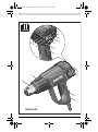 3
3
-
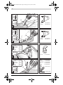 4
4
-
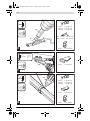 5
5
-
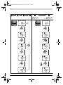 6
6
-
 7
7
-
 8
8
-
 9
9
-
 10
10
-
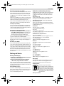 11
11
-
 12
12
-
 13
13
-
 14
14
-
 15
15
-
 16
16
-
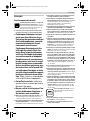 17
17
-
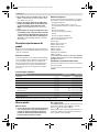 18
18
-
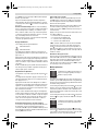 19
19
-
 20
20
-
 21
21
-
 22
22
-
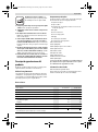 23
23
-
 24
24
-
 25
25
-
 26
26
-
 27
27
-
 28
28
-
 29
29
-
 30
30
-
 31
31
-
 32
32
-
 33
33
-
 34
34
-
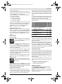 35
35
-
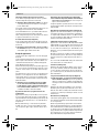 36
36
-
 37
37
-
 38
38
-
 39
39
-
 40
40
-
 41
41
-
 42
42
-
 43
43
-
 44
44
-
 45
45
-
 46
46
-
 47
47
-
 48
48
-
 49
49
-
 50
50
-
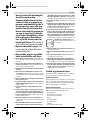 51
51
-
 52
52
-
 53
53
-
 54
54
-
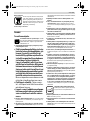 55
55
-
 56
56
-
 57
57
-
 58
58
-
 59
59
-
 60
60
-
 61
61
-
 62
62
-
 63
63
-
 64
64
-
 65
65
-
 66
66
-
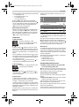 67
67
-
 68
68
-
 69
69
-
 70
70
-
 71
71
-
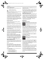 72
72
-
 73
73
-
 74
74
-
 75
75
-
 76
76
-
 77
77
-
 78
78
-
 79
79
-
 80
80
-
 81
81
-
 82
82
-
 83
83
-
 84
84
-
 85
85
-
 86
86
-
 87
87
-
 88
88
-
 89
89
-
 90
90
-
 91
91
-
 92
92
-
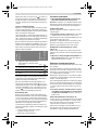 93
93
-
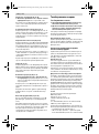 94
94
-
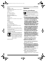 95
95
-
 96
96
-
 97
97
-
 98
98
-
 99
99
-
 100
100
-
 101
101
-
 102
102
-
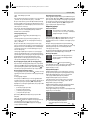 103
103
-
 104
104
-
 105
105
-
 106
106
-
 107
107
-
 108
108
-
 109
109
-
 110
110
-
 111
111
-
 112
112
-
 113
113
-
 114
114
-
 115
115
-
 116
116
-
 117
117
-
 118
118
-
 119
119
-
 120
120
-
 121
121
-
 122
122
-
 123
123
-
 124
124
-
 125
125
-
 126
126
-
 127
127
-
 128
128
-
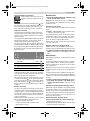 129
129
-
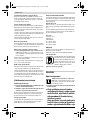 130
130
-
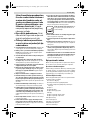 131
131
-
 132
132
-
 133
133
-
 134
134
-
 135
135
-
 136
136
-
 137
137
-
 138
138
-
 139
139
-
 140
140
-
 141
141
-
 142
142
-
 143
143
-
 144
144
-
 145
145
-
 146
146
-
 147
147
-
 148
148
-
 149
149
-
 150
150
-
 151
151
-
 152
152
-
 153
153
-
 154
154
-
 155
155
-
 156
156
-
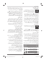 157
157
-
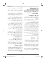 158
158
-
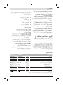 159
159
-
 160
160


Bosch LCD Professional Manualul utilizatorului
- Tip
- Manualul utilizatorului
în alte limbi
- slovenčina: Bosch LCD Professional Užívateľská príručka
Lucrări conexe
-
Bosch GHG 23-66 Manual de utilizare
-
Bosch GHG 660 LCD Specificație
-
Bosch GHG 600 CE Manual de utilizare
-
Bosch GHG 20-63 Manual de utilizare
-
-
-
-
-
Bosch GRB 14 CE Manual de utilizare
-
Alte documente
-
Skil 8007 MA Manual de utilizare
-
Skil 8004 AA Manual de utilizare
-
-
Skil 8003 CA Manual de utilizare
-
Tryton THL2000C Manual de utilizare
-
Hitachi RH 650V Handling Instructions Manual
-
STEINEL SN-348311 Manualul proprietarului
-
Defort DHG-2000N-K Manualul proprietarului
-
Bort BHG-2000L-K Manual de utilizare
-
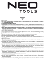 NEO TOOLS 21-004 Manualul proprietarului
