
Robert Bosch Power Tools GmbH
70538 Stuttgart
GERMANY
www.bosch-pt.com
1 609 92A 4UE (2019.02) T / 179
de Originalbetriebsanleitung
en Original instructions
fr Notice originale
es Manual original
pt Manual original
it Istruzioni originali
nl Oorspronkelijke gebruiksaanwijzing
da Original brugsanvisning
sv Bruksanvisning i original
no Original driftsinstruks
fi Alkuperäiset ohjeet
el Πρωτότυπο οδηγιών χρήσης
tr Orijinal işletme talimatı
pl Instrukcja oryginalna
cs Původní návod k používání
sk Pôvodný návod na použitie
hu Eredeti használati utasítás
ru Оригинальное руководство по
эксплуатации
uk Оригінальна інструкція з
експлуатації
kk Пайдалану нұсқаулығының
түпнұсқасы
ro Instrucțiuni originale
bg Оригинална инструкция
mk Оригинално упатство за работа
sr Originalno uputstvo za rad
sl Izvirna navodila
hr Originalne upute za rad
et Algupärane kasutusjuhend
lv Instrukcijas oriģinālvalodā
lt Originali instrukcija
ko 사용 설명서 원본
ar
fa
1 609 92A 4UE
GHG Professional
20-63 | 23-66

2 |
Deutsch ..................................................Seite 6
English ................................................... Page 11
Français.................................................. Page 16
Español ................................................ Página 22
Português .............................................. Página 28
Italiano ................................................. Pagina 33
Nederlands............................................. Pagina 38
Dansk .................................................... Side 43
Svensk .................................................. Sidan 48
Norsk..................................................... Side 53
Suomi .....................................................Sivu 58
Ελληνικά................................................ Σελίδα 63
Türkçe................................................... Sayfa 68
Polski .................................................. Strona 74
Čeština................................................ Stránka 79
Slovenčina ............................................ Stránka 84
Magyar ...................................................Oldal 89
Русский............................................. Страница 95
Українська ...........................................Сторінка 101
Қазақ ..................................................... Бет 107
Română ................................................ Pagina 112
Български .......................................... Страница 118
Македонски......................................... Страница 123
Srpski .................................................. Strana 129
Slovenščina ..............................................Stran 134
Hrvatski ...............................................Stranica 139
Eesti.................................................. Lehekülg 144
Latviešu .............................................. Lappuse 149
Lietuvių k. .............................................Puslapis 154
............................................... 159
.................................................. 165
.................................................. 171
.......................................................... I
1 609 92A 4UE | (04.02.2019) Bosch Power Tools

| 3
P
P
P
P
P
P
P
P
P
P
P
P
P
P
P
P
PP
P
P
P
P
P
P
P
P
P
P
P
P
P
P
P
P
P
P
P
P
P
P
P
P
P
P
P
P
GHG 23-66 GHG 20-63
(1) (2)
(3)
(4)
(3)
(4)
(4)
(5)
(6)
(7)
(8)
(9)
(10)
(11)
(12)
(13)
(6)
(7)
(12)
(13)
Bosch Power Tools 1 609 92A 4UE | (04.02.2019)

4 |
75 mm 1 609 390 451
50 mm 1 609 201 795
75 mm 1 609 390 452
50 mm 1 609 201 796
H2O
80 mm
1 609 201 751
(14)
(15)
(16)
A
B
C
1 609 92A 4UE | (04.02.2019) Bosch Power Tools

| 5
32 mm
1 609 390 453
HDPE 1 609 201 807
PVC (hard) 1 609 201 808
PVC (soft) 1 609 201 809
PP 1 609 201 810
1 609 201 798
1 609 201 797
80 mm 1 609 201 751
Ø 9 mm 1 609 201 797
Ø 14mm 1 609 201 647
Ø 20 mm 1 609 201 648
32 mm 1 609 390 453
Ø 1,6
–
4,8 mm 1 609 201 812
Ø 4,8
–
9,5 mm 1 609 201 813
Ø Ø
32 mm
1 609 390 453
Ø
(17)
(18)
(19)
(20)
(17)
(21)
(20)
D
E
F
G
Bosch Power Tools 1 609 92A 4UE | (04.02.2019)

6 | Deutsch
Deutsch
Sicherheitshinweise
Lesen Sie alle Sicherheitshinweise und An-
weisungen. Versäumnisse bei der Einhaltung
der Sicherheitshinweise und Anweisungen
können elektrischen Schlag, Brand und/oder
schwere Verletzungen verursachen.
Bewahren Sie alle Sicherheitshinweise und Anweisungen
für die Zukunft auf.
uDieses Heißluftgebläse ist nicht
vorgesehen für die Benutzung
durch Kinder und Personen mit
eingeschränkten physischen, sen-
sorischen oder geistigen Fähigkei-
ten oder mangelnder Erfahrung
und Wissen. Dieses Heißluftgeblä-
se kann von Kindern ab 8 Jahren
und Personen mit eingeschränk-
ten physischen, sensorischen oder
geistigen Fähigkeiten oder man-
gelnder Erfahrung und Wissen be-
nutzt werden, wenn sie durch eine
für ihre Sicherheit verantwortliche
Person beaufsichtigt werden oder
von dieser im sicheren Umgang
mit dem Heißluftgebläse eingewie-
sen worden sind und die damit ver-
bundenen Gefahren verstehen.
Andernfalls besteht die Gefahr von
Fehlbedienung und Verletzungen.
uBeaufsichtigen Sie Kinder bei Be-
nutzung, Reinigung und Wartung.
Damit wird sichergestellt, dass Kin-
der nicht mit dem Heißluftgebläse
spielen.
uGehen Sie sorgsam mit dem
Elektrowerkzeug um. Das Elektro-
werkzeug erzeugt starke Hitze, die zu
erhöhter Brand- und Explosionsge-
fahr führt.
uSeien Sie besonders vorsichtig, wenn Sie in der Nähe
brennbarer Materialien arbeiten. Der heiße Luftstrom
bzw. die heiße Düse können Staub oder Gase entzünden.
uArbeiten Sie mit dem Elektrowerkzeug nicht in explo-
sionsgefährdeter Umgebung.
uRichten Sie den heißen Luftstrom nicht für längere
Zeit auf ein und dieselbe Stelle. Leicht entzündliche Ga-
se können z.B. bei der Bearbeitung von Kunststoffen, Far-
ben, Lacken oder ähnlichen Materialien entstehen.
uBeachten Sie, dass Wärme zu verdeckten brennbaren
Materialien geleitet werden und diese entzünden
kann.
uLegen Sie das Elektrowerkzeug nach Gebrauch sicher
ab und lassen Sie es vollständig auf den Ablageflächen
auskühlen, bevor Sie es wegpacken. Die heiße Düse
kann Schaden anrichten.
uLassen Sie das eingeschaltete Elektrowerkzeug nicht
unbeaufsichtigt.
uBewahren Sie unbenutzte Elektrowerkzeuge außer-
halb der Reichweite von Kindern auf. Lassen Sie Per-
sonen das Elektrowerkzeug nicht benutzen, die mit
diesem nicht vertraut sind oder diese Anweisungen
nicht gelesen haben. Elektrowerkzeuge sind gefahrlich,
wenn sie von unerfahrenen Personen benutzt werden.
uHalten Sie das Elektrowerkzeug von Regen oder Nässe
fern. Das Eindringen von Wasser in ein Elektrowerkzeug
erhöht das Risiko eines elektrischen Schlages.
uZweckentfremden Sie das Kabel nicht, um das
Elektrowerkzeug zu tragen, aufzuhängen oder um den
Stecker aus der Steckdose zu ziehen. Halten Sie das
Kabel fern von Hitze oder Öl. Beschädigte oder verwickel-
te Kabel erhöhen das Risiko eines elektrischen Schlages.
uTragen Sie immer eine Schutzbrille. Eine Schutzbrille
verringert das Risiko von Verletzungen.
uZiehen Sie den Stecker aus der Steckdose, bevor Sie
Geräteeinstellungen vornehmen, Zubehörteile wech-
seln oder das Elektrowerkzeug weglegen. Diese Vor-
sichtsmaßnahme verhindert den unbeabsichtigten Start
des Elektrowerkzeuges.
uÜberprüfen Sie vor jeder Benutzung Elektrowerkzeug,
Kabel und Stecker. Benutzen Sie das Elektrowerkzeug
nicht, sofern Sie Schäden feststellen. Öffnen Sie das
Elektrowerkzeug nicht selbst und lassen Sie es nur
von qualifiziertem Fachpersonal und nur mit Original-
Ersatzteilen reparieren. Beschädigte Elektrowerkzeuge,
Kabel und Stecker erhöhen das Risiko eines elektrischen
Schlages.
1 609 92A 4UE | (04.02.2019) Bosch Power Tools

Deutsch | 7
Belüften Sie Ihren Arbeitsplatz gut. Beim Ar-
beiten entstehende Gase und Dämpfe sind
häufig gesundheitsschädlich.
uTragen Sie Schutzhandschuhe und berühren Sie die
heiße Düse nicht. Es besteht Verbrennungsgefahr.
uRichten Sie den heißen Luftstrom nicht auf Personen
oder Tiere.
uVerwenden Sie das Elektrowerkzeug nicht als Haar-
trockner. Der austretende Luftstrom ist wesentlich hei-
ßer als bei einem Haartrockner.
uAchten Sie darauf, dass keine Fremdkörper in das
Elektrowerkzeug gelangen.
uDer Abstand der Düse zum Werkstück richtet sich
nach dem zu bearbeitenden Material (Metall, Kunst-
stoff etc.) und beabsichtigter Bearbeitungsart. Ma-
chen Sie immer erst einen Test bezüglich Luftmenge und
Temperatur.
uWenn der Betrieb des Elektrowerkzeugs in feuchter
Umgebung nicht vermeidbar ist, verwenden Sie einen
Fehlerstromschutzschalter. Der Einsatz eines Fehler-
stromschutzschalters vermindert das Risiko eines elektri-
schen Schlages.
uBenutzen Sie das Elektrowerkzeug nicht mit beschä-
digtem Kabel. Berühren Sie das beschädigte Kabel
nicht und ziehen Sie den Netzstecker, wenn das Kabel
während des Arbeitens beschädigt wird. Beschädigte
Kabel erhöhen das Risiko eines elektrischen Schlages.
Produkt- und
Leistungsbeschreibung
Bitte beachten Sie die Abbildungen im vorderen Teil der Be-
triebsanleitung.
Bestimmungsgemäßer Gebrauch
Das Elektrowerkzeug ist bestimmt zum Verformen und Ver-
schweißen von Kunststoff, Entfernen von Farbanstrichen
und zum Erwärmen von Schrumpfschläuchen. Es ist auch ge-
eignet zum Löten und Verzinnen, Lösen von Klebeverbindun-
gen und zum Auftauen von Wasserleitungen.
Das Elektrowerkzeug ist zum handgeführten, beaufsichtigten
Gebrauch bestimmt.
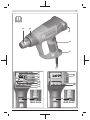
Abgebildete Komponenten
Die Nummerierung der abgebildeten Komponenten bezieht
sich auf die Darstellung des Elektrowerkzeuges auf der
Grafikseite.
(1) Düse
(2) Wärmeschutz, abnehmbar
(3) Ablagefläche
(4) Ein-/Ausschalter und Leistungsstufen
(5) Speicherplatz
(6) Temperatur
(7) Thermoschutzabschaltung
(8) Lüftersymbol
(9) Luftmenge
(10) Lüftertaste
(11) Speichertaste
(12) Taste +/–
(13) Display
(14) FlächendüseA)
(15) GlasschutzdüseA)
(16) WinkeldüseA)
(17) ReflektordüseA)
(18) SchweißdrahtA)
(19) SchweißschuhA)
(20) ReduzierdüseA)
(21) SchrumpfschlauchA)
A) Abgebildetes oder beschriebenes Zubehör gehört nicht zum
Standard-Lieferumfang. Das vollständige Zubehör finden
Sie in unserem Zubehörprogramm.
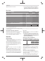
Technische Daten
Heißluftgebläse GHG 20-63 GHG 23-66
Sachnummer 3 601 BA6 2.. 3 601 BA6 3..
Nennaufnahmeleistung W 2000 2100 (2300A))
Luftmenge l/min 150/150–300/
300–500 150–300/
150–500
Temperatur am DüsenausgangB) °C 50–630 50–650
Temperatur-Messgenauigkeit
– am Düsenausgang ±10 % ±10 %
– in der Anzeige ±5 % ±5 %
Betriebstemperatur DisplayC) °C 0...+50 0...+50
max. zulässige Umgebungstemperatur bei Betrieb °C 40 40
Gewicht entsprechend EPTA-Procedure 01:2014 kg 0,65 0,67
Bosch Power Tools 1 609 92A 4UE | (04.02.2019)

8 | Deutsch
Heißluftgebläse GHG 20-63 GHG 23-66
Schutzklasse / /
A) maximal mögliche Leistungsaufnahme
B) bei 20 °C Umgebungstemperatur, ca.
C) Außerhalb der Betriebstemperatur kann das Display schwarz werden.
Die Angaben gelten für eine Nennspannung [U] von 230 V. Bei abweichenden Spannungen und in länderspezifischen Ausführungen können diese
Angaben variieren.
Geräusch-/Vibrationsinformation
Der A-bewertete Schalldruckpegel des Elektrowerkzeugs ist
typischerweise kleiner als 70dB(A).
Schwingungsgesamtwerte ah (Vektorsumme dreier Richtun-
gen) und Unsicherheit K: ah≤2,5m/s2, K=1,5m/s2.
Betrieb
Inbetriebnahme
uBeachten Sie die Netzspannung! Die Spannung der
Stromquelle muss mit den Angaben auf dem Typenschild
des Elektrowerkzeuges ubereinstimmen.
Rauchentwicklung bei der ersten Inbetriebnahme
Ab Werk sind die Metalloberflächen mit einer Beschichtung
vor Korrosion geschützt. Diese Schutzschicht verdampft bei
der ersten Inbetriebnahme.
Einschalten
Schieben Sie den Ein-/Ausschalter(4) nach oben.
Thermoschutzabschaltung: Bei Überhitzung (z.B. durch
Luftstau) schaltet das Elektrowerkzeug die Heizung automa-
tisch ab, das Gebläse läuft jedoch weiter. Hat sich das
Elektrowerkzeug auf Betriebstemperatur abgekühlt, wird die
Heizung automatisch wieder zugeschaltet.
Ausschalten
Schieben Sie den Ein-/Ausschalter(4) nach unten in Stel-
lung0.
uLassen Sie das Elektrowerkzeug nach längerem Arbei-
ten mit hoher Temperatur vor dem Ausschalten ab-
kühlen. Lassen Sie es dafür für kurze Zeit mit der nied-
rigsten einstellbaren Temperatur laufen.
Luftmenge regeln (GHG20‑63)
Mit dem Ein-/Ausschalter(4) können Sie die Luftmenge in
verschiedenen Stufen regeln:
Luftmengenstufe l/min °C
150 50
150–300 50–630
300–500 50–630
Die Angaben gelten für eine Nennspannung [U] von 230 V. Bei abwei-
chenden Spannungen und in länderspezifischen Ausführungen kön-
nen diese Angaben variieren.
Verringern Sie die Luftmenge z.B. dann, wenn die Umgebung
eines Werkstücks nicht übermäßig erhitzt werden soll oder
wenn sich ein leichtes Werkstück durch den Luftstrom ver-
schieben könnte.
Temperatur regeln (GHG20‑63)
In der niedrigsten Luftmengenstufe ist die Temperatur auf
50°C festgelegt. In den beiden anderen Luftmengenstufen
ist die Temperatur regelbar.
Mit dem Wechsel von der niedrigsten Luftmengenstufe in ei-
ne andere Stufe wird die dort zuletzt eingestellte Temperatur
wieder aufgerufen.
Um die Temperatur zu erhöhen, drücken Sie an der Tas-
te(12) auf +, um die Temperatur zu senken, drücken Sie
auf –.
Kurzes Drücken der Taste(12) erhöht bzw. senkt die Tem-
peratur um 10°C. Längeres Drücken der Taste erhöht bzw.
senkt die Temperatur fortlaufend um 10°C, bis die Taste los-
gelassen wird oder die maximale bzw. minimale Temperatur
erreicht ist.
Die eingestellte Soll-Temperatur wird 3 Sekunden lang im
Display angezeigt. Bis die Soll-Temperatur erreicht ist, wird
die tatsächliche Temperatur am Düsenausgang angezeigt
und die Maßeinheit der Temperatur(6) blinkt. Ist die Soll-
Temperatur erreicht, blinkt die Maßeinheit der Temperatur
nicht mehr.
uReduzieren Sie die Temperatur, dauert es kurze Zeit,
bis sich das Elektrowerkzeug abgekühlt hat.
Die niedrigste Luftmengenstufe ist geeignet zum Abkühlen
eines erhitzten Werkstücks oder zum Trocknen von Farbe.
Sie ist ebenso geeignet, um das Elektrowerkzeug vor dem
Abstellen oder dem Wechsel der Aufsatzdüsen abzukühlen.
Luftmenge regeln (GHG23‑66)
In Schalterstellung 1 des Ein-/Ausschalters(4) können Sie
die Luftmenge in zehn Schritten zwischen 150 und 300 l/
min einstellen. In Schalterstellung 2 können Sie die Luftmen-
ge in zehn Schritten zwischen 150 und 500 l/min einstellen.
Alternativ können Sie abgespeicherte Luftmenge-/Tempera-
turkombinationen nutzen (siehe „Luftmenge-/Temperatur-
kombinationen abspeichern (GHG 23-66)“, Seite9).
Die eingestellte Luftmenge wird mit den zehn Balkenseg-
menten(9) am unteren Displayrand gezeigt.
Schalter-
stellung l/min °C
1150–300 50
2150–500 50–650
Um die Luftmenge zu regeln, drücken Sie zunächst die Lüf-
tertaste(10). Das Lüftersymbol(8) im Display blinkt. Nun
können Sie mit der Taste(12) die Luftmenge einstellen.
1 609 92A 4UE | (04.02.2019) Bosch Power Tools

Deutsch | 9
Um die Luftmenge zu erhöhen, drücken Sie an der Tas-
te(12) auf +, um die Luftmenge zu senken, drücken Sie
auf –.
Wenn Sie mit der Taste(12) wieder die Temperatur einstel-
len wollen, drücken Sie erneut auf die Lüftertaste(10). Das
Lüftersymbol(8) im Display blinkt nicht mehr.
Wenn Sie von Schalterstellung 1 in Stellung 2 schalten, wird
die zuletzt in Stellung 2 genutzte Luftmenge-/Temperatur-
kombination eingestellt.
Verringern Sie die Luftmenge z.B. dann, wenn die Umgebung
eines Werkstücks nicht übermäßig erhitzt werden soll oder
wenn sich ein leichtes Werkstück durch den Luftstrom ver-
schieben könnte.
Temperatur regeln (GHG23‑66)
In Schalterstellung 1 des Ein-/Ausschalters(4) ist die Tem-
peratur auf 50°C fixiert. In Schalterstellung 2 können Sie die
Temperatur zwischen 50 und 650°C einstellen.
Alternativ können Sie abgespeicherte Luftmenge-/Tempera-
turkombinationen nutzen (siehe „Luftmenge-/Temperatur-
kombinationen abspeichern (GHG 23-66)“, Seite9).
Die eingestellte Temperatur wird im Display(13) gezeigt.
Schalter-
stellung °C l/min
150 150–300
250–650 150–500
Um die Temperatur zu erhöhen, drücken Sie an der Tas-
te(12) auf +, um die Temperatur zu senken, drücken Sie auf
–.
Kurzes Drücken der Taste(12) erhöht bzw. senkt die Tem-
peratur um 10°C. Längeres Drücken der Taste erhöht bzw.
senkt die Temperatur fortlaufend um 10 °C, bis die Taste los-
gelassen wird oder die maximale bzw. minimale Temperatur
erreicht ist.
Die eingestellte Soll-Temperatur wird 3 Sekunden lang im
Display angezeigt. Bis die Soll-Temperatur erreicht ist, wird
die tatsächliche Temperatur am Düsenausgang angezeigt
und die Maßeinheit der Temperatur(6) blinkt. Ist die Soll-
Temperatur erreicht, blinkt die Maßeinheit der Temperatur
nicht mehr.
uReduzieren Sie die Temperatur, dauert es kurze Zeit,
bis sich das Elektrowerkzeug abgekühlt hat.
Die Schalterstellung 1 ist geeignet zum Abkühlen eines er-
hitzten Werkstücks oder zum Trocknen von Farbe. Sie ist
ebenso geeignet, um das Elektrowerkzeug vor dem Abstellen
oder dem Wechsel der Aufsatzdüsen abzukühlen.
Luftmenge-/Temperaturkombinationen abspeichern
(GHG 23-66)
Sie können vier Luftmenge-/Temperaturkombinationen ab-
speichern oder auf vier ab Werk gespeicherte Kombinatio-
nen zugreifen.
Hierzu muss der Ein-/Ausschalter(4) auf Schalterstellung 2
stehen.
Werkseinstellung
Speicher-
platz °C l/min Anwendung
0A) 50 150 – Werkstück abkühlen
– Farbe trocknen
1 250 350 Kunststoffrohre verformen
2 350 400 Kunststoff verschweißen
3 450 500 Lack entfernen
4 550 400 Weichlöten
A) wird nicht im Display angezeigt
Um eine Kombination abzurufen, drücken Sie die Speicher-
taste(11) so oft, bis die gewünschte Nummer in der Anzei-
ge(5) erscheint.
Eigene Kombination speichern:
– Wählen Sie durch Drücken der Speichertaste(11) den
gewünschten Speicherplatz aus.
– Stellen Sie die gewünschte Temperatur und Luftmenge
ein. Der Speicherplatz(5) blinkt, um anzuzeigen, dass die
gespeicherte Kombination geändert wurde.
– Drücken Sie Speichertaste(11) und halten Sie sie ge-
drückt. Der Speicherplatz(5) blinkt für etwa 2Sekunden.
Sobald er dauerhaft leuchtet, ist die neue Kombination
gespeichert.
Arbeitshinweise
uZiehen Sie vor allen Arbeiten am Elektrowerkzeug den
Netzstecker aus der Steckdose.
Hinweis: Bringen Sie die Düse(1) nicht zu nah an das zu be-
arbeitende Werkstück. Der entstehende Luftstau kann zur
Überhitzung des Elektrowerkzeugs führen.
Wärmeschutz abnehmen
Für Arbeiten an besonders engen Stellen können Sie den
Wärmeschutz(2) durch Drehen abnehmen.
uVorsicht vor der heißen Düse! Bei Arbeiten ohne Wär-
meschutz besteht erhöhte Verbrennungsgefahr.
Zum Abnehmen bzw. Aufsetzen des Wärmeschutzes(2)
schalten Sie das Elektrowerkzeug aus und lassen es abküh-
len.
Zum schnelleren Abkühlen können Sie das Elektrowerkzeug
auch kurz mit der niedrigsten einstellbaren Temperatur lau-
fen lassen.
Elektrowerkzeug abstellen
Stellen Sie das Elektrowerkzeug auf den Ablageflächen(3)
ab, um es abkühlen zu lassen oder um beide Hände zum Ar-
beiten frei zu haben.
uArbeiten Sie mit dem abgestellten Elektrowerkzeug
besonders vorsichtig! Sie können sich an der heißen Dü-
se oder am heißen Luftstrom verbrennen.
Positionieren Sie das Elektrowerkzeug auf einer ebenen, sta-
bilen Fläche. Stellen Sie sicher, dass es nicht umkippen
kann. Sichern Sie das Kabel außerhalb Ihres Arbeitsberei-
ches so, dass es das Elektrowerkzeug nicht umwerfen oder
herunterziehen kann.
Bosch Power Tools 1 609 92A 4UE | (04.02.2019)

10 | Deutsch
Schalten Sie das Elektrowerkzeug bei längerem Nichtge-
brauch aus und ziehen Sie den Netzstecker.
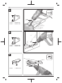
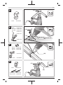
Arbeitsbeispiele (sieheBilderA–G)
Die Abbildungen der Arbeitsbeispiele finden Sie auf den
Grafikseiten.
Der Abstand der Düse zum Werkstück richtet sich nach dem
zu bearbeitenden Material (Metall, Kunststoff etc.) und der
beabsichtigten Bearbeitungsart.
Die optimale Temperatur für die jeweilige Anwendung lässt
sich durch praktischen Versuch ermitteln.
Machen Sie immer erst einen Test bezüglich Luftmenge und
Temperatur. Beginnen Sie mit einem größeren Abstand und
einer niedrigen Leistungsstufe. Passen Sie Abstand und
Leistungsstufe dann nach Bedarf an.
Wenn Sie sich nicht sicher sind, welches Material Sie bear-
beiten oder wie die Wirkung der Heißluft auf das Material ist,
dann testen Sie die Wirkung an einer verdeckten Stelle.
Sie können bei allen Arbeitsbeispielen außer „Lack von Fens-
terrahmen entfernen“ ohne Zubehör arbeiten. Der Einsatz
der vorgeschlagenen Zubehörteile vereinfacht jedoch die Ar-
beit und erhöht die Qualität des Ergebnisses wesentlich.
uVorsicht beim Düsenwechsel! Berühren Sie die heiße
Düse nicht. Lassen Sie das Elektrowerkzeug abkühlen
und tragen Sie beim Wechsel Schutzhandschuhe. Sie
können sich an der heißen Düse verbrennen.
Zum schnelleren Abkühlen können Sie das Elektrowerkzeug
auch kurz mit der niedrigsten einstellbaren Temperatur lau-
fen lassen.
Lack entfernen/Kleber lösen (sieheBildA)
Setzen Sie die Flächendüse(14) (Zubehör) auf. Weichen
Sie den Lack kurz mit Heißluft auf und heben Sie ihn mit ei-
nem sauberen Spachtel ab. Lange Hitzeeinwirkung ver-
brennt den Lack und erschwert das Entfernen.
Viele Klebemittel werden durch Wärme weich. Bei erwärm-
tem Kleber können Sie Verbindungen trennen oder über-
schüssigen Kleber entfernen.
Lack von Fensterrahmen entfernen (sieheBildB)
uVerwenden Sie unbedingt die Glasschutzdüse (15)
(Zubehör). Es besteht Glasbruchgefahr.
Auf profilierten Flächen können Sie den Lack mit einem pas-
senden Spachtel abheben und mit einer weichen Drahtbürs-
te abbürsten.
Wasserleitungen auftauen (sieheBildC)
uPrüfen Sie vor dem Erwärmen, ob es sich tatsächlich
um eine Wasserleitung handelt. Wasserleitungen sind
oft äußerlich nicht von Gasleitungen zu unterscheiden.
Gasleitungen dürfen keinesfalls erwärmt werden.
Setzen Sie die Winkeldüse(16) (Zubehör) auf. Erwärmen
Sie eingefrorene Stellen vorzugsweise vom Ablauf in Rich-
tung Zulauf.
Erwärmen Sie Kunststoffrohre sowie Verbindungen zwi-
schen Rohrstücken besonders vorsichtig, um Beschädigun-
gen zu vermeiden.
Kunststoffrohre verformen (sieheBildD)
Setzen Sie die Reflektordüse(17) (Zubehör) auf. Füllen Sie
Kunststoffrohre mit Sand und verschließen Sie sie auf bei-
den Seiten, um das Abknicken des Rohres zu verhindern. Er-
wärmen Sie das Rohr vorsichtig und gleichmäßig durch seitli-
ches Hin- und Herbewegen.
Kunststoff verschweißen (sieheBildE)
Setzen Sie die Reduzierdüse(20) und den Schweiß-
schuh(19) (beide Zubehör) auf. Die zu verschweißenden
Werkstücke und der Schweißdraht(18) (Zubehör) müssen
aus dem gleichen Material sein (z.B. beide PVC). Die Naht
muss sauber und fettfrei sein.
Erwärmen Sie die Nahtstelle vorsichtig, bis sie teigig wird.
Beachten Sie, dass der Temperaturbereich zwischen teigi-
gem und flüssigem Zustand eines Kunststoffes gering ist.
Führen Sie den Schweißdraht(18) zu und lassen Sie ihn in
den Spalt einlaufen, sodass eine gleichmäßige Wulst ent-
steht.
Weichlöten (siehe Bild F)
Setzen Sie für Punktlötungen die Reduzierdüse (20), für das
Löten von Rohren die Reflektordüse(17) (beide Zubehör)
auf.
Falls Sie Lot ohne Flussmittel verwenden, geben Sie Lötfett
oder Lötpaste auf die Lötstelle. Erwärmen Sie die Lötstelle je
nach Material ca. 50 bis 120Sekunden. Geben Sie das Lot
zu. Das Lot muss durch die Werkstücktemperatur schmel-
zen.
Entfernen Sie gegebenenfalls nach dem Erkalten der Lotstel-
le das Flussmittel.
Schrumpfen (sieheBildG)
Setzen Sie die Reflektordüse(17) (Zubehör) auf. Wählen
Sie den Durchmesser des Schrumpfschlauches(21) (Zube-
hör) passend zum Werkstück. Erwärmen Sie den Schrumpf-
schlauch gleichmäßig, bis er eng am Werkstück anliegt.
Wartung und Service
Wartung und Reinigung
uZiehen Sie vor allen Arbeiten am Elektrowerkzeug den
Netzstecker aus der Steckdose.
uHalten Sie das Elektrowerkzeug und die Lüftungs-
schlitze sauber, um gut und sicher zu arbeiten.
Wenn ein Ersatz der Anschlussleitung erforderlich ist, dann
ist dies von Bosch oder einer autorisierten Kundendienst-
stelle für Bosch-Elektrowerkzeuge auszuführen, um Sicher-
heitsgefährdungen zu vermeiden.
Kundendienst und Anwendungsberatung
Der Kundendienst beantwortet Ihre Fragen zu Reparatur und
Wartung Ihres Produkts sowie zu Ersatzteilen. Explosions-
zeichnungen und Informationen zu Ersatzteilen finden Sie
auch unter: www.bosch-pt.com
Das Bosch-Anwendungsberatungs-Team hilft Ihnen gerne
bei Fragen zu unseren Produkten und deren Zubehör.
1 609 92A 4UE | (04.02.2019) Bosch Power Tools

English | 11
www.powertool-portal.de, das Internetportal für Handwer-
ker und Heimwerker.
Geben Sie bei allen Rückfragen und Ersatzteilbestellungen
bitte unbedingt die 10-stellige Sachnummer laut Typen-
schild des Produkts an.
Deutschland
Robert Bosch Power Tools GmbH
Servicezentrum Elektrowerkzeuge
Zur Luhne 2
37589 Kalefeld – Willershausen
Unter www.bosch-pt.de können Sie online Ersatzteile be-
stellen oder Reparaturen anmelden.
Kundendienst: Tel.: (0711) 40040460
Fax: (0711) 40040461
E-Mail: [email protected]
Anwendungsberatung:
Tel.: (0711) 40040460
Fax: (0711) 40040462
E-Mail: [email protected]
Österreich
Unter www.bosch-pt.at können Sie online Ersatzteile bestel-
len.
Tel.: (01) 797222010
Fax: (01) 797222011
E-Mail: [email protected]
Schweiz
Unter www.bosch-pt.com/ch/de können Sie online Ersatz-
teile bestellen.
Tel.: (044) 8471511
Fax: (044) 8471551
E-Mail: [email protected]
Luxemburg
Tel.: +32 2 588 0589
Fax: +32 2 588 0595
E-Mail: [email protected]
Entsorgung
Elektrowerkzeuge, Zubehör und Verpackungen sollen einer
umweltgerechten Wiederverwertung zugeführt werden.
Werfen Sie Elektrowerkzeuge nicht in den
Hausmüll!
Nur für EU-Länder:
Gemaß der Europaischen Richtlinie 2012/19/EU uber Elek-
tro- und Elektronik-Altgerate und ihrer Umsetzung in natio-
nales Recht mussen nicht mehr gebrauchsfahige Elektro-
werkzeuge getrennt gesammelt und einer umweltgerechten
Wiederverwertung zugefuhrt werden.
English
Safety instructions
Read all the safety information and instruc-
tions. Failure to observe the safety informa-
tion and follow instructions may result in elec-
tric shock, fire and/or serious injury.
Save all warnings and instructions for future reference.
uThis heat gun is not intended for
use by children or persons with
physical, sensory or mental limita-
tions or a lack of experience or
knowledge. This heat gun can be
used by children aged 8 or older
and by persons who have physical,
sensory or mental limitations or a
lack of experience or knowledge if
a person responsible for their
safety supervises them or has in-
structed them in the safe opera-
tion of the heat gun and they un-
derstand the associated dangers.
Otherwise there is a risk of operating
errors and injury.
uSupervise children during use,
cleaning and maintenance. This will
ensure that children do not play with
the heat gun.
uHandle the power tool with care.
The power tool produces intense
heat which increases the risk of fire
and explosion.
uTake particular care when working in the vicinity of
flammable materials. The hot airflow or hot nozzle may
ignite dust or gases.
uDo not work with the power tool in potentially explos-
ive areas.
Bosch Power Tools 1 609 92A 4UE | (04.02.2019)

12 | English
uDo not aim the hot airflow at the same area for pro-
longed periods. Working with plastic, paint, varnish or
similar materials may produce easily flammable gases.
uPlease be aware that heat is directed to covered flam-
mable materials, which may ignite.
uSafely place the power tool on the storage surfaces
after use and let it cool completely before packing it
away. The hot nozzle can cause damage.
uDo not leave the switched-on power tool unattended.
uStore idle power tools out of the reach of children. Do
not allow persons unfamiliar with the power tool or
these instructions to operate the power tool. Power
tools are dangerous in the hands of untrained users.
uDo not expose the power tool to rain or wet condi-
tions. Water entering a power tool will increase the risk of
electric shock.
uDo not misuse the cable, for example by using it to
carry, hang up or unplug the power tool. Keep the cable
away from heat and oil. Damaged or entangled cords in-
crease the risk of electric shock.
uAlways wear safety goggles. Safety goggles reduce the
risk of injury.
uPull the plug out of the socket before adjusting the
tool settings, changing accessories, or storing the
power tool. Such preventive safety measures reduce the
risk of starting the power tool accidentally.
uAlways check the power tool, cable and plug before
use. Stop using the power tool if you discover any
damage. Do not open the power tool yourself, and
have it repaired only by a qualified specialist using
only original replacement parts. Damaged power tools,
cables and plugs increase the risk of electric shock.
Keep your work area well-ventilated. The
gas and steam produced during work are often
harmful to one's health.
uWear protective gloves and do not touch the nozzle
while it is hot. There is a risk of burns.
uDo not direct the airflow at persons or animals.
uDo not use the power tool as a hair dryer. The outgoing
airflow is considerably hotter than that that of a hair
dryer.
uDo not allow foreign objects to enter the power tool.
uThe distance between the nozzle and the workpiece
depends on the material you are working on (metal,
plastic, etc.) and the intended working method. Al-
ways test the amount of air and temperature first.
uIf operating the power tool in a damp location is un-
avoidable, use a residual current device (RCD) protec-
ted supply. Use of an RCD reduces the risk of electric
shock.
uNever use the power tool if the cable is damaged. Do
not touch the damaged cable and pull out the mains
plug if the cable is damaged while working. Damaged
cables increase the risk of an electric shock.
Products sold in GB only:
Your product is fitted with an BS 1363/A approved electric
plug with internal fuse (ASTA approved to BS 1362).
If the plug is not suitable for your socket outlets, it should be
cut off and an appropriate plug fitted in its place by an au-
thorised customer service agent. The replacement plug
should have the same fuse rating as the original plug.
The severed plug must be disposed of to avoid a possible
shock hazard and should never be inserted into a mains
socket elsewhere.
Product Description and
Specifications
Please observe the illustrations at the beginning of this oper-
ating manual.
Intended Use
The power tool is intended for bending and welding plastic,
stripping coats of paint and heating shrink tubing. It is also
suitable for soldering and tinning, melting adhesive bonding
and thawing water pipes.
The power tool is intended to be operated by hand, under
supervision.
Product Features
The numbering of the product features refers to the diagram
of the power tool on the graphics page.
(1) Nozzle
(2) Heat shield, removable
(3) Storage surface
(4) On/off switch and power settings
(5) Memory preset
(6) Temperature
(7) Thermal protection shutdown
(8) Fan symbol
(9) Airflow
(10) Fan button
(11) Memory button
(12) +/– button
(13) Display
(14) Surface nozzleA)
(15) Glass protection nozzleA)
(16) Angle nozzleA)
(17) Reflector nozzleA)
(18) Welding wireA)
(19) Welding shoeA)
(20) Reducing nozzleA)
(21) Heat shrink plastic tubeA)
A) Accessories shown or described are not included with the
product as standard. You can find the complete selection of
accessories in our accessories range.
1 609 92A 4UE | (04.02.2019) Bosch Power Tools

English | 13
Technical Data
Heat gun GHG 20-63 GHG 23-66
Article number 3 601 BA6 2.. 3 601 BA6 3..
Rated power input W 2000 2100 (2300A))
Airflow l/min 150/150–300/
300–500 150–300/
150–500
Temperature at the nozzle outletB) °C 50–630 50–650
Temperature measurement accuracy
– at the nozzle outlet ±10% ±10%
– on the display ±5% ±5%
Operating temperature of displayC) °C 0 to +50 0 to +50
Max. permissible ambient temperature during operation °C 40 40
Weight according to EPTA-Procedure 01:2014 kg 0.65 0.67
Protection class / /
A) Maximum possible input power
B) At an ambient temperature of approx. 20°C
C) The display may go blank if outside the operating temperature.
The specifications apply to a rated voltage [U] of 230 V. These specifications may vary at different voltages and in country-specific models.
Noise/vibration information
Typically, the A-weighted sound pressure level of the power
tool is less than 70dB(A).
Vibration total values ah (triax vector sum) and uncertainty K:
ah≤2.5m/s2, K=1.5m/s2.
Operation
Starting Operation
uPay attention to the mains voltage. The voltage of the
power source must match the voltage specified on the
rating plate of the power tool.
Creation of Smoke During Initial Use
A coating protects the metal surfaces from corrosion ex-
works. This protective layer evaporates during initial use.
Switching On
Slide the on/off switch (4) upwards.
Thermal protection shutdown: If the power tool overheats
(e.g. due to a build-up of air), the heating system will auto-
matically switch off, though the blower will continue to run.
Once the power tool has cooled back down to its operating
temperature, the heating system will automatically switch on
again.
Switching Off
Slide the on/off switch(4) downwards into the0position.
uAfter working at high temperatures for a prolonged
period, let the power tool cool down before switching
it off. To do this, allow it to run on the lowest temper-
ature setting for a short while.
Regulating airflow (GHG20-63)
With the on/off switch(4), you can set the airflow to one of
several different levels:
Airflow setting l/min °C
150 50
150–300 50–630
300–500 50–630
The specifications apply to a rated voltage [U] of 230 V. These spe-
cifications may vary at different voltages and in country-specific mod-
els.
Reduce the airflow, for instance, if the area surrounding a
workpiece cannot tolerate excessive heat or if a workpiece is
light enough that the airflow might move it.
Regulating temperature (GHG20-63)
On the lowest airflow setting, the temperature is set to
50°C. In the other two airflow settings, the temperature can
be adjusted.
When switching from the lowest airflow setting to another
setting, the temperature last set is called up again.
To increase the temperature, press + on the (12)button; to
decrease the temperature, press −.
Briefly pressing the (12)button increases or decreases the
temperature by 10C. Pressing and holding down the button
continuously increases or decreases the temperature by
10°C until the button is released or the maximum/minimum
temperature is reached.
The set target temperature is shown in the display for three
seconds. The actual temperature at the nozzle output is dis-
played and the unit of measure for the temperature(6)
flashes until the target temperature is reached. The unit of
measure for the temperature stops flashing once the target
temperature is reached.
Bosch Power Tools 1 609 92A 4UE | (04.02.2019)

14 | English
uIf you reduce the temperature, it takes a little while
for the power tool to cool down.
The lowest airflow setting is suitable for cooling down a
heated workpiece or for drying paint. It is also suitable for
cooling down the power tool before putting it down or chan-
ging the attachment nozzles.
Regulating airflow (GHG23-66)
In switch position 1 on the on/off switch(4), you can adjust
the airflow in ten increments between 150 and 300l/min. In
switch position 2, you can adjust the airflow in ten incre-
ments between 150 and 500l/min.
Alternatively, you can used the saved airflow/temperature
combinations (see "Saving airflow/temperature combina-
tions (GHG 23-66)", page14).
The set airflow is displayed with the ten bar segments(9) at
the lower edge of the display.
Switch position l/min °C
1150–300 50
2150–500 50–650
To adjust the airflow, first press the fan button(10). The fan
symbol(8) in the display flashes. The airflow can now be
regulated with the airflow control button(12).
To increase the airflow, press + on the (12)button; to de-
crease the airflow, press −.
If you wish to adjust the temperature again using the
(12)button, press the fan button(10) again. The fan sym-
bol(8) in the display stops flashing.
If you move from switch position 1 to position 2, the airflow/
temperature combination last used in position 2 is set.
Reduce the airflow, for instance, if the area surrounding a
workpiece cannot tolerate excessive heat or if a workpiece is
light enough that the airflow might move it.
Regulating temperature (GHG23-66)
In switch position 1 on the on/off switch(4), the temperat-
ure is fixed at 50°C. In switch position 2, you can adjust the
temperature between 50 and 650°C.
Alternatively, you can used the saved airflow/temperature
combinations (see "Saving airflow/temperature combina-
tions (GHG 23-66)", page14).
The set temperature is shown in the display(13).
Switch position °C l/min
150 150–300
250–650 150–500
To increase the temperature, press + on the (12)button; to
decrease the temperature, press −.
Briefly pressing the (12)button increases or decreases the
temperature by 10°C. Pressing and holding down the button
continuously increases or decreases the temperature by
10°C until the button is released or the maximum/minimum
temperature is reached.
The set target temperature is shown in the display for three
seconds. The actual temperature at the nozzle output is dis-
played and the unit of measure for the temperature(6)
flashes until the target temperature is reached. The unit of
measure for the temperature stops flashing once the target
temperature is reached.
uIf you reduce the temperature, it takes a little while
for the power tool to cool down.
Switch setting 1 is suitable for cooling down a heated work-
piece or for drying paint. It is also suitable for cooling down
the power tool before putting it down or changing the attach-
ment nozzles.
Saving airflow/temperature combinations (GHG 23-66)
You can save four airflow/temperature combinations or ac-
cess four saved preset combinations.
To do this, the on/off switch(4) must be set to switch posi-
tion 2.
Factory settings
Memory
preset °C l/min Application
0A) 50 150 – Cooling down a workpiece
– Drying paint
1 250 350 Shaping plastic pipes
2 350 400 Welding plastic
3 450 500 Removing varnish
4 550 400 Soft soldering
A) Not shown in the display
To call up a combination, keep pressing the memory button
(11) until the number you want appears in the display (5).
To save your own combination:
– Press the memory button(11) to select the memory pre-
set you want.
– Set the desired temperature and airflow. The memory
preset(5) flashes to indicate that the saved combination
has been changed.
– Press and hold down the memory button(11). The
memory preset(5) flashes for around two seconds. When
it lights up continuously, the new combination has been
saved.
Practical advice
uPull the plug out of the socket before carrying out any
work on the power tool.
Note: Do not position the nozzle(1) too close to the work-
piece that you are using the power tool on. The resulting
build-up of air can cause the power tool to overheat.
Removing the heat shield
When working in particularly tight spaces, you can remove
the heat shield(2) by turning it.
uCaution: Nozzle is hot! Working without the heat shield
increases the risk of burns.
Always switch the power tool off and allow it to cool before
removing or attaching the heat shield(2).
1 609 92A 4UE | (04.02.2019) Bosch Power Tools

English | 15
To make the power tool cool down quicker, you can also let it
run briefly on its lowest temperature setting.
Setting down the power tool
Set the power tool down on the storage surfaces(3) to leave
it to cool down or to keep both hands free to work with.
uTake particular care when working in the vicinity of
the power tool while it has been set aside. The heat
from the nozzle or the air flow can cause burns.
Position the power tool on an even, stable surface. Ensure
that it cannot tip over. Secure the cable outside of your
working area so that it cannot pull the power tool down or
cause it to flip over.
Switch the power tool off when not in use for a long period
and pull the mains plug out of the socket.
Example applications (seefiguresA–G)
Images of example applications can be found on the graphics
pages.
The distance between the nozzle and the workpiece de-
pends on the material you are working on (metal, plastic
etc.) and the intended working method.
The optimum temperature for each application can be de-
termined by a practical test.
Always test the amount of air and temperature first. Start at
a greater distance and a lower power setting. Then adjust
the distance and power setting according to requirements.
If you are unsure what material you are working on or what
effect the hot air might have on it, first test the effect on a
concealed area.
All example applications apart from "Stripping paint from
window frames" can be carried out without the use of ac-
cessories. However, using the recommended accessories
will simplify the work and considerably increase the quality
of the result.
uTake care when changing the nozzle. Do not touch the
nozzle while it is hot. Leave the power tool to cool
down before changing the nozzle, and wear protective
gloves when doing so. The heat from the nozzle can
cause burns.
To make the power tool cool down quicker, you can also let it
run briefly on its lowest temperature setting.
Removing varnish/loosening adhesives(see figureA)
Fit the surface nozzle(14) (accessory). Briefly soften the
varnish with hot air and remove it with a clean spatula. Long
heat exposure burns the varnish and makes removal more
difficult.
Many adhesives can be softened using heat. By heating ad-
hesives, you can break connections or remove excess adhes-
ive.
Stripping paint from window frames (seefigureB)
uThe glass protection nozzle (15) (accessory) must be
used for this application. There is a risk that the glass
may break.
You can remove the paint from profiled surfaces with a suit-
able spatula and brush it off with a soft wire brush.
Thawing frozen water pipes (see figureC)
uBefore applying heat to the pipe, check it is in fact a
water pipe. Water pipes and gas pipes often look
identical from the outside. Gas pipes must under no cir-
cumstances be heated.
Fit the angle nozzle(16) (accessory). Gradually heat the
frozen points of the pipe, starting at the outlet and moving
back towards the inlet.
Take great care when warming plastic pipes and pipe con-
nections to avoid causing damage.
Shaping plastic pipes (see figureD)
Fit the reflector nozzle(17) (accessory). Fill plastic pipes
with sand and seal them on both sides to prevent the pipe
bending. Carefully and evenly heat the pipe by moving the
tool back and forth from one side to the other.
Welding plastic (see figureE)
Fit the reducing nozzle (20) and the welding shoe(19) (both
accessories). The workpiece requiring welding and the weld-
ing wire(18) (accessory) must be made from the same ma-
terial (e.g. both PVC). The seam must be clean and free from
grease.
Heat the point of the seam carefully until it becomes pliable.
Note that there is not a great difference in temperature
between pliable plastic and liquid plastic.
Apply the welding wire(18) and allow it to flow into the joint
to form an even bead.
Soft Soldering (see figure F)
For spot welding, fit the reducing nozzle (20); for welding
pipes, fit the reflector nozzle(17) (both accessories).
If you are using solder without flux, apply soldering grease or
paste to the solder joint. Depending on the material, heat the
solder joint for approx. 50 to 120seconds. Apply the solder.
The solder must be melted by the temperature of the work-
piece.
If necessary, remove the flux after the solder joint has cooled
down.
Heat-shrinking (see figureG)
Fit the reflector nozzle(17) (accessory). Choose the dia-
meter of the heat shrink plastic tube (21) (accessory) suit-
able for the workpiece. Evenly heat the heat shrink plastic
tube until it fits closely against the workpiece.
Maintenance and Servicing
Maintenance and Cleaning
uPull the plug out of the socket before carrying out any
work on the power tool.
uTo ensure safe and efficient operation, always keep
the power tool and the ventilation slots clean.
In order to avoid safety hazards, if the power supply cord
needs to be replaced, this must be done by Bosch or by an
after-sales service centre that is authorised to repair Bosch
power tools.
Bosch Power Tools 1 609 92A 4UE | (04.02.2019)

16 | Français
After-Sales Service and Application Service
Our after-sales service responds to your questions concern-
ing maintenance and repair of your product as well as spare
parts. You can find explosion drawings and information on
spare parts at: www.bosch-pt.com
The Bosch product use advice team will be happy to help you
with any questions about our products and their accessor-
ies.
In all correspondence and spare parts orders, please always
include the 10‑digit article number given on the nameplate
of the product.
Great Britain
Robert Bosch Ltd. (B.S.C.)
P.O. Box 98
Broadwater Park
North Orbital Road
Denham Uxbridge
UB 9 5HJ
At www.bosch-pt.co.uk you can order spare parts or arrange
the collection of a product in need of servicing or repair.
Tel. Service: (0344) 7360109
E-Mail: [email protected]
Ireland
Origo Ltd.
Unit 23 Magna Drive
Magna Business Park
City West
Dublin 24
Tel. Service: (01) 4666700
Fax: (01) 4666888
Australia, New Zealand and Pacific Islands
Robert Bosch Australia Pty. Ltd.
Power Tools
Locked Bag 66
Clayton South VIC 3169
Customer Contact Center
Inside Australia:
Phone: (01300) 307044
Fax: (01300) 307045
Inside New Zealand:
Phone: (0800) 543353
Fax: (0800) 428570
Outside AU and NZ:
Phone: +61 3 95415555
www.bosch-pt.com.au
www.bosch-pt.co.nz
Republic of South Africa
Customer service
Hotline: (011) 6519600
Gauteng – BSC Service Centre
35 Roper Street, New Centre
Johannesburg
Tel.: (011) 4939375
Fax: (011) 4930126
E-mail: [email protected]
KZN – BSC Service Centre
Unit E, Almar Centre
143 Crompton Street
Pinetown
Tel.: (031) 7012120
Fax: (031) 7012446
E-mail: [email protected]
Western Cape – BSC Service Centre
Democracy Way, Prosperity Park
Milnerton
Tel.: (021) 5512577
Fax: (021) 5513223
E-mail: [email protected]
Bosch Headquarters
Midrand, Gauteng
Tel.: (011) 6519600
Fax: (011) 6519880
E-mail: [email protected]
Disposal
The power tool, accessories and packaging should be re-
cycled in an environmentally friendly manner.
Do not dispose of power tools along with
household waste.
Only for EU countries:
According to the European Directive 2012/19/EU on Waste
Electrical and Electronic Equipment and its implementation
into national law, power tools that are no longer usable must
be collected separately and disposed of in an environment-
ally friendly manner.
Français
Consignes de sécurité
Lisez attentivement toutes les instructions
et consignes de sécurité. Le non-respect des
instructions et consignes de sécurité peut pro-
voquer un choc électrique, un incendie et/ou
entraîner de graves blessures.
Conservez tous les avertissements et toutes les instruc-
tions pour pouvoir s’y reporter ultérieurement.
uCe décapeur thermique n’est pas
prévu pour être utilisé par des en-
fants ni par des personnes souf-
frant d’un handicap physique, sen-
1 609 92A 4UE | (04.02.2019) Bosch Power Tools

Français | 17
soriel ou mental ou manquant d’ex-
périence ou de connaissances. Ce
décapeur thermique peut être uti-
lisé par des enfants (âgés d’au
moins 8ans) et par des personnes
souffrant d’un handicap physique,
sensoriel ou mental ou manquant
d’expérience ou de connaissances,
à condition qu’ils soient sous la
surveillance d’une personne res-
ponsable de leur sécurité ou après
avoir reçu des instructions sur la
façon d’utiliser le décapeur ther-
mique en toute sécurité et après
avoir bien compris les dangers in-
hérents à son utilisation. Il y a si-
non risque de blessures et d’utilisa-
tion inappropriée.
uNe laissez pas les enfants sans sur-
veillance lors de l’utilisation, du
nettoyage et de l’entretien. Faites
en sorte que les enfants ne jouent
pas avec le décapeur thermique.
uManiez l’outil électroportatif avec
précaution. L’outil électroportatif
génère des températures élevées
susceptibles de provoquer des in-
cendies ou des explosions.
uSoyez extrêmement vigilant lors d’une utilisation à
proximité de matériaux inflammables. L’air chaud et la
buse brûlante peuvent enflammer de la poussière ou des
gaz.
uN’utilisez pas l’outil électroportatif dans un environne-
ment potentiellement explosif.
uNe dirigez pas l’air chaud sur un même endroit pen-
dant une durée prolongée.Lors d’une utilisation sur des
matières plastiques, des peintures, des laques ou
d’autres matériaux similaires, des gaz facilement inflam-
mables pourraient être générés.
uAyez à l’esprit que la chaleur peut se propager vers
des matériaux inflammables cachés et les enflammer.
uAprès son utilisation, posez l’outil électroportatif sur
un support stable et laissez-le refroidir complètement
sur ses surfaces d’appui avant de le ranger.La buse
chaude peut causer des dommages.
uNe pas laisser l’outil électroportatif mis en marche
sans surveillance.
uConservez les outils inutilisés hors de la portée des
enfants. Ne laissez pas des personnes, qui ne
connaissent pas l’outil ou qui n’ont pas lues la pré-
sente notice, utiliser l’outil électroportatif. Les outils
sont dangereux entre les mains d’utilisateurs novices.
uN’exposez pas l’outil électroportatif à la pluie ou à
l’humidité. La pénétration d’eau à l’intérieur d’un outil
électroportatif augmente le risque de choc électrique.
uNe maltraitez pas le cordon d’alimentation. Ne vous en
servez pas pour porter, accrocher l’outil électroporta-
tif et ne tirez pas dessus pour débrancher l’outil de la
prise secteur. N’exposez pas l’outil électroportatif à la
pluie ou à l’humidité. Les cordons endommagés ou em-
mêlés augmentent le risque de choc électrique.
uPortez toujours des lunettes de protection. Des lu-
nettes de protection réduisent le risque de blessures.
uDébranchez le connecteur de la prise avant tout ré-
glage, changement d’accessoire ou avant de ranger
l’outil électroportatif.De telles mesures de sécurité pré-
ventives réduisent le risque de démarrage accidentel de
l’outil électroportatif.
uAvant chaque utilisation, vérifiez l’état de l’outil élec-
troportatif, de son cordon d’alimentation et de son
connecteur. N’utilisez plus l’outil électroportatif si
vous constatez des dommages. N’ouvrez pas l’outil
électroportatif vous-même. Ne confiez sa réparation
qu’à un réparateur qualifié utilisant uniquement des
pièces de rechange d’origine. En cas de défectuosité de
l’outil électroportatif, de son cordon d’alimentation ou
connecteur, le risque de choc électrique augmente.
Aérez bien le poste de travail. Les gaz et va-
peurs générés en cours d’utilisation sont sou-
vent nuisibles à la santé.
uPortez des gants de protection et ne touchez pas la
buse chaude. Il y a risque de brûlure.
uNe dirigez pas l’air chaud vers des personnes ou des
animaux.
uN’utilisez pas l’outil électroportatif comme sèche-che-
veux. L’air qui sort est beaucoup plus chaud que celui
d’un sèche-cheveux.
uVeillez à ce qu’aucun corps étranger ne pénètre dans
l’outil électroportatif.
uLa distance à respecter entre la buse et la pièce dé-
pend de la nature du matériau (métal, plastique, etc.)
et de la nature du travail à effectuer. Commencez tou-
jours par effectuer des tests pour bien choisir le débit
d’air et la température.
uSi l’usage de l’outil électroportatif dans un environne-
ment humide est inévitable, intercalez un disjoncteur
Bosch Power Tools 1 609 92A 4UE | (04.02.2019)

18 | Français
différentiel. L’utilisation d’un disjoncteur différentiel ré-
duit le risque de choc électrique.
uN’utilisez jamais un outil électroportatif dont le câble
est endommagé. Ne touchez pas le câble endommagé
et débranchez aussitôt le câble de la prise au cas où
celui-ci est endommagé pendant l’utilisation de l’outil.
Un câble endommagé augmente le risque de choc élec-
trique.
Description des prestations et du
produit
Référez-vous aux illustrations qui se trouvent au début de la
notice d’utilisation.
Utilisation conforme
L’outil électroportatif est conçu pour les travaux de déforma-
tion et de soudage de matières plastiques, d’enlèvement de
couches de peinture ainsi que pour le réchauffement de
gaines thermorétractables. Il peut aussi être utilisé pour bra-
ser et étamer, défaire des liaisons collées et pour dégeler
des canalisations d’eau.
L’outil électroportatif est destiné à une utilisation à main le-
vée, sous surveillance.
Éléments constitutifs
La numérotation des éléments de l’appareil se réfère à la re-
présentation de l’outil électroportatif sur la page graphique.
(1) Buse
(2) Protection thermique, amovible
(3) Surface d’appui
(4) Interrupteur marche/arrêt et positions de tempéra-
ture
(5) Emplacement mémoire
(6) Température
(7) Désactivation de la protection thermique
(8) Symbole soufflerie
(9) Débit d’air
(10) Touche soufflerie
(11) Touche de mémorisation
(12) Touche +/–
(13) Écran
(14) Buse plateA)
(15) Buse protège-vitreA)
(16) Buse coudéeA)
(17) Buse à réflecteurA)
(18) Baguette de soudageA)
(19) Patin de soudageA)
(20) Buse de réductionA)
(21) Gaine thermorétractableA)
A) Les accessoires décrits ou illustrés ne sont pas tous compris
dans la fourniture. Vous trouverez les accessoires complets
dans notre gamme d’accessoires.
Caractéristiques techniques
Décapeur thermique GHG 20-63 GHG 23-66
Référence 3 601 BA6 2.. 3 601 BA6 3..
Puissance absorbée nominale W 2000 2100 (2300A))
Débit d’air l/min 150/150–300/
300–500 150–300/
150–500
Température à l’extrémité de la buseB) °C 50–630 50–650
Précision de mesure de la température
– à la sortie de la buse ±10% ±10%
– à l’affichage ±5% ±5%
Températures de fonctionnement de l’écranC) °C 0...+50 0...+50
Température ambiante maximale admissible en cours de
fonctionnement °C 40 40
Poids selon EPTA-Procedure 01:2014 kg 0,65 0,67
Indice de protection / /
A) Puissance absorbée maximale possible
B) à une température ambiante de 20°C, env.
C) Il est possible que l’écran devienne noir en dehors de la plage de températures normales.
Les données indiquées sont valables pour une tension nominale [U] de 230 V. Elles peuvent varier lorsque la tension diffère de cette valeur et sur
les versions destinées à certains pays.
Informations sur le niveau sonore / les vibrations
La mesure réelle (A) du niveau de pression acoustique de
l’outil est en général inférieur à 70dB(A).
Valeurs globales de vibration ah (somme vectorielle sur les
trois axes) et incertitude K: ah≤2,5m/s2, K=1,5m/s2.
1 609 92A 4UE | (04.02.2019) Bosch Power Tools

Français | 19
Utilisation
Mise en marche
uTenez compte de la tension secteur ! La tension du sec-
teur doit correspondre aux indications se trouvant sur la
plaque signalétique de l’outil électroportatif.
Dégagement de fumée lors de la première utilisation
Un revêtement est appliqué en usine sur les surfaces métal-
liques pour les protéger de la corrosion. Cette couche de
protection s’évapore lors de la première utilisation.
Mise en marche
Poussez l’interrupteur marche/arrêt (4) vers le haut.
Arrêt de sécurité thermique : En cas de surchauffe (causée
par ex. par une accumulation d’air chaud), l’outil électropor-
tatif arrête automatiquement le chauffage mais la soufflerie
continue de fonctionner. Une fois que l’outil électroportatif a
suffisamment refroidi, le chauffage se réactive automatique-
ment.
Arrêt
Poussez l’interrupteur marche/arrêt (4) vers le bas jusque
dans la position 0.
uAprès une utilisation prolongée à température élevée,
laissez refroidir l’outil électroportatif avant de l’arrê-
ter. Laissez-le pour cela fonctionner pendant une
courte durée à la plus basse température réglable.
Réglage du débit d’air (GHG 20-63)
L’interrupteur marche/arrêt (4) permet de régler différentes
positions de débit d’air :
Position de débit d’air l/min °C
150 50
150–300 50–630
300–500 50–630
Les données indiquées sont valables pour une tension nominale [U]
de 230 V. Elles peuvent varier lorsque la tension diffère de cette va-
leur et sur les versions destinées à certains pays.
Réduisez le débit d’air par ex. quand il ne faut pas que les
abords de la pièce deviennent trop chauds ou quand le
souffle d’air risque de déplacer la pièce.
Réglage de la température (GHG 20-63)
Dans la position de débit d’air minimal, la température est
fixée à 50°C. Dans les deux autres positions de débit d’air, la
température est réglable.
Lors du passage de la position de débit d’air minimal à l’une
des deux autres positions, la température réglée en dernier
est rappelée.
Pour augmenter la température, actionnez le côté + de la
touche (12) ; pour réduire la température, actionnez le côté
– de la touche.
Une brève pression sur la touche (12) augmente ou diminue
la température de 10°C. Une pression prolongée sur la
touche augmente ou réduit la température en continu par
pas de 10°C, jusqu’à ce que la touche soit relâchée ou que la
température minimale ou maximale soit atteinte.
La consigne de température réglée s’affiche pendant 3se-
condes. Tant que la température de consigne n’est pas at-
teinte, la température réelle à la sortie de la buse est affichée
et l’unité de température (6) clignote. Une fois que la tempé-
rature de consigne est atteinte, l’unité de température cesse
de clignoter.
uLorsque vous réduisez la température, l’outil électro-
portatif met quelque temps à refroidir.
La position de débit d’air inférieure est idéale pour refroidir
une pièce chaude ou sécher de la peinture. Elle peut aussi
être sélectionnée pour refroidir l’outil électroportatif avant
de le ranger ou de changer de buse.
Réglage du débit d’air (GHG 23-66)
Dans la position 1 de l’interrupteur marche/arrêt (4), le dé-
bit d’air peut être réglé en dix paliers, de 150 à 300l/min.
Dans la position 2, le débit d’air peut être réglé en dix pa-
liers, de 150 à 500l/min.
Sinon, vous pouvez utiliser les combinaisons débit d’air/tem-
pérature (voir « Mémorisation de combinaisons débit d’air/
température (GHG 23-66) », Page20).
Le débit d’air réglé s’affiche au bas de l’écran à l’aide de dix
barres (9).
Position de
l’interrupteur l/min °C
1150–300 50
2150–500 50–650
Pour modifier le débit d’air, actionnez d’abord la touche
soufflerie (10). Le symbole soufflerie (8) se met à clignoter
à l’écran. Le débit d’air se règle ensuite avec la touche (12).
Pour augmenter le débit d'air, actionnez le côté + de la
touche (12) ; pour réduire le débit d'air, actionnez le côté –
de la touche.
Pour revenir au réglage de température avec la touche (12),
actionnez à nouveau la touche soufflerie (10). Le symbole
soufflerie (8) cesse de clignoter à l’écran.
Si vous passez de la position 1 à la position 2 de l’interrup-
teur, la dernière combinaison débit d’air/température utili-
sée dans la position 2 est automatiquement activée.
Réduisez le débit d’air par ex. quand il ne faut pas que les
abords de la pièce deviennent trop chauds ou quand le
souffle d’air risque de déplacer la pièce.
Réglage de la température (GHG 23-66)
Dans la position 1 de l’interrupteur marche/arrêt (4), la tem-
pérature est fixée à 50°C. Dans la position 2 de l’interrup-
teur, la température peut être réglée entre 50 et 650°C.
Sinon, vous pouvez utiliser les combinaisons débit d’air/tem-
pérature (voir « Mémorisation de combinaisons débit d’air/
température (GHG 23-66) », Page20).
La température réglée s’affiche sur l’écran (13).
Bosch Power Tools 1 609 92A 4UE | (04.02.2019)

20 | Français
Position de
l’interrupteur °C l/min
150 150–300
250–650 150–500
Pour augmenter la température, actionnez le côté + de la
touche (12) ; pour réduire la température, actionnez le côté
– de la touche.
Une brève pression sur la touche (12) augmente ou diminue
la température de 10°C. Une pression prolongée sur la
touche augmente ou réduit la température en continu par
pas de 10°C, jusqu’à ce que la touche soit relâchée ou que la
température minimale ou maximale soit atteinte.
La consigne de température réglée s’affiche pendant 3se-
condes. Tant que la température de consigne n’est pas at-
teinte, la température réelle à la sortie de la buse est affichée
et l’unité de température (6) clignote. Une fois que la tempé-
rature de consigne est atteinte, l’unité de température cesse
de clignoter.
uLorsque vous réduisez la température, l’outil électro-
portatif met quelque temps à refroidir.
La position 1 de l’interrupteur est idéale pour refroidir une
pièce chaude ou sécher de la peinture. Elle peut aussi être
sélectionnée pour refroidir l’outil électroportatif avant de le
ranger ou de changer de buse.
Mémorisation de combinaisons débit d’air/température
(GHG 23-66)
Vous pouvez mémoriser quatre combinaisons débit d’air/
température ou bien utiliser les quatre combinaisons préré-
glées en usine.
Pour cela, l’interrupteur marche/arrêt (4) doit se trouver
dans la position 2.
Réglages usine
Emplace-
ment
mémoire
°C l/min Application
0A) 50 150 – Refroidissement d’une pièce
– Séchage de peinture
1 250 350 Cintrage de tuyaux en plastique
2 350 400 Soudage de matières plas-
tiques
3 450 500 Enlèvement de vernis
4 550 400 Brasage tendre
A) n’est pas affiché à l’écran
Pour rappeler une combinaison, actionnez de façon répétée
la touche mémoire (11) jusqu’à ce que le numéro d’emplace-
ment mémoire souhaité (5) apparaisse à l’écran.
Mémorisation d’une combinaison personnelle :
– Sélectionnez l’emplacement mémoire souhaité en action-
nant la touche mémoire (11).
– Réglez la température et le débit d’air souhaités. L’empla-
cement mémoire (5) clignote pour signaler que la combi-
naison jusqu’ici mémorisée a été modifiée.
– Appuyez sur la touche mémoire (11) et maintenez-la en-
foncée. L’emplacement mémoire (5) clignote pendant
env. 2 secondes. Le passage à un allumage continu de
l’emplacement mémoire indique que la nouvelle combi-
naison a été mémorisée avec succès.
Instructions d’utilisation
uDébranchez le câble d’alimentation de la prise avant
d’effectuer des travaux quels qu’il soient sur l’outil
électroportatif.
Remarque : N’approchez pas trop la buse(1) de la pièce à
travailler. L’air chaud qui s’accumule risque de provoquer
une surchauffe de l’outil électroportatif.
Retrait de la protection thermique
Pour travailler dans des endroits particulièrement exigus, il
est possible de retirer la protection thermique (2) en la tour-
nant.
uAttention à la buse chaude ! Il y a risque élevé de brû-
lures pendant les travaux sans protection thermique.
Pour retirer et remettre en place la protection thermique
(2), arrêtez l’outil électroportatif et laissez-le refroidir.
Pour que l’outil électroportatif refroidisse plus rapidement,
faites-le fonctionner pendant une courte durée à la plus
basse température réglable.
Pose de l’outil électroportatif sur une surface
Posez l’outil électroportatif sur les surfaces d’appui (3) pour
le laisser refroidir ou pour avoir les deux mains libres pour
travailler.
uSoyez extrêmement prudent lorsque vous travaillez
avec l’outil électroportatif posé sur une surface ! La
buse brûlante et l’air chaud soufflé peuvent causer des
brûlures.
Placez l’outil électroportatif sur une surface stable et plane.
Assurez-vous qu’il ne risque pas de basculer. Attachez le
câble en dehors de la zone de travail pour qu’il ne puisse pas
renverser l’outil électroportatif ou le tirer vers le bas.
Arrêtez l’outil électroportatif et débranchez le câble d’ali-
mentation de la prise secteur si vous savez qu’il ne vas pas
être utilisé pendant une longue durée.
Exemples d’utilisation (voir les figuresA–G)
Vous trouverez les figures avec les exemples d’utilisation sur
les pages graphiques.
La distance à respecter entre la buse et la pièce dépend de la
nature du matériau (métal, plastique, etc.) et de la nature du
travail à effectuer.
La température optimale pour l’application envisagée doit
être déterminée en procédant à des tests pratiques.
Commencez toujours par effectuer des tests pour bien choi-
sir le débit d’air et la température. Ce faisant, commencez
avec une grande distance et avec une température basse.
Ajustez ensuite la distance et la température en fonction des
besoins.
Si vous ne connaissez pas la nature du matériau sur lequel
vous allez travailler ou ne savez pas comment le matériau va
1 609 92A 4UE | (04.02.2019) Bosch Power Tools
Pagina se încarcă...
Pagina se încarcă...
Pagina se încarcă...
Pagina se încarcă...
Pagina se încarcă...
Pagina se încarcă...
Pagina se încarcă...
Pagina se încarcă...
Pagina se încarcă...
Pagina se încarcă...
Pagina se încarcă...
Pagina se încarcă...
Pagina se încarcă...
Pagina se încarcă...
Pagina se încarcă...
Pagina se încarcă...
Pagina se încarcă...
Pagina se încarcă...
Pagina se încarcă...
Pagina se încarcă...
Pagina se încarcă...
Pagina se încarcă...
Pagina se încarcă...
Pagina se încarcă...
Pagina se încarcă...
Pagina se încarcă...
Pagina se încarcă...
Pagina se încarcă...
Pagina se încarcă...
Pagina se încarcă...
Pagina se încarcă...
Pagina se încarcă...
Pagina se încarcă...
Pagina se încarcă...
Pagina se încarcă...
Pagina se încarcă...
Pagina se încarcă...
Pagina se încarcă...
Pagina se încarcă...
Pagina se încarcă...
Pagina se încarcă...
Pagina se încarcă...
Pagina se încarcă...
Pagina se încarcă...
Pagina se încarcă...
Pagina se încarcă...
Pagina se încarcă...
Pagina se încarcă...
Pagina se încarcă...
Pagina se încarcă...
Pagina se încarcă...
Pagina se încarcă...
Pagina se încarcă...
Pagina se încarcă...
Pagina se încarcă...
Pagina se încarcă...
Pagina se încarcă...
Pagina se încarcă...
Pagina se încarcă...
Pagina se încarcă...
Pagina se încarcă...
Pagina se încarcă...
Pagina se încarcă...
Pagina se încarcă...
Pagina se încarcă...
Pagina se încarcă...
Pagina se încarcă...
Pagina se încarcă...
Pagina se încarcă...
Pagina se încarcă...
Pagina se încarcă...
Pagina se încarcă...
Pagina se încarcă...
Pagina se încarcă...
Pagina se încarcă...
Pagina se încarcă...
Pagina se încarcă...
Pagina se încarcă...
Pagina se încarcă...
Pagina se încarcă...
Pagina se încarcă...
Pagina se încarcă...
Pagina se încarcă...
Pagina se încarcă...
Pagina se încarcă...
Pagina se încarcă...
Pagina se încarcă...
Pagina se încarcă...
Pagina se încarcă...
Pagina se încarcă...
Pagina se încarcă...
Pagina se încarcă...
Pagina se încarcă...
Pagina se încarcă...
Pagina se încarcă...
Pagina se încarcă...
Pagina se încarcă...
Pagina se încarcă...
Pagina se încarcă...
Pagina se încarcă...
Pagina se încarcă...
Pagina se încarcă...
Pagina se încarcă...
Pagina se încarcă...
Pagina se încarcă...
Pagina se încarcă...
Pagina se încarcă...
Pagina se încarcă...
Pagina se încarcă...
Pagina se încarcă...
Pagina se încarcă...
Pagina se încarcă...
Pagina se încarcă...
Pagina se încarcă...
Pagina se încarcă...
Pagina se încarcă...
Pagina se încarcă...
Pagina se încarcă...
Pagina se încarcă...
Pagina se încarcă...
Pagina se încarcă...
Pagina se încarcă...
Pagina se încarcă...
Pagina se încarcă...
Pagina se încarcă...
Pagina se încarcă...
Pagina se încarcă...
Pagina se încarcă...
Pagina se încarcă...
Pagina se încarcă...
Pagina se încarcă...
Pagina se încarcă...
Pagina se încarcă...
Pagina se încarcă...
Pagina se încarcă...
Pagina se încarcă...
Pagina se încarcă...
Pagina se încarcă...
Pagina se încarcă...
Pagina se încarcă...
Pagina se încarcă...
Pagina se încarcă...
Pagina se încarcă...
Pagina se încarcă...
Pagina se încarcă...
Pagina se încarcă...
Pagina se încarcă...
Pagina se încarcă...
Pagina se încarcă...
Pagina se încarcă...
Pagina se încarcă...
Pagina se încarcă...
Pagina se încarcă...
Pagina se încarcă...
Pagina se încarcă...
Pagina se încarcă...
Pagina se încarcă...
Pagina se încarcă...
Pagina se încarcă...
-
 1
1
-
 2
2
-
 3
3
-
 4
4
-
 5
5
-
 6
6
-
 7
7
-
 8
8
-
 9
9
-
 10
10
-
 11
11
-
 12
12
-
 13
13
-
 14
14
-
 15
15
-
 16
16
-
 17
17
-
 18
18
-
 19
19
-
 20
20
-
 21
21
-
 22
22
-
 23
23
-
 24
24
-
 25
25
-
 26
26
-
 27
27
-
 28
28
-
 29
29
-
 30
30
-
 31
31
-
 32
32
-
 33
33
-
 34
34
-
 35
35
-
 36
36
-
 37
37
-
 38
38
-
 39
39
-
 40
40
-
 41
41
-
 42
42
-
 43
43
-
 44
44
-
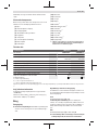 45
45
-
 46
46
-
 47
47
-
 48
48
-
 49
49
-
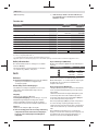 50
50
-
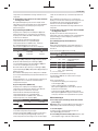 51
51
-
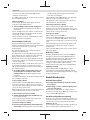 52
52
-
 53
53
-
 54
54
-
 55
55
-
 56
56
-
 57
57
-
 58
58
-
 59
59
-
 60
60
-
 61
61
-
 62
62
-
 63
63
-
 64
64
-
 65
65
-
 66
66
-
 67
67
-
 68
68
-
 69
69
-
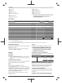 70
70
-
 71
71
-
 72
72
-
 73
73
-
 74
74
-
 75
75
-
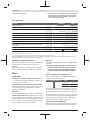 76
76
-
 77
77
-
 78
78
-
 79
79
-
 80
80
-
 81
81
-
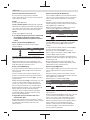 82
82
-
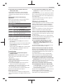 83
83
-
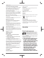 84
84
-
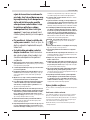 85
85
-
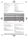 86
86
-
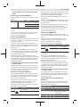 87
87
-
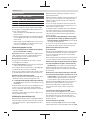 88
88
-
 89
89
-
 90
90
-
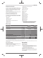 91
91
-
 92
92
-
 93
93
-
 94
94
-
 95
95
-
 96
96
-
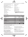 97
97
-
 98
98
-
 99
99
-
 100
100
-
 101
101
-
 102
102
-
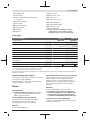 103
103
-
 104
104
-
 105
105
-
 106
106
-
 107
107
-
 108
108
-
 109
109
-
 110
110
-
 111
111
-
 112
112
-
 113
113
-
 114
114
-
 115
115
-
 116
116
-
 117
117
-
 118
118
-
 119
119
-
 120
120
-
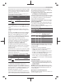 121
121
-
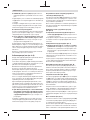 122
122
-
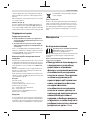 123
123
-
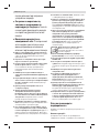 124
124
-
 125
125
-
 126
126
-
 127
127
-
 128
128
-
 129
129
-
 130
130
-
 131
131
-
 132
132
-
 133
133
-
 134
134
-
 135
135
-
 136
136
-
 137
137
-
 138
138
-
 139
139
-
 140
140
-
 141
141
-
 142
142
-
 143
143
-
 144
144
-
 145
145
-
 146
146
-
 147
147
-
 148
148
-
 149
149
-
 150
150
-
 151
151
-
 152
152
-
 153
153
-
 154
154
-
 155
155
-
 156
156
-
 157
157
-
 158
158
-
 159
159
-
 160
160
-
 161
161
-
 162
162
-
 163
163
-
 164
164
-
 165
165
-
 166
166
-
 167
167
-
 168
168
-
 169
169
-
 170
170
-
 171
171
-
 172
172
-
 173
173
-
 174
174
-
 175
175
-
 176
176
-
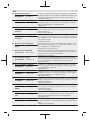 177
177
-
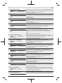 178
178
-
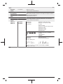 179
179


Lucrări înrudite
-
Bosch 20-63 Manual de utilizare
-
-
-
Bosch GHG 20-63 Manual de utilizare
-
-
Bosch GHG 600 CE Instrucțiuni de utilizare
-
-
Bosch PFS 105 E Manualul proprietarului
-
Bosch PFS 3000-2 Manual de utilizare