Grundfos CUE Safety Instructions And Other Important Information
- Tip
- Safety Instructions And Other Important Information

CUE
Safety instructions and other important information
GRUNDFOS INSTRUCTIONS
Installation and operating instructions
Other languages
net.grundfos.com/qr/i/96780034
Quick guide
net.grundfos.com/qr/i/96794343

English (GB)
2
English (GB)
Safety instructions and other important information
Original safety instructions
These safety instructions give a quick overview of the safety
precautions to be taken in connection with any work on this
product.
Observe these safety instructions during handling, installation,
operation, maintenance, service and repair of this product.
These safety instructions are a supplementary document, and all
safety instructions will appear again in the relevant sections of
the installation and operating instructions.
Keep these safety instructions at the installation site for future
reference.
Hazard statements
The symbols and hazard statements below may appear in
Grundfos installation and operating instructions, safety
instructions and service instructions.
The hazard statements are structured in the following way:
Notes
The symbols and notes below may appear in Grundfos
installation and operating instructions, safety instructions and
service instructions.
Intended use
CUE frequency converters can be used in both new and existing
installations. Local operation is performed via the operating panel
which has a graphic display showing the menu structure. The
menu structure uses the same system as Grundfos E-pumps.
Remote operation is performed via external signals, for instance
via digital inputs or GENIbus.
Receiving the product
Read this document and the online
version of the installation and
operating instructions before
installing the product. Installation
and operation must comply with
local regulations and accepted
codes of good practice.
DANGER
Indicates a hazardous situation
which, if not avoided, will result in
death or serious personal injury.
WARNING
Indicates a hazardous situation
which, if not avoided, could result
in death or serious personal injury.
CAUTION
Indicates a hazardous situation
which, if not avoided, could result
in minor or moderate personal
injury.
SIGNAL WORD
Description of hazard
Consequence of ignoring the warning.
- Action to avoid the hazard.
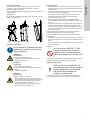
Observe these instructions for
explosion-proof products.
A blue or grey circle with a white
graphical symbol indicates that an
action must be taken.
A red or grey circle with a diagonal
bar, possibly with a black graphical
symbol, indicates that an action
must not be taken or must be
stopped.
If these instructions are not
observed, it may result in
malfunction or damage to the
equipment.
Tips and advice that make the work
easier.
WARNING
Crushing of feet
Death or serious personal injury
- Use safety shoes during transport and avoid
stacking the boxes.
CAUTION
Heavy lifting
Minor or moderate personal injury
- Use proper lifting equipment when handling the
product.
- Follow local regulations.

English (GB)
3
Inspecting the product
Check on receipt that the packaging is intact, and the unit is
complete. In case of damage during transport, contact the
transport company to complain.
Note that CUE is delivered in packaging which is not suitable for
outdoor storage.
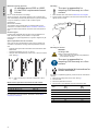
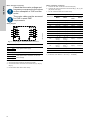
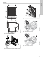
Lifting CUE
Always lift the product using the lifting holes. Use a bar to avoid
bending the lifting holes.
Fig. 1 Recommended lifting method
Installation requirements
Safety regulations
• The OFF button of the operating panel does not disconnect
CUE from the power supply and must therefore not be used as
a safety switch.
• CUE must be earthed correctly and protected against indirect
contact according to local regulations.
• The leakage current to protective earth exceeds 3.5 mA.
• Enclosure class IP20/21 must not be installed freely
accessible, but only in a panel.
• Enclosure class IP54/55 must not be installed outdoors
without additional protection against weather conditions and
the sun.
• The STO function does not disconnect CUE from the power
supply and must therefore not be used as a safety switch.
• The STO does not prevent unwanted movement from external
forces on the motor, for example, back pressure, and motor
shaft must be covered.
Always observe local regulations as to cable cross-section,
short-circuit protection and overcurrent protection.
The general safety necessitates special considerations as to
these aspects:
• fuses and switches for overcurrent and short-circuit protection
• selection of cables (mains current, motor, load distribution and
relay)
• net configuration (IT, TN, earthing) safety on connecting inputs
and outputs (PELV).
IT mains
In connection with IT mains and earthed delta mains, the mains
voltage may exceed 440 V between phase and earth.
Aggressive environment
CUE contains a large number of mechanical and electronic
components. They are all vulnerable to environmental impact.
TM03 9896 4607
Any installation, maintenance and
inspection must be carried out by
trained persons.
WARNING
Sharp element
Death or serious personal injury
- Use safety knives and protective gloves when
unpacking the product.
WARNING
Heavy lifting
Death or serious personal injury
- Use proper lifting equipment when handling the
product.
- Follow local regulations.
WARNING
Electric shock
Death or serious personal injury
- Before starting any work on the product, make
sure that the power supply has been switched off
at least for as long as stated below and that it
cannot be accidentally switched on.
- Touching the electrical parts may be fatal, even
after CUE has been switched off.
Do not connect 380-500 V CUE
frequency converters to mains
supplies with a voltage between
phase and earth of more than 440
V.
CUE must not be installed in an
environment where the air contains
liquids, particles or gases which
may affect and damage the
electronic components.

English (GB)
4
Reduction at low air pressure
PELV = Protective Extra Low Voltage.
At low air pressure, the cooling capacity of air is reduced, and
CUE automatically reduces the performance to prevent overload.
It may be necessary to select a CUE unit with a higher
performance.
Mechanical installation
The individual CUE cabinet sizes are characterised by their
enclosures. The table in section Motor connection, enclosures
shows the relationship between enclosure class and enclosure
type.
Enclosure types
Products with integrated STO function must be installed in an
IP54 cabinet according to IEC 60529 or in equivalent
environment. In special applications, a higher IP degree may be
necessary.
Space requirements and air circulation
CUE units can be mounted side by side, but as a sufficient air
circulation is required for cooling, these requirements must be
met:
• Sufficient free space above and below the CUE cabinet. See
table below.
• Ambient temperature up to 50 °C (122 °F).
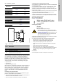
• Hang the CUE cabinet directly on the wall, or fit it with a back
plate. See fig. 2.
Fig. 2 CUE hung directly on the wall or fitted with a back
plate
Required free space above and below the CUE cabinet
For information about enclosures, see table in section Motor
connection, enclosures.
Mounting
1. Mark and drill holes. See section Dimensions and weights.
2. Fit the screws at the bottom, but leave loose. Mount CUE, and
tighten the four screws.
Fig. 3 Drilling of holes in the wall
Mounting on the floor
By means of a pedestal (optional), CUE can also be mounted on
the floor.
1. Mark the mounting holes on the floor. See fig. 1.
2. Drill the holes.
3. Mount the pedestal on the floor.
4. Mount CUE on the pedestal using the enclosed screws.
At altitudes above 2000 m (6600
ft), the PELV requirements cannot
be met.
TM03 8859 2607
Enclosure Space [mm (in)]
A2, A3, A4, A5 100 (3.9)
B1, B2, B3, B4, C1, C3 200 (7.9)
C2, C4, D1h, D2h 225 (8.9)
The user is responsible for
mounting CUE securely on a firm
surface.
TM03 8860 2607
WARNING
Crushing of feet
Death or serious personal injury
- CUE is very heavy and may fall if the pedestal is
not anchored to the floor.
The user is responsible for
mounting CUE securely on a firm
surface.
See the pedestal kit instructions for
further information.
Pos.
D1h
[mm]
D2h
[mm]
1 400 400
2 325 420
3 283.8 378.8
4 240 240
5 4 x 14 4 x 14
6 217 317
b
a
a
b

English (GB)
5
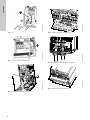
Electrical connection
Fig. 4 Example of three-phase mains connection of CUE with
main switch, backup fuses and additional protection
Protection against electric shock, indirect contact
Protection against short circuit, fuses
CUE and the supply system must be protected against short
circuit.
Grundfos demands that the backup fuses mentioned in section
Cable cross-section to signal terminals are used for protection
against short circuit.
CUE offers complete short-circuit protection in case of a short
circuit on the motor output.
Additional protection
If CUE is connected to an electrical installation where an earth
leakage circuit breaker (ELCB/RCD) is used as additional
protection, the circuit breaker must be of a type marked with the
following symbols:
The circuit breaker is type B.
The total leakage current of all the electrical equipment in the
installation must be taken into account.
The leakage current of CUE in normal operation can be seen in
the CUE installation and operating instructions.
During startup and in asymmetrical supply systems, the leakage
current can be higher than normal and may cause the ELCB/RCD
to trip.
EMC-correct installation
Fig. 5 QR code to CUE installation and operating instructions
WARNING
Electric shock
Death or serious personal injury
- Before starting any work on the product, make
sure that the power supply has been switched off
and that it cannot be accidentally switched on. See
Installation requirements.
- Touching the electrical parts may be fatal, even
after CUE has been switched off.
The owner or installer is
responsible for ensuring correct
earthing and protection according
to local standards.
For products with STO, ensure a
short-circuit protection of the cable
between terminal 37 and the
external safety device.
Security measures are the
responsibility of the user.
The frequency converter
parameters can be
password-protected.
TM03 8525 1807
ELCB/RCD
CAUTION
Electric shock
Minor or moderate personal injury
- CUE must be earthed correctly and protected
against indirect contact according to local
regulations.
The leakage current to protective
earth exceeds 3.5 mA, and a
reinforced earth connection is
required.
WARNING
Electric shock
Death or serious personal injury
- The leakage current to protective earth exceeds
3.5 mA.
The motor cable must be screened
for CUE to meet EMC
requirements.
ELCB/RCD
net.grundfos.com/qr/i/96780034

English (GB)
6
Mains and motor connection
Wiring diagram
Fig. 6 Wiring diagram, three-phase mains connection
Mains connection
1. Connect the earth conductor to terminal 95 (PE).
2. Connect the mains conductors to terminals 91 (L1), 92 (L2),
93 (L3).
3. Fix the mains cable with a cable clamp.
Motor connection, enclosures
1. Connect the earth conductor to terminal 99 (PE).
2. Connect the motor conductors to terminals 96 (U), 97 (V), 98
(W) of the motor plug.
3. Fix the screened cable with a cable clamp.
1)
Conductor cross-section ≤ 95 mm
2
( ≤ 4/0 AWG)
2)
Conductor cross-section ≥ 95 mm
2
( ≥ 4/0 AWG).
Check that the mains voltage and
frequency correspond to the values
on the nameplate of CUE and the
motor.
The motor cable must be screened
for CUE to meet EMC
requirements.
TM03 8799 2507
Terminal Function
91 (L1)
Three-phase mains supply92 (L2)
93 (L3)
95/99 (PE) Earth connection
96 (U)
Three-phase motor connection, 0-100 % of
mains voltage
97 (V)
98 (W)
Enclosure
Torque Nm [ft (lb)]
Mains Motor
Protective
earth
Relay
A2 1.8 (1.3) 1.8 (1.3) 3 (2.2) 0.6 (0.4)
A3 1.8 (1.3) 1.8 (1.3) 3 (2.2) 0.6 (0.4)
A4 1.8 (1.3) 1.8 (1.3) 3 (2.2) 0.6 (0.4)
A5 1.8 (1.3) 1.8 (1.3) 3 (2.2) 0.6 (0.4)
B1 1.8 (1.3) 1.8 (1.3) 3 (2.2) 0.6 (0.4)
B2 4.5 (3.3) 4.5 (3.3) 3 (2.2) 0.6 (0.4)
B3 1.8 (1.3) 1.8 (1.3) 3 (2.2) 0.6 (0.4)
B4 4.5 (3.3) 4.5 (3.3) 3 (2.2) 0.6 (0.4)
C1 10 (7.4) 10 (7.4) 3 (2.2) 0.6 (0.4)
C2
14
1)
/24
2)
(10.3
1)
/
17.7
2)
)
14
1)
/24
2)
(10.3
1)
/
17.7
2)
)
3 (2.2) 0.6 (0.4)
C3 10 10 3 (2.2) 0.6 (0.4)
C4
14
1)
/24
2)
(10.3
1)
/
17.7
2)
)
14
1)
/24
2)
(10.3
1)
/
17.7
2)
)
3 (2.2) 0.6 (0.4)
D1h 19-40 19-40 3 (2.2) 0.6 (0.4)
D2h 19-40 19-40 3 (2.2) 0.6 (0.4)

English (GB)
7
STO installation, optional
Fig. 7 STO wiring
Activating the optional STO function
The STO function is activated by removing the voltage at terminal
37 of the frequency converter. By connecting the frequency
converter to external safety devices providing a safe delay, an
installation for a Safe Stop 1 is obtained. External safety devices
need to fulfil Cat./PL or SIL when connected to terminal 37.
The STO function can be used for the following motor types:
• asynchronous
• synchronous
• permanent magnet motors.
When terminal 37 is activated, the frequency converter issues an
alarm, trips the unit, and coasts the motor to a stop. A manual
restart is required. Use the STO function to stop the frequency
converter in emergency stop situations. In normal operating
mode, the STO terminal 37 must be deactivated to start the
motor.
Connecting the signal terminals
Connect the signal cables according to the guidelines for good
practice to ensure EMC-correct installation.
• Use screened signal cables with a conductor cross-section of
minimum 0.5 mm
2
and maximum 1.5 mm
2
.
• Use a 3-conductor screened bus cable in new systems.
Connection of a thermistor (PTC) to CUE
The connection of a thermistor (PTC) in a motor to CUE requires
an external PTC relay.
The requirement is based on the fact that the thermistor in the
motor only has one layer of insulation to the windings. The
terminals in CUE require two layers of insulation since they are
part of a PELV circuit.
A PELV circuit provides protection against electric shock. Special
connection requirements apply to this type of circuit. The
requirements are described in EN 61800-5-1.
In order to maintain PELV, all connections made to the control
terminals must be PELV. For example, the thermistor must have
reinforced or double insulation.
Wiring diagram, MCB 114
See fig. 14 in the appendix.
Servicing the product
Conduct a functional test every 12 months to detect any failure or
malfunction of the STO functionality.
To conduct the functional test, perform the following steps:
• Remove the 24 V DC voltage supply at terminal 37.
• Check if the LCP displays the alarm Safe Stop A68.
• Verify that the frequency converter trips the unit.
• Verify that the motor is coasting and comes to a complete
stop.
• Verify that the motor cannot be started.
• Reconnect the 24 V DC voltage supply to terminal 37.
• Verify that the motor is not started automatically and restarts
only by giving a reset signal (via bus, Digital I/O, or reset
button).
Enclosures
See nameplate and install according to enclosure type.
Enclosure
Appendix
Mains Motor
A2
fig. 2 fig. 3
A3
A4
fig. 4 fig. 5
A5
B1
fig. 6 fig. 7
B2
B3 fig. 8
B4 fig. 9
C1
fig. 10
C2
C3 fig. 11
C4 fig. 12
D1h
fig. 13
D2h
TM07 4594 1919
Pos. Description
1 Reset button
2 Safety relay (cat. 3, PL d or SIL2)
3 Emergency stop button
4
Short-circuit protected cable if the product is not
installed inside an IP54 cabinet.
12
37
1
3
FC
4
2
When using Pt100 with 3-wire
cable, the resistance must not
exceed 30 Ω.
CAUTION
Electric shock
Minor or moderate personal injury
- Before starting any work on the product, make
sure that the power supply has been switched off
and that it cannot be accidentally switched on. See
Installation requirements
- Touching the electrical parts may be fatal, even
after CUE has been switched off.

English (GB)
8
Operating conditions
Cable requirements
Cable cross-section to signal terminals
Non-UL fuses and conductor cross-section to mains and
motor, for installations outside North America
1)
Screened motor cable, unscreened supply cable. AWG. See
section UL fuses and conductor cross-section to mains and
motor, for installations in North America.
Relative humidity 5-95 % RH
Ambient temperature
Max. 50 °C
(122 °F)
Average ambient temperature over 24 hours
Max. 45 °C
(113 °F)
Minimum ambient temperature at full
operation
0 °C (32 °F)
Minimum ambient temperature at reduced
operation
-10 °C (14 °F)
Temperature during storage and transport
-25 to 65 °C
(-13 to 149 °F)
Storage duration Max. 6 months
Maximum altitude above sea level without
performance reduction
1000 m (3280 ft)
Maximum altitude above sea level with
performance reduction
3000 m (9840 ft)
Maximum length, screened motor cable 150 m (500 ft)
Maximum length, unscreened motor cable 300 m (1000 ft)
Maximum length, signal cable 300 m (1000 ft)
Always comply with local
regulations as to cable
cross-sections.
Maximum cable cross-section to signal
terminals, rigid conductor
1.5 mm
2
(14 AWG)
Maximum cable cross-section to signal
terminals, flexible conductor
1.0 mm
2
(18 AWG)
Minimum cable cross-section to signal
terminals
0.5 mm
2
(20 AWG)
Typical shaft
power P2
Maximum
fuse size
Fuse
type
Maximum conductor
cross-section
1)
[kW (hp)] [A] [mm
2
]
1 x 200-240 V
1.1 (1.5) 20 gG 4
1.5 (2) 30 gG 10
2.2 (3) 40 gG 10
3 (4) 40 gG 10
3.7 (5) 60 gG 10
5.5 (7.5) 80 gG 10
7.5 (10) 100 gG 35
3 x 200-240 V
0.75 (1) 10 gG 4
1.1 (1.5) 20 gG 4
1.5 (2) 20 gG 4
2.2 (3) 20 gG 4
3 (4) 32 gG 4
3.7 (5) 32 gG 4
5.5 (7.5) 63 gG 10
7.5 (10) 63 gG 10
11 (15) 63 gG 10
15 (20) 80 gG 35
18.5 (25) 125 gG 50
22 (30) 125 gG 50
30 (40) 160 gG 50
37 (50) 200 aR 95
45 (60) 250 aR 120
3 x 380-500 V
0.55 (0.75) 10 gG 4
0.75 (1) 10 gG 4
1.1 (1.5) 10 gG 4
1.5 (2) 10 gG 4
2.2 (3) 20 gG 4
3 (4) 20 gG 4
4 (5) 20 gG 4
5.5 (7.5) 32 gG 4
7.5 (10) 32 gG 4
11 (15) 63 gG 10
15 (20) 63 gG 10
18.5 (25) 63 gG 10
22 (30) 63 gG 35
30 (40) 80 gG 35
37 (50) 100 gG 50
45 (60) 125 gG 50
55 (75) 160 gG 50
75 (100) 250 aR 95
90 (125) 250 aR 120
110 (150) 300 gG 2 × 70
132 (200) 350 gG 2 × 70
160 (250) 400 gG 2 × 185
200 (300) 500 gG 2 × 185
250 (350) 600 gR 2 × 185
3 x 525-600 V
0.75 (1) 10 gG 4
1.1 (1.5) 10 gG 4
1.5 (2) 10 gG 4
2.2 (3) 20 gG 4
3 (4) 20 gG 4
4 (5) 20 gG 4
5.5 (7.5) 32 gG 4
7.5 (10) 32 gG 4
3 x 525-690 V
11 (15) 63 gG 35
15 (20) 63 gG 35
18.5 (25) 63 gG 35
22 (30) 63 gG 35
30 (40) 63 gG 35
37 (50) 80 gG 95
45 (60) 100 gG 95
55 (75) 125 gG 95
75 (100) 160 gG 95
90 (125) 160 gG 95
110 (150) 225 - 2 × 70
132 (200) 250 - 2 × 70
160 (250) 350 - 2 × 70
200 (300) 400 - 2 × 185
250 (350) 500 - 2 × 185
Typical shaft
power P2
Maximum
fuse size
Fuse
type
Maximum conductor
cross-section
1)
[kW (hp)] [A] [mm
2
]

English (GB)
9
UL fuses and conductor cross-section to mains and motor, for installations in North America
Typical shaft
power P2
Fuse type Maximum
conductor
cross-section
1)
Bussmann
RK1/E1958/
JFHR2
Bussmann
J/E4273
T/JDDZ
Bussmann
T/E4274
H/JDDZ
SIBA RK1/
Bussmann
E125085
JFHR2
Littel Fuse
RK1/SIBA
E180276
RKI/JDDZ
Ferraz-Shawmut
CC/Littel Fuse
E71611 JFHR2
Ferraz-Shawmut
RK1/E60314 JFHR2
[kW (hp)] [AWG]
2)
1 x 200-240 V
1.1 (1.5) KTN-R20 - - - - - - 10
1.5 (2) KTN-R30 - - - - - - 7
2.2 (3) KTN-R40 - - - - - - 7
3 (4) KTN-R40 - - - - - - 7
3.7 (5) KTN-R60 - - - - - - 7
5.5 (7.5) - - - - - - - 7
7.5 (10) - - - - - - - 2
3 x 200-240 V
0.75 (1) KTN-R10 JKS-10 JJN-10 5017906-010 KTN-R10 ATM-R10 A2K-10R 10
1.1 (1.5) KTN-R20 JKS-20 JJN-20 5017906-020 KTN-R20 ATM-R20 A2K-20R 10
1.5 (2) KTN-R20 JKS-20 JJN-20 5017906-020 KTN-R20 ATM-R20 A2K-20R 10
2.2 (3) KTN-R20 JKS-20 JJN-20 5017906-020 KTN-R20 ATM-R20 A2K-20R 10
3 (4) KTN-R30 JKS-30 JJN-30 5012406-032 KTN-R30 ATM-R30 A2K-30R 10
3.7 (5) KTN-R30 JKS-30 JJN-30 5012406-032 KTN-R30 ATM-R30 A2K-30R 10
5.5 (7.5) KTN-R50 JKS-50 JJN-50 5012406-050 KLN-R50 - A2K-50R 7
7.5 (10) KTN-R50 JKS-60 JJN-60 5012406-050 KLN-R60 - A2K-50R 7
11 (15) KTN-R60 JKS-60 JJN-60 5014006-063 KLN-R60 A2K-60R A2K-60R 7
15 (20) KTN-R80 JKS-80 JJN-80 5014006-080 KLN-R80 A2K-80R A2K-80R 2
18.5 (25) KTN-R125 JKS-150 JJN-125 2028220-125 KLN-R125 A2K-125R A2K-125R 1/0
22 (30) KTN-R125 JKS-150 JJN-125 2028220-125 KLN-R125 A2K-125R A2K-125R 1/0
30 (40) FWX-150 - - 2028220-150 L25S-150 A25X-150 A25X-150 1/0
37 (50) FWX-200 - - 2028220-200 L25S-200 A25X-200 A25X-200 4/0
45 (60) FWX-250 - - 2028220-250 L25S-250 A25X-250 A25X-250 250 MCM
3 x 380-500 V
0.55 (0.75) KTS-R10 JKS-10 JJS-10 5017906-010 KTN-R10 ATM-R10 A2K-10R 10
0.75 (1) KTS-R10 JKS-10 JJS-10 5017906-010 KTN-R10 ATM-R10 A2K-10R 10
1.1 (1.5) KTS-R10 JKS-10 JJS-10 5017906-010 KTN-R10 ATM-R10 A2K-10R 10
1.5 (2) KTS-R10 JKS-10 JJS-10 5017906-010 KTN-R10 ATM-R10 A2K-10R 10
2.2 (3) KTS-R20 JKS-20 JJS-20 5017906-020 KTN-R20 ATM-R20 A2K-20R 10
3 (4) KTS-R20 JKS-20 JJS-20 5017906-020 KTN-R20 ATM-R20 A2K-20R 10
4 (5) KTS-R20 JKS-20 JJS-20 5017906-020 KTN-R20 ATM-R20 A2K-20R 10
5.5 (7.5) KTS-R30 JKS-30 JJS-30 5012406-032 KTN-R30 ATM-R30 A2K-30R 10
7.5 (10) KTS-R30 JKS-30 JJS-30 5012406-032 KTN-R30 ATM-R30 A2K-30R 10
11 (15) KTS-R40 JKS-40 JJS-40 5014006-040 KLS-R40 - A6K-40R 7
15 (20) KTS-R40 JKS-40 JJS-40 5014006-040 KLS-R40 - A6K-40R 7
18.5 (25) KTS-R50 JKS-50 JJS-50 5014006-050 KLS-R50 - A6K-50R 7
22 (30) KTS-R60 JKS-60 JJS-60 5014006-063 KLS-R60 - A6K-60R 2
30 (40) KTS-R80 JKS-80 JJS-80 2028220-100 KLS-R80 - A6K-80R 2
37 (50) KTS-R100 JKS-100 JJS-100 2028220-125 KLS-R100 - A6K-100R 1/0
45 (60) KTS-R125 JKS-150 JJS-150 2028220-125 KLS-R125 - A6K-125R 1/0
55 (75) KTS-R150 JKS-150 JJS-150 2028220-160 KLS-R150 - A6K-150R 1/0
75 (100) FWH-220 - - 2028220-200 L50S-225 - A50-P225 4/0
90 (125) FWH-250 - - 2028220-250 L50S-250 - A50-P250 250 MCM
110 (150) FWH-300 JJS-300 NOS-300 170M3017 2028220-38 L50S-300 A50-P300 2 x 2/0
132 (200) FWH-350 JJS-350 NOS-350 170M3018 2028220-38 L50S-350 A50-P350 2 x 2/0
160 (250) FWH-400 JJS-400 NOS-400 170M4012 206xx32-400 L50S-400 A50-P400 2 x 350 MCM
200 (300) FWH-500 JJS-500 NOS-500 170M4014 206xx32-500 L50S-500 A50-P500 2 x 350 MCM
250 (350) FWH-600 JJS-600 NOS-600 170M4016 206xx32-600 L50S-600 A50-P600 2 x 350 MCM
----
Bussmann
E125085
JFHR2
SIBA
E180276
JFHR2
-
Ferraz-Shawmut
E76491
JFHR2
-
3 x 525-600 V
0.75 (1) KTS-R10 JKS-10 JJS-10 5017906-010 KTN-R10 ATM-R10 A2K-10R 10
1.1 (1.5) KTS-R10 JKS-10 JJS-10 5017906-010 KTN-R10 ATM-R10 A2K-10R 10
1.5 (2) KTS-R10 JKS-10 JJS-10 5017906-010 KTN-R10 ATM-R10 A2K-10R 10
2.2 (3) KTS-R20 JKS-20 JJS-20 5017906-020 KTN-R20 ATM-R20 A2K-20R 10
3 (4) KTS-R20 JKS-20 JJS-20 5017906-020 KTN-R20 ATM-R20 A2K-20R 10
4 (5) KTS-R20 JKS-20 JJS-20 5017906-020 KTN-R20 ATM-R20 A2K-20R 10
5.5 (7.5) KTS-R30 JKS-30 JJS-30 5012406-032 KTN-R30 ATM-R30 A2K-30R 10
7.5 (10) KTS-R30 JKS-30 JJS-30 5012406-032 KTN-R30 ATM-R30 A2K-30R 10
3 x 525-690 V
11 (15) KTS-R-25 JKS-25 JJS-25 5017906-025 KLSR025 HST25 A6K-25R 1/0
15 (20) KTS-R-30 JKS-30 JJS-30 5017906-030 KLSR030 HST30 A6K-30R 1/0

English (GB)
10
1)
Screened motor cable, unscreened supply cable.
2)
American Wire Gauge.
Mains supply (L1, L2, L3)
Dimensions and weights
See fig. 15, fig. 16 and fig. 17 in the appendix.
STO application
The STO signal must be SELV or PELV supplied.
Disposing of the product
The crossed-out wheelie bin symbol on a product
means that it must be disposed of separately from
household waste. When a product marked with this
symbol reaches its end of life, take it to a collection
point designated by the local waste disposal
authorities. The separate collection and recycling of such
products will help protect the environment and human health.
See also end-of-life information at
www.grundfos.com/product-recycling.
18.5 (25) KTS-R-45 JKS-45 JJS-45 5014006-050 KLSR045 HST45 A6K-45R 1/0
22 (30) KTS-R-45 JKS-45 JJS-45 5014006-050 KLSR045 HST45 A6K-45R 1/0
30 (40) KTS-R-60 JKS-60 JJS-60 5014006-063 KLSR060 HST60 A6K-60R 1/0
37 (50) KTS-R-80 JKS-80 JJS-80 5014006-080 KLSR075 HST80 A6K-80R 1/0
45 (60) KTS-R-90 JKS-90 JJS-90 5014006-100 KLSR090 HST90 A6K-90R 1/0
55 (75) KTS-R-100 JKS-100 JJS-100 5014006-100 KLSR100 HST100 A6K-100R 1/0
75 (100) KTS-R125 JKS-125 JJS-125 2028220-125 KLS-125 HST125 A6K-125R 1/0
90 (125) KTS-R150 JKS-150 JJS-150 2028220-150 KLS-150 HST150 A6K-150R 1/0
110 (150) - - - 170M3017 2061032.38 - 6.6URD30D08A038 2 x 2/0
132 (200) - - - 170M3018 2061032.350 - 6.6URD30D08A0350 2 x 2/0
160 (250) - - - 170M4011 2061032.350 - 6.6URD30D08A0350 2 x 2/0
200 (300) - - - 170M4012 2061032.350 - 6.6URD30D08A0400 2 x 350 MCM
250 (350) - - - 170M4014 2061032.500 - 6.6URD30D08A0500 2 x 350 MCM
Typical shaft
power P2
Fuse type Maximum
conductor
cross-section
1)
Bussmann
RK1/E1958/
JFHR2
Bussmann
J/E4273
T/JDDZ
Bussmann
T/E4274
H/JDDZ
SIBA RK1/
Bussmann
E125085
JFHR2
Littel Fuse
RK1/SIBA
E180276
RKI/JDDZ
Ferraz-Shawmut
CC/Littel Fuse
E71611 JFHR2
Ferraz-Shawmut
RK1/E60314 JFHR2
[kW (hp)] [AWG]
2)
Supply voltage 200-240 V ± 10 %
Supply voltage 380-500 V ± 10 %
Supply voltage 525-600 V ± 10 %
Supply voltage 525-690 V ± 10 %
Supply frequency 50/60 Hz
Maximum temporary imbalance between
phases
3 % of rated value
Leakage current to earth > 3.5 mA
Number of cut-ins, enclosure A Max. 2 times/min.
Number of cut-ins, enclosures B and C Max. 1 time/min.
Do not use the power supply for
switching CUE on and off.
European
directive
Machinery Directive
(2006/42/EC)
EN ISO 13849-1
EN IEC 62061
EN IEC 61800-5-2
EMC Directive
(2004/108/EC)
EN 50011
EN 61000-6-3
EN 61800-3
Low voltage Directive
(2006/95/EC)
EN 50178
EN 61800-5-1
Safety
standards
Safety of machinery
EN ISO 13849-1,
IEC 62061, IEC
60204-1
Functional safety
IEC 61508-1 to -7,
IEC 61800-5-2
Safety
function
IEC 61800-5-2
(Safe Torque Off,
STO)
IEC 60204-1 (Stop
Category 0)
Safety
performance
ISO 13849-1
Category Cat 3
Diagnostic Coverage DC: 90 %, medium
Mean Time to Dangerous
Failure
MTTFd: 14000
years, high
Performance Level PL d
IEC 61508 / IEC 62061
Safety Integrity Level SIL 2, SIL CL2
Probability of Dangerous
Failure per Hour
PFH: 1E-10/h.
High Demand
Mode.
Probability of Dangerous
Failure on Demand
PFD: 1E-10.
Low Demand
Mode.
Safe Failure Fraction SFF: > 99 %
Hardware Fault Tolerance HFT: 0 (1oo1)
Proof Test Interval T1 20 years
Mission time TM 20 years
Reaction time
Input to output response
time
Maximum 20 ms

Appendix
11
Appendix 1
Fig. 1 Drilling template for pedestal
Fig. 2 Connecting the earth conductor and motor conductors
Fig. 3 Connecting the earth conductor and motor conductors
Fig. 4 Mains connection, A4 and A5
Fig. 5 Motor connection, A4 and A5
TM05 9669 4313TM03 9011 2807
5
6
3
1
2
4
TM07 4879 2619TM03 9017 2807TM03 9018 2807

Appendix
12
Fig. 6 Mains connection, B1 and B2
Fig. 7 Motor connection, B1 and B2
Fig. 8 Mains and motor connection, B3
Fig. 9 Mains and motor connection, B4
Fig. 10 Mains and motor connection, C1 and C2
Fig. 11 Mains and motor connection, C3
TM03 9019 2807TM03 9020 2807TM03 9446 4007
1
2
TM03 9449 4007TM03 9016 2807TM03 9448 4007

Appendix
13
Fig. 12 Mains and motor connection, C4
Fig. 13 Earth, mains and motor connection for D1h and D2h
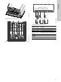
Fig. 14 Wiring diagram, MCB 114
TM03 9447 4007TM05 9329 3713
TM04 3273 3908
Terminal Type Function
1 (VDO) +24 V out Supply to sensor
2 (I IN) AI 3 Sensor 2, 0/4-20 mA
3 (GND) GND Common frame for analog input
4 (TEMP)
5 (WIRE)
AI 4 Temperature sensor 1, Pt100/Pt1000
6 (GND) GND Common frame for temperature sensor 1
7 (TEMP)
8 (WIRE)
AI 5 Temperature sensor 2, Pt100/Pt1000
9 (GND) GND Common frame for temperature sensor 2
1 98765432
1
2
1
1
1
0
VDO
I IN
GND
TEMP
WIRE
GND
TEMP
WIRE
GND
+
-
+

Appendix
14
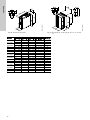
1)
The dimensions are maximum height, width and depth.
TM03 9000 2807
TM03 9002 2807
Fig. 15 Enclosures A2 and A3 Fig. 16 Enclosures A4, A5, B1, B2, B3, B4, C1, C2, C3 and
C4
B4, C3, C4
Enclosure
Height [mm]
1)
Width [mm]
1)
Depth [mm]
1)
Screw holes [mm]
Weight [kg]
AaBbC
C
)
cØdØef
A2 268 257 90 70 205 219 8 11 5.5 9 4.9
IP21/NEMA1 375 350 90 70 205 219 8 11 5.5 9 5.3
A3 268 257 130 110 205 219 8 11 5.5 9 6.6
IP21/NEMA1 375 350 130 110 205 219 8 11 5.5 9 7
A4 420 401 200 171 175 175 8.2 12 6.5 6 9.2
A5 420 402 242 215 200 200 8.2 12 6.5 9 14
B1 480 454 242 210 260 260 12 19 9 9 23
B2 650 624 242 210 260 260 12 19 9 9 27
B3 399 380 165 140 248 262 8 12 6.8 7.9 12
IP21/NEMA1 475 - 165 - 249 262 8 12 6.8 7.9 -
B4 520 495 231 200 242 242 - - 8.5 15 23.5
IP21/NEMA1 670 - 255 - 246 246 - - 8.5 15 -
C1 680 648 308 272 310 310 12 19 9 9.8 45
C2 770 739 370 334 335 335 12 19 9 9.8 65
C3 550 521 308 270 333 333 - - 8.5 17 35
IP21/NEMA1 755 - 329 - 337 337 - - 8.5 17 -
C4 660 631 370 330 333 333 - - 8.5 17 50
IP21/NEMA1 950 - 391 - 337 337 - - 8.5 17 -

Appendix
15
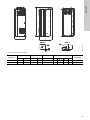
TM05 9331 3713
Fig. 17 Enclosures D1h and D2h
Enclosure
Height [mm]
1)
Width [mm]
1)
Depth [mm]
1)
Screw holes [mm]
Weight [kg]
Aa Bb C c∅d ∅ef
D1h 901 844 325 180 378 20 11 11 25 62
D2h 1107 1051 420 280 378 20 11 11 25 125

Appendix
16
Appendix 1
1. 中国 RoHS
ӗ૱ѝᴹᇣ⢙䍘Ⲵ〠৺ਜ਼䟿
䜘Ԧ〠
ᴹᇣ⢙䍘
䫵
(Pb)
⊎
(Hg)
䭹
(Cd)
ޝԧ䬜
(Cr6+)
ཊⓤ㚄㤟
(PBB)
ཊⓤ㚄㤟䟊
(PBDE)
ঠࡧ⭥䐟ᶯ
X
O
O
O
O
O
㍗പԦ
X
O
O
O
O
O
ᵜ㺘Ṭᦞ SJ/T 11364 Ⲵ㿴ᇊ㕆ࡦ
O
˖㺘⽪䈕ᴹᇣ⢙䍘൘䈕䜘Ԧᡰᴹ൷䍘ᶀᯉѝⲴਜ਼䟿൷൘ GB/T 26572 㿴ᇊⲴ䲀䟿㾱≲ԕлDŽ
X
˖ 㺘⽪䈕ᴹᇣ⢙䍘㠣ቁ൘䈕䜘ԦⲴḀа൷䍘ᶀᯉѝⲴਜ਼䟿䎵ࠪ GB/T 26572 䈕㿴ᇊⲴ䲀䟿㾱≲DŽ
䈕ӗ૱⧟؍֯⭘ᵏ䲀Ѫ 10 ᒤˈḷ䇶ྲᐖമᡰ⽪DŽ
↔⧟؍ᵏ䲀ਚ䘲⭘Ҿӗ૱൘ᆹ㻵о֯⭘䈤᰾Җѝᡰ㿴ᇊⲴᶑԦлᐕ
ӗ૱ѝᴹᇣ⢙䍘Ⲵ〠৺ਜ਼䟿

Declaration of conformity
17
Declaration of conformity 2
GB: EU declaration of conformity
We, Grundfos, declare under our sole responsibility that the product
CUE, to which the declaration below relates, is in conformity with the
Council Directives listed below on the approximation of the laws of the
EU member states.
BG:
, Grundfos, ,
CUE, ,
- .
CZ: Prohlášení o shod EU
My firma Grundfos prohlašujeme na svou plnou odpovdnost, že výrobek
CUE, na který se toto prohlášení vztahuje, je v souladu s níže uvedenými
ustanoveními smrnice Rady pro sblížení právních pedpis lenských
stát Evropského spoleenství.
DE: EU-Konformitätserklärung
Wir, Grundfos, erklären in alleiniger Verantwortung, dass das Produkt
CUE, auf das sich diese Erklärung bezieht, mit den folgenden Richtlinien
des Rates zur Angleichung der Rechtsvorschriften der
EU-Mitgliedsstaaten übereinstimmt.
DK: EU-overensstemmelseserklæring
Vi, Grundfos, erklærer under ansvar at produktet CUE som erklæringen
nedenfor omhandler, er i overensstemmelse med Rådets direktiver der er
nævnt nedenfor, om indbyrdes tilnærmelse til EU-medlemsstaternes
lovgivning.
EE: EÜ vastavusdeklaratsioon
Meie, Grundfos, kinnitame ja kanname ainuisikulist vastutust selle eest,
et toode CUE, mille kohta all olev deklaratsioon käib, on kooskõlas
Nõukogu Direktiividega, mis on nimetatud all pool vastavalt vastuvõetud
õigusaktidele ühtlustamise kohta EÜ liikmesriikides.
ES: Declaración de conformidad de la UE
Grundfos declara, bajo su exclusiva responsabilidad, que el producto
CUE al que hace referencia la siguiente declaración cumple lo
establecido por las siguientes Directivas del Consejo sobre la
aproximación de las legislaciones de los Estados miembros de la UE.
FI: EU-vaatimustenmukaisuusvakuutus
Grundfos vakuuttaa omalla vastuullaan, että tuote CUE, jota tämä
vakuutus koskee, on EU:n jäsenvaltioiden lainsäädännön lähentämiseen
tähtäävien Euroopan neuvoston direktiivien vaatimusten mukainen
seuraavasti.
FR: Déclaration de conformité UE
Nous, Grundfos, déclarons sous notre seule responsabilité, que le
produit CUE, auquel se réfère cette déclaration, est conforme aux
Directives du Conseil concernant le rapprochement des législations des
États membres CE/UE relatives aux normes énoncées ci-dessous.
GR:
, Grundfos,
, ,
.
HU: EU megfelelségi nyilatkozat
Mi, a Grundfos vállalat, teljes felelsséggel kijelentjük, hogy a(z) CUE
termék, amelyre az alábbi nyilatkozat vonatkozik, megfelel az Európai
Unió tagállamainak jogi irányelveit összehangoló tanács alábbi
elírásainak.
IT: Dichiarazione di conformità UE
Grundfos dichiara sotto la sua esclusiva responsabilità che il prodotto
CUE, al quale si riferisce questa dichiarazione, è conforme alle seguenti
direttive del Consiglio riguardanti il riavvicinamento delle legislazioni
degli Stati membri UE.
LT: ES atitikties deklaracija
Mes, Grundfos, su visa atsakomybe pareiškiame, kad produktas CUE,
kuriam skirta ši deklaracija, atitinka žemiau nurodytas Tarybos Direktyvas
dl ES šali nari statym suderinimo.
LV: ES atbilstbas deklarcija
Sabiedrba Grundfos ar pilnu atbildbu pazio, ka produkts CUE, uz kuru
attiecas tlk redzam deklarcija, atbilst tlk nordtajm Padomes
direktvm par EK/ES dalbvalstu normatvo aktu tuvinšanu.
NL: EU-conformiteitsverklaring
Wij, Grundfos, verklaren geheel onder eigen verantwoordelijkheid dat
product CUE, waarop de onderstaande verklaring betrekking heeft, in
overeenstemming is met de onderstaande Richtlijnen van de Raad
inzake de onderlinge aanpassing van de wetgeving van de EU-lidstaten.
PL: Deklaracja zgodnoci UE
My, Grundfos, owiadczamy z pen odpowiedzialnoci, e nasz
produkt CUE, którego deklaracja niniejsza dotyczy, jest zgodny
z nastpujcymi dyrektywami Rady w sprawie zblienia przepisów
prawnych pastw czonkowskich.
PT: Declaração de conformidade UE
A Grundfos declara sob sua única responsabilidade que o produto CUE,
ao qual diz respeito a declaração abaixo, está em conformidade com as
Directivas do Conselho sobre a aproximação das legislações dos
Estados Membros da UE.
RO: Declaraia de conformitate UE
Noi Grundfos declarm pe propria rspundere c produsul CUE, la care
se refer aceast declaraie, este în conformitate cu Directivele de
Consiliu specificate mai jos privind armonizarea legilor statelor membre
UE.
RS: Deklaracija o usklaenosti EU
Mi, kompanija Grundfos, izjavljujemo pod punom vlastitom odgovornošu
da je proizvod CUE, na koji se odnosi deklaracija ispod, u skladu sa dole
prikazanim direktivama Saveta za usklaivanje zakona država lanica
EU.
RU:
, Grundfos, ,
CUE, ,
- .
SE: EU-försäkran om överensstämmelse
Vi, Grundfos, försäkrar under ansvar att produkten CUE, som omfattas
av nedanstående försäkran, är i överensstämmelse med de rådsdirektiv
om inbördes närmande till EU-medlemsstaternas lagstiftning som listas
nedan.
CN: 欧盟符合性声明
我们,格兰富,在我们的全权责任下声明,产品 CUE 系列,其制造和性能
完全符合以下所列欧盟委员会指令。
KO: EU 적합성 선언
Grundfos 는 아래의 선언과 관련된 CUE 제품이 EU 회원국 법률에 기반하
여 아래의 이사회 지침을 준수함을 단독 책임 하에 선언합니다 .
AR: (EU)
CUE
(EU).

Declaration of conformity
18
— Low Voltage Directive (2014/35/EU).
Standards used:
EN 61800-5-1:2007.
— EMC Directive (2014/30/EU).
Standards used:
EN 61800-3: 2004/A1: 2012.
This EU declaration of conformity is only valid when published as part of
the Grundfos safety instructions (publication number 96706951).
Bjerringbro, 8th April 2015
Svend Aage Kaae
Director
Grundfos Holding A/S
Poul Due Jensens Vej 7
8850 Bjerringbro, Denmark
Person authorised to compile technical file and
empowered to sign the EC declaration of conformity.

Declaration of conformity
19
Declaration of conformity 3
RUS
CUE
Ɋɭɤɨɜɨɞɫɬɜɨɩɨɷɤɫɩɥɭɚɬɚɰɢɢ
Ɋɭɤɨɜɨɞɫɬɜɨɩɨɷɤɫɩɥɭɚɬɚɰɢɢɧɚɞɚɧɧɨɟɢɡɞɟɥɢɟɹɜɥɹɟɬɫɹɫɨɫɬɚɜɧɵɦɢɜɤɥɸɱɚɟɬɜɫɟɛɹɧɟɫɤɨɥɶɤɨ
ɱɚɫɬɟɣ
ɑɚɫɬɶɧɚɫɬɨɹɳɟɟ©Ɋɭɤɨɜɨɞɫɬɜɨɩɨɷɤɫɩɥɭɚɬɚɰɢɢª
ɑɚɫɬɶɷɥɟɤɬɪɨɧɧɚɹɱɚɫɬɶ©ɉɚɫɩɨɪɬɊɭɤɨɜɨɞɫɬɜɨɩɨɦɨɧɬɚɠɭɢɷɤɫɩɥɭɚɬɚɰɢɢªɪɚɡɦɟɳɟɧɧɚɹɧɚ
ɫɚɣɬɟɤɨɦɩɚɧɢɢȽɪɭɧɞɮɨɫɉɟɪɟɣɞɢɬɟɩɨɫɫɵɥɤɟɭɤɚɡɚɧɧɨɣɜɤɨɧɰɟɞɨɤɭɦɟɧɬɚ
ɑɚɫɬɶɢɧɮɨɪɦɚɰɢɹɨɫɪɨɤɟɢɡɝɨɬɨɜɥɟɧɢɹɪɚɡɦɟɳɟɧɧɚɹɧɚɮɢɪɦɟɧɧɨɣɬɚɛɥɢɱɤɟɢɡɞɟɥɢɹ
ɋɜɟɞɟɧɢɹɨɩɨɞɬɜɟɪɠɞɟɧɢɢɫɨɨɬɜɟɬɫɬɜɢɹ
ɉɪɟɨɛɪɚɡɨɜɚɬɟɥɢɱɚɫɬɨɬɵ&8(ɩɨɞɬɜɟɪɠɞɟɧɢɟɫɨɨɬɜɟɬɫɬɜɢɹɬɪɟɛɨɜɚɧɢɹɦɌɟɯɧɢɱɟɫɤɢɯɪɟɝɥɚɦɟɧɬɨɜ
ɌɚɦɨɠɟɧɧɨɝɨɫɨɸɡɚɌɊɌɋ©ɈɛɟɡɨɩɚɫɧɨɫɬɢɧɢɡɤɨɜɨɥɶɬɧɨɝɨɨɛɨɪɭɞɨɜɚɧɢɹªɌɊɌɋ
©ɗɥɟɤɬɪɨɦɚɝɧɢɬɧɚɹɫɨɜɦɟɫɬɢɦɨɫɬɶɬɟɯɧɢɱɟɫɤɢɯɫɪɟɞɫɬɜª
KAZ
CUE
ɉɚɣɞɚɥɚɧɭɛɨɣɵɧɲɚɧԝɫԕɚɭɥɵԕ
Ⱥɬɚɭɥɵԧɧɿɦɝɟɚɪɧɚɥԑɚɧɩɚɣɞɚɥɚɧɭɛɨɣɵɧɲɚɧԝɫԕɚɭɥɵԕԕԝɪɚɦɚɥɵɛɨɥɵɩɤɟɥɟɞɿɠԥɧɟɤɟɥɟɫɿ
ɛԧɥɿɦɞɟɪɞɟɧɬԝɪɚɞɵ
ɛԧɥɿɦɚɬɚɭɥɵ©ɉɚɣɞɚɥɚɧɭɛɨɣɵɧɲɚɧԝɫԕɚɭɥɵԕª
ɛԧɥɿɦȽɪɭɧɞɮɨɫɤɨɦɩɚɧɢɹɫɵɧɵԙɫɚɣɬɵɧɞɚɨɪɧɚɥɚɫԕɚɧɷɥɟɤɬɪɨɧɞɵɛԧɥɿɦ©ɌԧɥԕԝɠɚɬԔԝɪɚɫɬɵɪɭ
ɠԥɧɟɩɚɣɞɚɥɚɧɭɛɨɣɵɧɲɚɧԝɫԕɚɭɥɵԕªԔԝɠɚɬɫɨԙɵɧɞɚɤԧɪɫɟɬɿɥɝɟɧɫɿɥɬɟɦɟɚɪԕɵɥɵԧɬɿԙɿɡ
ɛԧɥɿɦԧɧɿɦɧɿԙɮɢɪɦɚɥɵԕɬɚԕɬɚɲɚɫɵɧɞɚɨɪɧɚɥɚɫԕɚɧɲɵԑɚɪɵɥԑɚɧɭɚԕɵɬɵɠԧɧɿɧɞɟɝɿɦԥɥɿɦɟɬ
ɋԥɣɤɟɫɬɿɤɦԥɥɿɦɞɟɦɟɫɿɬɭɪɚɥɵɚԕɩɚɪɚɬ
&8(ɠɢɿɥɿɤɬԛɪɥɟɧɞɿɪɝɿɲɬɟɪɿɚɪɧɚɥԑɚɧɬɢɩɬɿɤɠԛɣɟɥɟɪɞɿԙɬɢɩɬɟɪɿɛɨɣɵɧɲɚɠԛɣɟɛɨɣɵɧɲɚ
ɬɟɯɧɢɤɚɥɵԕɬɚɥɚɩɬɚɪԑɚɫԥɣɤɟɫɬɿɝɿɧɪɚɫɬɚɞɵɌɊɌɋ©ɇɢɡɤɨɜɨɥɶɬɧɨɟɨɛɨɪɭɞɨɜɚɧɢɹ
ɛɟɡɨɩɚɫɧɨɫɬɢªɌɊɌɋ©ɆɚɲɢɧɚɥɚɪɦɟɧɠɚɛɞɵԕɬɚɪɞɵԙԕɚɭɿɩɫɿɡɞɿɝɿɬɭɪɚɥɵªɌɊɌɋ
©Ɍɟɯɧɢɤɚɥɵԕԕԝɪɚɥɞɚɪɞɵԙɷɥɟɤɬɪɨɦɚɝɧɢɬɬɿɤɬԥɭɟɥɞɿɥɿɝɿª
KG
CUE
ɉɚɣɞɚɥɚɧɭɭɛɨɸɧɱɚɤɨɥɞɨɧɦɨ
Ⱥɬɚɥɝɚɧɠɚɛɞɭɭɧɭɩɚɣɞɚɥɚɧɭɭɛɨɸɧɱɚɤɨɥɞɨɧɦɨɤɭɪɚɦɞɵɤɠɚɧɚԧɡԛɧԧɛɢɪɧɟɱɟɛԧɥԛɤɱԧɧԛɤɚɦɬɵɣɬ
Ȼԧɥԛɤ©ɉɚɣɞɚɥɚɧɭɭɛɨɸɧɱɚɤɨɥɞɨɧɦɨª
Ȼԧɥԛɤ©ɉɚɫɩɨɪɬɉɚɣɞɚɥɚɧɭɭɠɚɧɚɦɨɧɬɚɠɛɨɸɧɱɚɤɨɥɞɨɧɦɨªɷɥɟɤɬɪɨɧɞɭɤɛԧɥԛɝԛȽɪɭɧɞɮɨɫ
ɤɨɦɩɚɧɢɹɧɵɧɫɚɣɬɵɧɞɚɠɚɣɝɚɲɤɚɧȾɨɤɭɦɟɧɬɬɢɧɚɹɝɵɧɞɚɤԧɪɫԧɬԛɥɝԧɧɲɢɥɬɟɦɟɝɟɤɚɣɪɵɥɵԙɵɡ
Ȼԧɥԛɤɠɚɛɞɭɭɧɭɧɮɢɪɦɚɥɵɤɬɚɤɬɚɫɵɧɞɚɠɚɣɝɚɲɤɚɧɞɚɹɪɞɨɨɦԧԧɧԧɬԛɬɭɭɪɚɥɭɭɦɚɚɥɵɦɚɬ
ɒɚɣɤɟɲɬɢɤɬɢɛɚɚɥɨɨɛɨɸɧɱɚɦɚɚɥɵɦɚɬɚɥɭɭԛɱԛɧ
ɕɲɬɵɤԧɡɝԧɪɬԛԛɱԛɥԧɪ&8(Ȼɚɠɵɛɢɪɢɦɞɢɝɢɧɢɧɬɟɯɧɢɤɚɥɵɤɪɟɝɥɚɦɟɧɬɬɟɪɞɢɧɬɚɥɚɩɬɚɪɵɧɵɧ
ɫɚɤɬɚɥɵɲɵɧɚɬɚɫɬɵɤɬɨɨɫɭɧɚɧԧɬɤԧɧ7ɊɌɋɧɚɱɚɪɞɵɝɵɠɚɛɞɭɭɥɚɪɞɵɧɤɨɨɩɫɭɡɞɭɝɭ
ɠԧɧԛɧɞԧ7ɊɌɋɦɚɲɢɧɚɥɚɪɞɵɧɠɚɧɚɠɚɛɞɭɭɥɚɪɞɵɧɤɨɨɩɫɭɡɞɭɝɭɠԧɧԛɧɞԧ7ɊɌɋ
ɬɟɯɧɢɤɚɥɵɤɤɚɪɚɠɚɬɬɚɪɞɵɧɷɥɟɤɬɪɨɦɚɝɧɢɬɬɢɤɤɟɥԛԛɱԛɥԛɤ

Declaration of conformity
20
ARM
CUE
ಈಗಈಊಟಧಕಛಈಝಘಌಣಝಈಧಖ
ɨʕʌɸʃ ʔɸʗʛɸʕʏʗʋɸʍ ʎɸʇɸɺʏʗʅʋɸʍ ʈɼʓʍɸʗʆɿ ɹɸʉʆɸʘɸʅ ɾ ʋʂ ʛɸʍʂ ʋɸʔɼʗʂʘ.
ɝɸʔ 1. ʔʏʙʌʍ «ɠɸʇɸɺʏʗʅʋɸʍ ʈɼʓʍɸʗʆ»:
ɝɸʔ 2. ɾʃɼʆʖʗʏʍɸʌʂʍ ʋɸʔ. ɸʌʍ ɾɵ «Ɋʍʈʍɸɺʂʗ: ɝʏʍʖɸʁʋɸʍ ʞ
ʎɸʇɸɺʏʗʅʋɸʍ ʈɼʓʍɸʗʆ» ʖɼʉɸɻʗʕɸʅ «Ɍʗʏʙʍɻʝʏʔ». Ɋʍʘɼʛʚɸʔʖɸʀʉʀʂʕɼʗʒʏʙʋʍʎʕɸʅʇʉʏʙʋʏʕ.
ɝɸʔ 3. ʖɼʉɼʆʏʙʀʌʏʙʍ ɸʗʖɸɻʗʋɸʍ ɸʋʔɸʀʕʂ ʕɼʗɸɹɼʗʌɸʃɵ ʍʎʕɸʅ ʔɸʗʛɸʕʏʗʋɸʍ ʑʂʖɸʆʂ ʕʗɸ:
əɸʋɸʑɸʖɸʔʄɸʍʏʙʀʌɸʍ ʋɸʔʂʍ ʇɸʌʖɸʗɸʗʏʙʀʌɸʍ ʖɼʉɼʆʏʙʀʌʏʙʍʍɼʗɵ
CUE ʇɸʊɸʄɸʆɸʍʏʙʀʌɸʍ ʆʏʍʕɼʗʖɼʗ ʇɸʕɸʔʖɸɺʗʕɸʅ ɼʍ ཆའོྃའུཪཱཱིུཪཷཱྀཨུའཱུཾཤཬཱུཪའའཱུ
འཱུཷཱུའའཿརཪཹའའཱཱེུུཤཿཪཱུའཱིའཹའཾའོཬའཱུC7ɊɌɋ©ནའཿཫའཿཱིའཱོུའཿྃའཽཷཿཷཱཱཱྀིུཤཿཪ
འཱཽུཾའཱུརཷཱྀཨུའཱཱིུའོཪཱུª7ɊɌɋ©ཆཤྃཤཱུའཱུཤཿཪཤཱྀོའཿྃའཽཷཿཷཱཱཱྀིུཤཿཪའཱཽུཾའཱུརཷཱྀཨུའཱཱིུའོཪཱུª
7ɊɌɋ©དཤཬཱུཪའའཱོུའཿྃའཽཷཿཷཱཱཱྀིུཤཿཪསཫཤཾཿའཱིའརཱུཪོའའཱུའཱིའཾཤཱཤཫཪཷཱྀཨུཷཱཱྀུª
&8(±ɤȼɬ
&8(ɤȼɬ
http://net.grundfos.com/qr/i/99035178
http://net.grundfos.com/qr/i/99449240
10000236994 0819
ECM:1267075
Pagina se încarcă...
Pagina se încarcă...
-
 1
1
-
 2
2
-
 3
3
-
 4
4
-
 5
5
-
 6
6
-
 7
7
-
 8
8
-
 9
9
-
 10
10
-
 11
11
-
 12
12
-
 13
13
-
 14
14
-
 15
15
-
 16
16
-
 17
17
-
 18
18
-
 19
19
-
 20
20
-
 21
21
-
 22
22


Grundfos CUE Safety Instructions And Other Important Information
- Tip
- Safety Instructions And Other Important Information
în alte limbi
- English: Grundfos CUE
Lucrări înrudite
-
Grundfos A Safety Instructions And Other Important Information
-
-
-
-
-
Grundfos UP circulator pump MEDIUM Instrucțiuni de utilizare
-
-
Grundfos MI 202 Manual de utilizare
-
-
Alte documente
-
STEINEL RS PRO R10 basic SC neutralweiß Manual de utilizare
-
STEINEL RS PRO CONNECT R20 Q Sensor Switched LED Indoor Light Manual de utilizare
-
Vinten Quattro SE Pedestal Operator Guide
-
Maico MVS 6 Mounting And Operating Instructions
-
RAIDER Pro RDP-SPC20 Manual de utilizare
-
Boss KATANA-AIR Manualul proprietarului
-
Yamaha PM10 Ghid de instalare
-
-
-
LG LAS453B Manual de utilizare