
CR, CRI, CRN, CRT
ATEX-approved pumps
Installation and operating instructions
GRUNDFOS INSTRUCTIONS

2

3
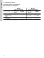
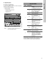
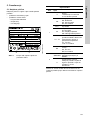
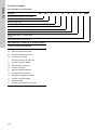
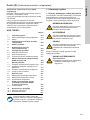
Table of contents
CR, CRI, CRN, CRT
ATEX-approved pumps
English (GB)
Installation and operating instructions. . . . . . . . . . . . . . . . . . . . . . . . . . . . . . . . . 5
Български (BG)
Упътване за монтаж и експлоатация. . . . . . . . . . . . . . . . . . . . . . . . . . . . . . . 18
Čeština (CZ)
Montážní a provozní návod. . . . . . . . . . . . . . . . . . . . . . . . . . . . . . . . . . . . . . . . 31
Deutsch (DE)
Montage- und Betriebsanleitung . . . . . . . . . . . . . . . . . . . . . . . . . . . . . . . . . . . . 44
Dansk (DK)
Monterings- og driftsinstruktion. . . . . . . . . . . . . . . . . . . . . . . . . . . . . . . . . . . . . 57
Eesti (EE)
Paigaldus- ja kasutusjuhend. . . . . . . . . . . . . . . . . . . . . . . . . . . . . . . . . . . . . . . 70
Español (ES)
Instrucciones de instalación y funcionamiento . . . . . . . . . . . . . . . . . . . . . . . . . 83
Suomi (FI)
Asennus- ja käyttöohjeet. . . . . . . . . . . . . . . . . . . . . . . . . . . . . . . . . . . . . . . . . . 96
Français (FR)
Notice d'installation et de fonctionnement. . . . . . . . . . . . . . . . . . . . . . . . . . . . 109
Ελληνικά (GR)
Οδηγίες εγκατάστασης και λειτουργίας . . . . . . . . . . . . . . . . . . . . . . . . . . . . . . 122
Hrvatski (HR)
Montažne i pogonske upute . . . . . . . . . . . . . . . . . . . . . . . . . . . . . . . . . . . . . . 135
Magyar (HU)
Telepítési és üzemeltetési utasítás. . . . . . . . . . . . . . . . . . . . . . . . . . . . . . . . . 148
Italiano (IT)
Istruzioni di installazione e funzionamento . . . . . . . . . . . . . . . . . . . . . . . . . . . 161
Lietuviškai (LT)
Įrengimo ir naudojimo instrukcija . . . . . . . . . . . . . . . . . . . . . . . . . . . . . . . . . . 174
Latviešu (LV)
Uzstādīšanas un ekspluatācijas instrukcija. . . . . . . . . . . . . . . . . . . . . . . . . . . 187
Nederlands (NL)
Installatie- en bedieningsinstructies . . . . . . . . . . . . . . . . . . . . . . . . . . . . . . . . 200
Polski (PL)
Instrukcja montażu i eksploatacji . . . . . . . . . . . . . . . . . . . . . . . . . . . . . . . . . . 213
Português (PT)
Instruções de instalação e funcionamento . . . . . . . . . . . . . . . . . . . . . . . . . . . 226

Table of contents
4
CR, CRI, CRN, CRT
ATEX-approved pumps
Română (RO)
Instrucţiuni de instalare şi utilizare . . . . . . . . . . . . . . . . . . . . . . . . . . . . . . . . . 239
Srpski (RS)
Uputstvo za instalaciju i rad . . . . . . . . . . . . . . . . . . . . . . . . . . . . . . . . . . . . . . 252
Русский (RU)
Руководство по монтажу и эксплуатации . . . . . . . . . . . . . . . . . . . . . . . . . . 265
Svenska (SE)
Monterings- och driftsinstruktion . . . . . . . . . . . . . . . . . . . . . . . . . . . . . . . . . . . 279
Slovensko (SI)
Navodila za montažo in obratovanje. . . . . . . . . . . . . . . . . . . . . . . . . . . . . . . . 292
Slovenčina (SK)
Návod na montáž a prevádzku . . . . . . . . . . . . . . . . . . . . . . . . . . . . . . . . . . . . 305
Türkçe (TR)
Montaj ve kullanım kılavuzu . . . . . . . . . . . . . . . . . . . . . . . . . . . . . . . . . . . . . . 318
Українська (UA)
Інструкції з монтажу та експлуатації . . . . . . . . . . . . . . . . . . . . . . . . . . . . . . 331
中文 (CN)
安装和使用说明书 . . . . . . . . . . . . . . . . . . . . . . . . . . . . . . . . . . . . . . . . . . . . . . 345
Norsk (NO)
Installasjons- og driftsinstruksjoner. . . . . . . . . . . . . . . . . . . . . . . . . . . . . . . . . 356
ﺔﻳﺑﺭﻌﻟﺍ (AR)
ﻝﻳﻐﺷﺗﻟﺍ ﻭ ﺏﻳﻛﺭﺗﻟﺍ ﺕﺎﻣﻳﻠﻌﺗ . . . . . . . . . . . . . . . . . . . . . . . . . . . . . . . . . . . . . 381

English (GB)
5
English (GB) Installation and operating instructions
Original installation and operating instructions
These supplementary installation and operating
instructions apply to the ATEX-approved Grundfos
CR pumps.
The CR pumps comply with ATEX Directive 2014/34/
EU.
The pumps are suitable for use in zones classified
according to Directive 1999/92/EC. In case of doubt,
consult the above-mentioned directives, or contact
Grundfos.
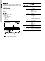
CONTENTS
Page
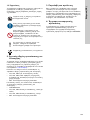
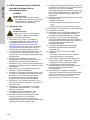
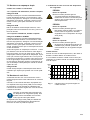
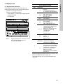
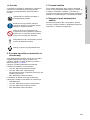
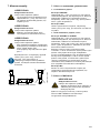
1. General information
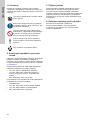
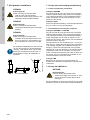
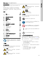
1.1 Hazard statements
The symbols and hazard statements below may
appear in Grundfos installation and operating
instructions, safety instructions and service
instructions.
The hazard statements are structured in the
following way:
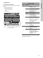
1. General information
5
1.1 Hazard statements
5
1.2 Notes
6
2. Related installation and operating
instructions
6
3. Receiving the product
6
4. Explosion protection document
6
5. Identification
7
5.1 Nameplate
7
5.2 Type key
8
5.3 Drive-end motor bearing
9
6. Scope of ATEX categories for CR
pumps
10
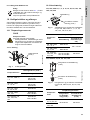
7. Installing the product
11
7.1 Pump with single seal
11
7.2 Pump with MAGdrive
11
7.3 Pump with double seal
12
7.4 Bare-shaft pumps
12
8. Operating conditions
13
8.1 Maximum ambient temperature
13
8.2 Maximum liquid temperature
13
8.3 Temperature calculation
14
9. Before starting up and during operation
of an ATEX-approved pump
15
9.1 Checklist
15
10. Maintenance and inspection
17
10.1 Tightening torques
17
10.2 Shaft seal
17
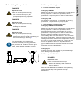
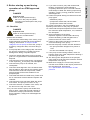
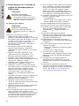
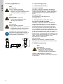
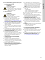
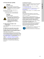
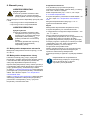
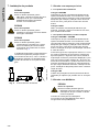
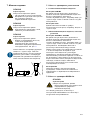
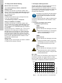
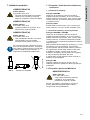
Read this document before installing the
product. Installation and operation must
comply with local regulations and accepted
codes of good practice.
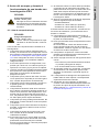
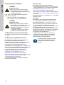
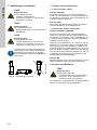
DANGER
Indicates a hazardous situation which, if
not avoided, will result in death or serious
personal injury.
WARNING
Indicates a hazardous situation which, if
not avoided, could result in death or
serious personal injury.
CAUTION
Indicates a hazardous situation which, if
not avoided, could result in minor or
moderate personal injury.
SIGNAL WORD
Description of hazard
Consequence of ignoring the warning.
- Action to avoid the hazard.

English (GB)
6
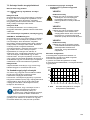
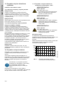
1.2 Notes
The symbols and notes below may appear in
Grundfos installation and operating instructions,
safety instructions and service instructions.
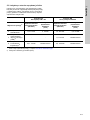
2. Related installation and operating
instructions
The X on the nameplate indicates that the pump is
subject to special conditions for safe use as
described in these instructions. The nameplate
markings are described in the table in section
5. Identification.
In addition to these instructions, observe the
following installation and operating instructions:
• CR, CRI, CRN: for standard pumps
• CR, CRI, CRN, CRT: removal of transport bracket
and fitting of motor. For pumps without motor
• MG: Grundfos standard motors.
For special versions of the CR pumps, observe the
relevant installation and operating instructions:
•CRN MAGdrive
• CR, CRI, CRN: double seal, back-to-back
• CR, CRI, CRN: double seal, tandem
• MG: Grundfos standard motors.
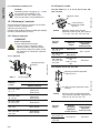
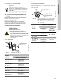
3. Receiving the product
If the pump is delivered without a motor, mount the
motor and then adjust the chamber stack and shaft
seal according to the procedure described in the
installation and operating instructions, "Removal of
transport bracket and fitting of motor", supplied with
the pump.
4. Explosion protection document
The combination of CR pump and all monitoring
equipment must be described in the explosion
protection document according to Directive 1999/92/
EC.
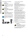
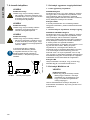
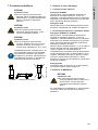
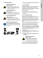
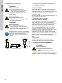
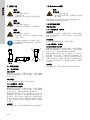
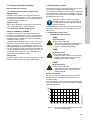
Observe these instructions for explosion-
proof products.
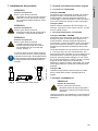
A blue or grey circle with a white graphical
symbol indicates that an action must be
taken.
A red or grey circle with a diagonal bar,
possibly with a black graphical symbol,
indicates that an action must not be taken
or must be stopped.
If these instructions are not observed, it
may result in malfunction or damage to the
equipment.
Tips and advice that make the work easier.

English (GB)
7
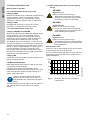
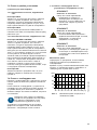
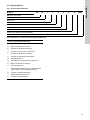
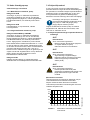
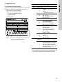
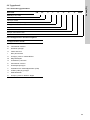
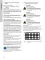
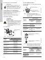
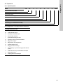
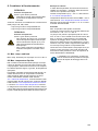
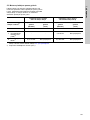
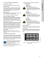
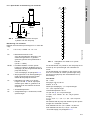
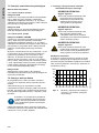
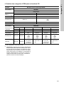
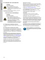
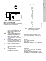
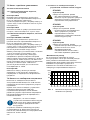
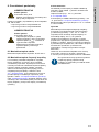
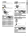
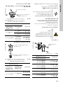
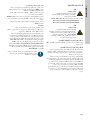
5. Identification
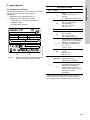
5.1 Nameplate
The nameplate on the pump head gives the following
details:
• data of standard pump
• data of ATEX marking
– technical file number
– serial number
– Ex category.
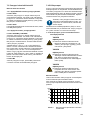
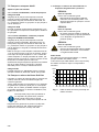
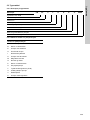
Fig. 1 Example of a CR nameplate with ATEX
approval
Data for the ATEX marking only refers to the part
including the coupling. The motor has a separate
nameplate.
TM07 5039 0719
DK-8850 Bjerringbro,Denmark
Model-PN-SN
Type
Hz
pmax/tmax
Tech file no
Made in Denmark
P code: P115482
bar/°C
min
-1
excl.motor 500kg
/hm
3
kW [P2]
H/H max m 0(,
ȘS
B-96123526-98438832
CR255-1-1A-F-A-E-HQQE
435/248
2917
64
CCW
98964685X
99356347
50/60
4.0
0.7 69.7
14.2/22.1
21
435-580/176
II 3G Ex h IIC T4...T3 Gb
ATEX rating
Pos. Description
1
II
Group
I: Underground in mines
II: Surface equipment
3G
Category
M2: Mining
2G, 3G: Gas/vapours
2D, 3D: Dust
Ex h Protection type
IIC
Environment group
IIC: Gas/vapours
IIIC: Combustible dust
IIIB: Non-magnetic dust
T4...T3
Maximum surface
temperature according to
80079-36.
Temperature range or
specific temperature.
T4...T3: Gas
T125 °C: Dust
Gb
EPL (Equipment Protection
Level).
Gb, Gc: Gas
Db, Dc: Dust
2
98964685
File number for technical file
stored at DEKRA.
X
Indicates that the equipment
is subject to special
conditions for safe use. The
conditions are mentioned in
this document.

English (GB)
8
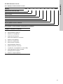
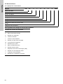
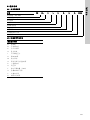
5.2 Type key
5.2.1 Type key example
5.2.2 Key to codes for pump version
Example CR 32- 2 1- X- X- X- X- XXXX
Type range: CR, CRN
Rated flow rate in m
3
/h
Number of stages
Number of impellers with reduced diameter
Code for pump version
Code for pipe connection
Code for materials
Code for rubber pump parts
Code for shaft seal
Codes for pump version
A Basic version
BOversize motor
E Pump with certificate
H Horizontal version
I Different pressure rating
K Pump with low NPSH
M Magnetic drive
O Cleaned and dried
P Undersize motor
S High-pressure pump
T Thrust handling device (THD)
U ATEX approved pump
Y Electropolished
Z Pumps with bearing flange

English (GB)
9
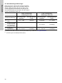
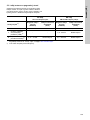
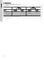
5.3 Drive-end motor bearing
Make sure to use the correct type of drive-end (DE)
motor bearing for the bare-shaft pump. Please check
the specific pump range and pump version stated on
the nameplate and select the corresponding DE
bearing.
1)
Refer to the codes for pump version in section 5.2 Type key.
2)
Factory product variants (FPV).
DE bearing
CR 1-64 pump range
DE bearing
CR 95-255 pump range
Pump version
1)
Deep-groove ball
bearing
(62/63xx)
Angular contact
bearing
(73xx)
Deep-groove ball
bearing
(62/63xx)
Angular contact
bearing
(73xx)
A Standard pump 0.37 - 3 kW 4-45 kW 75-200 kW 5.5 - 55 kW
T
Pump with thrust
handling device
(THD)
2)
- - 5.5 - 55 kW Not allowed
Z
Pump with bearing
flange
2)
0.37 - 45 kW Not allowed 5.5 - 200 kW Not allowed

English (GB)
10
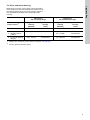
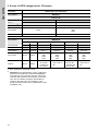
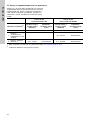
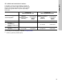
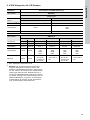
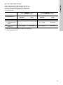
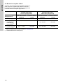
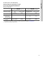
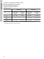
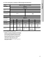
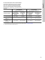
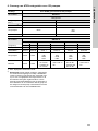
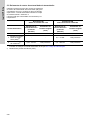
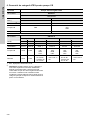
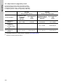
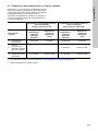
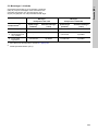
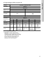
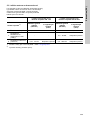
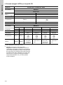
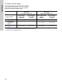
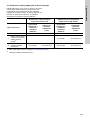
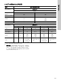
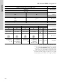
6. Scope of ATEX categories for CR pumps
1)
EPL: Equipment Protection Level.
2)
Important: The link between groups, categories
and zones is explained in Directive1999/92/EC.
Note that this is a minimum directive. Some EU
countries may therefore have stricter local rules.
The user or installer is always responsible for
checking that the group and category of the
pump correspond to the zone classification of the
installation site.
Directive ATEX-approved CR pumps
2014/34/EU GROUP I
Category M
Environment:
1 2
EPL
1)
: Ma Mb
1999/92/EC
2)
--
CR pumps None
CR
CRI
CRN
Motors None None
2014/34/EU GROUP II
Category 1 Category 2 Category 3
Environment:
G D G D G D
EPL
1)
: Ga Da Gb Db Gc Dc
1999/92/EC
2)
Zone 0 Zone 20 Zone 1 Zone 21 Zone 2 Zone 22
CR pumps None None
CR
CRI
CRN
CRT
CR
CRI
CRN
CRT
CR
CRI
CRN
CRT
CR
CRI
CRN
CRT
Motors None None
• II 2G Ex eb
IIC T3 Gb
• II 2G Ex db
IIC T4 Gb
• II 2D Ex tb
IIIC T125 °C
Db
• II 2G Ex eb
IIC T3 Gb
• II 2G Ex db
IIC T4 Gb
• II 3D Ex tc
IIIC T125 °C
Dc

English (GB)
11
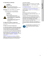
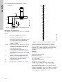
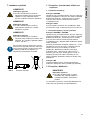
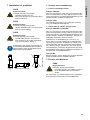
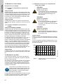
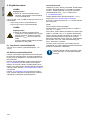
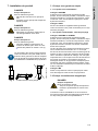
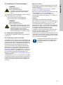
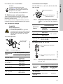
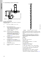
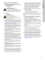
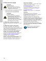
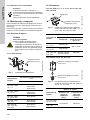
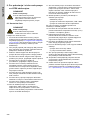
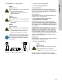
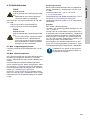
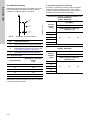
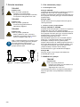
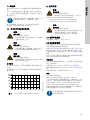
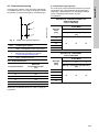
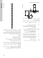
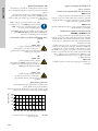
7. Installing the product
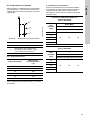
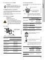
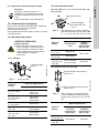
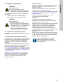
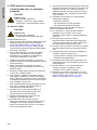
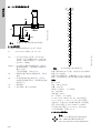
Fig. 2 Positioning the pump
7.1 Pump with single seal
7.1.1 Non-flammable liquids
Category 2G/D/M2
Make sure that the pump is filled with pumped liquid
during operation. If this is not possible, ensure
appropriate monitoring, for example dry-running
protection to stop the pump in case of malfunction.
Category 3G/D
No additional monitoring, for example dry-running
protection, is required for the pump system.
7.1.2 Flammable liquids, pump unit
Category 2G/D/M2 and 3G/D/M2
Make sure that the pump is filled with pumped liquid
during operation. If this is not possible, ensure
appropriate monitoring, for example dry-running
protection to stop the pump in case of malfunction.
Ensure sufficient ventilation around the pump.
The leakage rate of a shaft seal is 1-10 ml for each
24 hours of operation. For some types of liquids, the
leakage will not be visible due to evaporation. During
the run-in period, larger leakage of 1-20 ml per 24
hours of operation can occur. Liquids like oil or
glycol-water mixtures evaporate slower than water
and will leave residuals. Ensure proper ventilation to
maintain the zone classification.
Category M2
Protect the pump with a guard to prevent damage
from falling or ejected objects.
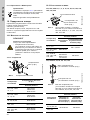
7.2 Pump with MAGdrive
See the CRN MAGdrive installation and operating
instructions at http://net.grundfos.com/qr/i/
96464310.
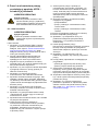
DANGER
Explosion risk
Death or serious personal injury
- Do not let the pump run dry.
- Make sure that the pump is filled with
pumped liquid during operation.
DANGER
Explosion risk
Death or serious personal injury
- Replace the shaft seal if increased
leakage is observed.
DANGER
Explosion risk
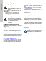
Death or serious personal injury
- Always install the pump with the motor
above the pump to avoid overheating of
the motor bearings. See fig. 2.
The responsibility for checking the
functions of the dry-running protection,
such as flow rate, sealing pressure and
temperature of the barrier or flushing
liquid, rests with the installer or owner.
TM01 1241 4102
DANGER
Explosion risk
Death or serious personal injury
- Always fill the pump with liquid and
ensure that the required minimum flow
rate is obtained.

English (GB)
12
7.3 Pump with double seal
Back-to-back or tandem
7.3.1 Non-flammable liquids, pump unit
Category 2G/D
Make sure that the pump is filled with pumped liquid
during operation. If this is not possible, ensure
appropriate monitoring, for example dry-running
protection to stop the pump in case of malfunction.
Category 3G/D
No additional monitoring, such as dry-running
protection, is required for the pump system.
7.3.2 Flammable liquids, pump unit
Category 2G/D/M2 and 3G/D/M2
Make sure that the pump is filled with pumped liquid
during operation. If this is not possible, ensure
appropriate monitoring, for example dry-running
protection to stop the pump in case of malfunction.
Ensure sufficient ventilation around the pump.
The leakage rate of a shaft seal is 1-10 ml for each
24 hours of operation. For some types of liquids, the
leakage will not be visible due to evaporation. During
the run-in period, larger leakage of 1-20 ml per 24
hours of operation can occur. Liquids like oil or
glycol-water mixtures evaporate slower than water
and will leave residuals. Ensure proper ventilation to
maintain the zone classification.
Category M2
Protect the pump by a guard to prevent damage from
falling or ejected objects.
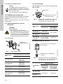
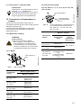
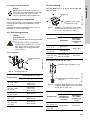
7.4 Bare-shaft pumps
Bare-shaft pumps with motors of 4 kW and up must
use angular contact bearings.
However, if the pumps are fitted with a thrust
handling device (THD) or a bearing flange, they must
never be used with angular contact bearings. If in
doubt, contact Grundfos.
The thrust handling device (THD) is factory-fitted on
CR, CRN 95-255 for motor sizes of 75 kW and
above.
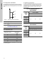
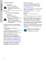
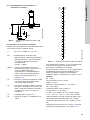
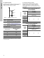
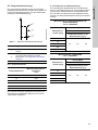
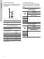
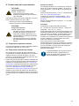
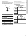
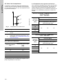
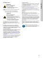
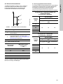
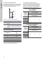
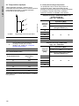
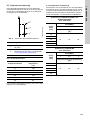
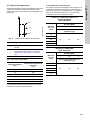
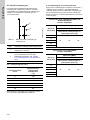
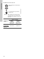
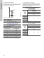
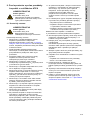
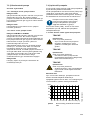
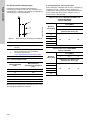
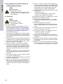
7.4.1 Bare-shaft pumps with a thrust handling
device
Minimum flow rate
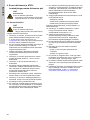
Due to the risk of overheating, do not use the pump
at flows below the minimum flow rate.
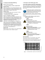
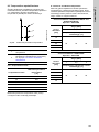
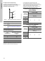
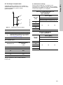
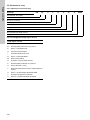
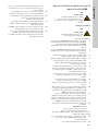
The curve below shows the minimum flow rate as a
percentage of the rated flow rate in relation to the
liquid temperature.
Fig. 3 Minimum flow rate in percentage of
nominal flow
Check if the pump is fitted with a thrust
handling device (THD). If the pump is a
THD marked pump, follow the instructions
below.
DANGER
Explosion risk
Death or serious personal injury
- Temperature monitoring of the motor
bearings is required to ensure that the
pump stops in case of overheating.
DANGER
Explosion risk
Death or serious personal injury
- Do not use ATEX motors with angular
contact bearings on pumps fitted with a
thrust handling device (THD).
DANGER
Explosion risk
Death or serious personal injury
- Temperature sensors must be installed
by qualified persons in accordance with
local regulations.
TM02 8290 4903
40 50 60 70 80 90 100 110 120
t [°C]
0
10
20
30
Qmin
[%]

English (GB)
13
8. Operating conditions
See the CR, CRI, CRN installation and operating
instructions:
– http://net.grundfos.com/qr/i/96462123
– http://net.grundfos.com/qr/i/99078486
8.1 Maximum ambient temperature
The maximum ambient temperature for the pump: -
20 to +60 °C.
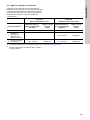
8.2 Maximum liquid temperature
In normal pump operation, the highest temperatures
are to be expected at the surface of the pump casing
and at the shaft seal. The surface temperature will
normally follow the temperature of the liquid.
You can calculate the permissible liquid temperature
by finding the maximum permissible temperature at
the surface of the pump during operation in the table
shown in section 8.3.1 Temperature class, and
reduce it with the temperature contribution from shaft
seals, see table in section 8.3.2 Shaft seal
temperature.
Section 8.3 Temperature calculation contains a
diagram which shows how the maximum surface
temperature depends on the liquid temperature and
the temperature contribution from the shaft seal.
Calculation example
Based on temperature contribution from a HQQX
shaft seal, media class 1, shaft diameter ∅22 and
pressure 2.5 Mpa.
Temperature class (T4) = 135 °C, see section
8.3.1 Temperature class.
Temperature contribution from HQQX shaft seal = 24
°C, see section 8.3.2 Shaft seal temperature.
Safety margin for Group II = 5 °C according to the
ATEX standard.
Result
Maximum permissible liquid temperature:
T4-contribution from shaft seal-safety margin = 135 -
24 - 5 = 106 °C.
Pumps that are allowed to pump liquids up to a
maximum of 150 °C are equipped with a tandem
shaft seal. In this case, the temperature and flow rate
of the flushing liquid must be according to the
description in the installation and operating
instructions "CR, CRI, CRN-Double seal (tandem)" at
http://net.grundfos.com/qr/i/96477555.
Make sure that the combination of CR pump and dry-
running protection is described in the explosion
protection document according to Directive 1999/92/
EC.
DANGER
Explosion risk
Death or serious personal injury
- Ensure that the required minimum inlet
pressure is always available.
DANGER
Explosion risk
Death or serious personal injury
- Do not operate the pump with higher
liquid temperature than the maximum
liquid temperature (t
max
) stated on the
pump nameplate.
- The calculated maximum permissible
liquid temperature must not be
exceeded.
The responsibility for checking the correct
flow rate and the temperature of the
flushing liquid rests with the installer or
owner.

English (GB)
14
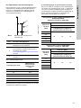
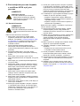
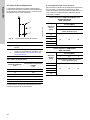
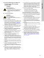
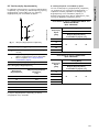
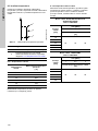
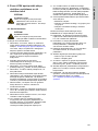
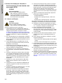
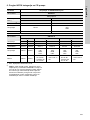
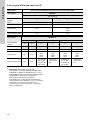
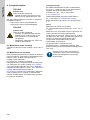
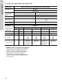
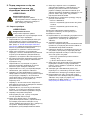
8.3 Temperature calculation
The illustration below shows the maximum surface
temperature of the pump as a result of the maximum
liquid temperature and temperature rise in the shaft
seal.
Fig. 4 Maximum surface temperature
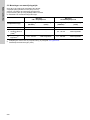
8.3.1 Temperature class
The maximum surface temperature for dust is stated
on the nameplate.
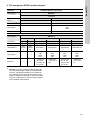
8.3.2 Shaft seal temperature
In order to calculate the pump surface temperature
and temperature class, the below tables show the
temperature rise in the shaft seal for different shaft
diameters, different pressure values and various
media classes.
TM06 4445 2315
Pos. Figure legend
1
Maximum surface temperature of the
pump
2
Temperature rise in the shaft seal.
Calculated by Grundfos. See section
8.3.2 Shaft seal temperature.
3 Maximum liquid temperature
Temperature class
Maximum surface
temperature
[°C]
T1 450
T2 300
T3 200
T4 135
T5 100
T6 85
1
2
3
Shaft seal: HQQx/HUUx/HQUx and
AUUx/AQQx/DQQx
Rpm: 2900/3500
Shaft
diameter
[mm]
Pressure [MPa]
12.54
Shaft seal temperature rise [°C]
12
22 24 26
16
22
28
36
Shaft seal: HQBx/HUBx
Rpm: 2900/3500
Shaft
diameter
[mm]
Pressure [MPa]
12.54
Shaft seal temperature rise [°C]
12
18 20 22
16
22
28
36

English (GB)
15
9. Before starting up and during
operation of an ATEX-approved
pump
9.1 Checklist
Observe this checklist:
1. Check that the ATEX rating of the motor, pump
and accessories corresponds to the specified
category. See section 6. Scope of ATEX
categories for CR pumps. If the motor, pump or
accessory categories differ, the lower rating is
valid.
2. If the pump falls under category M2, check that
the pump is protected by a guard to prevent
damage from falling or ejected objects.
3. Clean the cavities behind the pump's coupling
guard on a regular basis to avoid hazardous dust
deposits.
4. Check that the motor output power corresponds
to the required P
2
of the pump, see nameplates.
5. Check that the pump is as ordered, see
nameplates.
6. Check the axial alignment of the chamber stack.
See the label on the inside of the coupling guard.
Check that the shaft seal components, rubber
parts and seal surfaces are suitable for the
pumped liquid.
7. Check that the shaft can rotate freely. There must
be no mechanical contact between impeller and
chamber.
8. Check that the pump has been filled with liquid
and vented. The pump must never run dry.
9. Check the direction of rotation of the motor, see
the arrow on the top of the fan cover.
10. If you have chosen a pump with double seal,
back-to-back, check that the seal chamber is
pressurised. Always pressurise the chamber
during operation. Always use ATEX-approved
equipment.
11. If you have chosen a pump with double seal,
tandem, check that the seal chamber is
completely filled with liquid. The seal chamber
must always be filled with flushing liquid during
operation. The dry-running protection must be
ATEX-approved.
12. Follow the special startup procedures for these
pump types:
– MAGdrive pumps
– pumps with double seal, back-to-back
– pumps with double seal, tandem.
For further information, see the installation and
operating instructions for the pump in question.
13. Check that the liquid temperature never exceeds
the maximum liquid temperature, t
max
, stated on
the nameplate.
14. Avoid overheating of the pump.
Operation against a closed outlet valve may
cause overheating. Install a bypass with a
pressure relief non-return valve.
15. Check for abnormal noise during operation to
avoid overheating of the pump.
16. Re-vent the pump in either of these situations:
– the pump has been stopped for a period of
time.
– air has accumulated in the pump.
17. If the pump is with bearing bracket, check for
bearing noise every week. Replace the bearing if
it shows signs of wear.
18. The auto-ignition temperature of the pumped
liquid must be 50 K above the maximum surface
temperature of the pump.
19. Make sure to apply the correct inlet pressure.
Use the correct table for the vapour pressure for
the pumped liquid. See section
9.1.1 Specification and calculation of inlet
pressure.
DANGER
Explosion risk
Death or serious personal injury
- Do not run the pump at speeds
exceeding the rated speed. See pump
nameplate.
DANGER
Explosion risk
Death or serious personal injury
- Follow the checklist below.

English (GB)
16
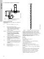
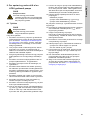
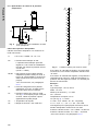
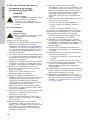
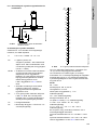
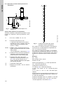
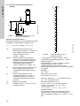
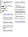
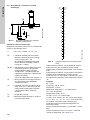
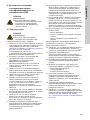
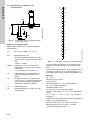
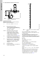
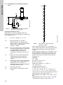
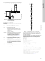
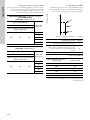
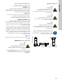
9.1.1 Specification and calculation of inlet
pressure
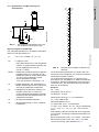
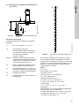
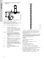
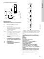
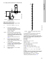
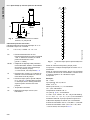
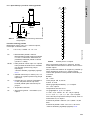
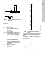
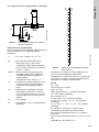
Fig. 5 Schematic view of open system with a
CR pump
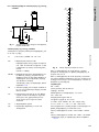
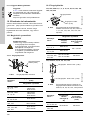
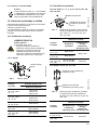
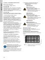
Calculation of inlet pressure
Calculate the maximum suction lift "H" in m head as
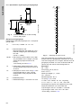
follows:
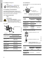
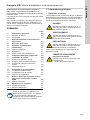
Fig. 6 Vapour pressure for water in m head
If the calculated "H" is positive, the pump can
operate at a suction lift of maximum "H" m head.
If the calculated "H" is negative, an inlet pressure of
minimum "H" m head is required. There must be a
pressure equal to the calculated "H" during
operation.
Example:
Pb = 1 bar.
Pump type: CR 15, 50 Hz.
Flow rate: 15 m
3
/h.
NPSH (see the appendix*): 1.1 m head.
Hf = 3.0 m head.
Liquid temperature: 60 °C.
Hv (see fig. 6): 2.1 m head.
H = Pb x 10.2 - NPSH - Hf - Hv - Hs [m head].
H = 1 x 10.2 - 1.1 - 3.0 - 2.1 - 0.5 = 3.5 m head.
This means that the pump can operate at a suction
lift of maximum 3.5 m head.
Pressure calculated in bar: 3.5 x 0.0981 = 0.343 bar.
Pressure calculated in kPa: 3.5 x 9.81 = 34.3 kPa.
*Link to appendix, see section 9.1.2.
TM02 0118 3800
H = Pb x 10.2 - NPSH - Hf - Hv - Hs
Pb = Barometric pressure in bar.
Barometric pressure can be set to 1 bar.
In closed systems, Pb indicates the
system pressure in bar.
(10 bar = 1 MPa)
NPSH = Net Positive Suction Head in m head, to
be read from the NPSH curve in the
appendix* (at the highest flow rate the
pump will be delivering).
*Link to appendix, see section 9.1.2.
Hf = Friction loss in the inlet pipe in m head
at the highest flow rate the pump will be
delivering.
Hv = Vapour pressure for water in m head.
See fig. 6. If the pumped liquid is not
water, then use the vapour pressure for
the liquid which is being pumped.
tm = Liquid temperature.
Hs = Safety margin = minimum 0.5 m head.
Hv
H
NPSH
Pb
Hf
TM02 7445 3503
20
15
12
10
8,0
6,0
5,0
4,0
3,0
2,0
1,0
0,8
0,6
0,4
0,3
0,2
0,1
1,5
120
110
90
100
80
70
60
50
40
30
20
10
0
Hv
(m)
tm
(°C)
150
130
140
25
35
45
40
30
160
170
180
190
62
79
100
126

English (GB)
17
9.1.2 Appendix with NPSH curves
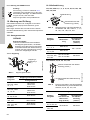
10. Maintenance and inspection
Service documentation is available in Grundfos
Product Center (http://product-
selection.grundfos.com/).
If you have any questions, please contact the
nearest Grundfos company or service workshop.
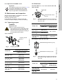
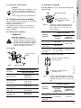
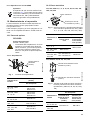
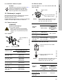
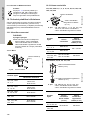
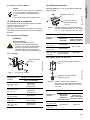
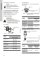
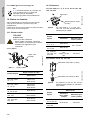
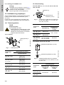
10.1 Tightening torques
10.1.1 Coupling
Fig. 7 Coupling screws
10.2 Shaft seal
CR, CRI, CRN 1s, 1, 3, 5, 10, 15, 20, 95, 125, 155,
185, 215, 255
Fig. 8 Shaft seal and shaft seal set screws for
CR, CRI, CRN 1s, 1, 3, 5, 95, 125, 155,
185, 215, 255
CR, CRN 32, 45, 64, 90, 120, 150
Fig. 9 Shaft seal flange screws and shaft seal
set screws for CR, CRN 32, 45, 64, 90,
120, 150
Appendix:
The appendix referred to in section 9.1.1 is
found in the standard CR, CRI, CRN
installation and operating instructions:
http://net.grundfos.com/qr/i/96462123
DANGER
Explosion risk
Death or serious personal injury
- The coupling screws, shaft seal, shaft
seal flange screws and shaft seal set
screws must be tightened according to
the specified torque values.
TM07 2396 3418
Pump size
Coupling screws (4 pcs)
Tightening torque
CR, CRI, CRN
1s, 1, 3
M6-13 Nm
M8-31 Nm
M10-61 Nm
CR, CRI, CRN
10, 15, 20
M6-13 Nm
M8-31 Nm
M10-62 Nm
CR, CRI, CRN
32, 45, 64, 90
M10-85 Nm
CR, CRI, CRN
120, 150
M10-85 Nm
M16-100 Nm
CR, CRN 95,
125, 155, 185,
215, 255
M10-85 Nm
M16-100 Nm
Coupling screw
(4 pcs)
TM07 2395 3418
Pump size
Tightening torque
Shaft seal
Shaft seal set
screws (3 pcs)
CR, CRI, CRN
1s, 1, 3, 5
M28-35 Nm
M5 - 2.5 Nm
CR, CRI, CRN
10, 15, 20
M33-35 Nm
CR, CRN 95,
125, 155, 185,
215, 255
Hex 60-100 Nm
Hex 75-150 Nm
M6-6 Nm
TM07 2397 3418
Pump size
Tightening torque
Shaft seal
flange screws
(4 pcs)
Shaft seal set
screws (3 pcs)
CR, CRI, CRN
32, 45, 64, 90
M10-62 Nm M6-6 Nm
CR, CRI, CRN
120, 150
Shaft seal
Shaft seal set screw
(3 pcs)
Shaft seal set screw (3 pcs)
Shaft seal flange screw (4 pcs)

Български (BG)
18
Български (BG) Упътване за монтаж и експлоатация
Превод на оригиналната английска версия
Тези допълнителни инструкции за монтаж и
експлоатация се отнасят за сертифицираните по
ATEX CR помпи на Grundfos.
Помпите CR отговарят на ATEX Директива 2014/
34/EС.
Помпите са подходящи за употреба в зони,
класифицирани по Директива 1999/92/ЕС. При
съмнение сверете с упоменатите по-горе
директиви или се свържете с Grundfos.
СЪДЪРЖАНИЕ
Стр.
1. Обща информация
1.1 Предупредителни текстове за
опасност
В инструкциите за монтаж и експлоатация,
инструкциите за безопасност и сервизните
инструкции на Grundfos може да се появяват
символите и предупредителните текстове за
опасност по-долу.
Предупредителните текстове за опасност са
структурирани по следния начин:
1. Обща информация
18
1.1 Предупредителни текстове за опасност
18
1.2 Бележки
19
2. Сродни инструкции за монтаж и
експлоатация
19
3. Получаване на продукта
19
4. Документ за взривобезопасност
19
5. Идентификация
20
5.1 Табелка с данни
20
5.2 Обозначение за тип
21
5.3 Лагер на задвижващия край на
двигателя
22
6. Обхват на ATEX категориите за CR
помпи
23
7. Инсталиране на продукта
24
7.1 Помпи с единично уплътнение
24
7.2 Помпа с MAGdrive
24
7.3 Помпа с двойно уплътнение
25
7.4 Помпи с необорудван вал
25
8. Работни условия
26
8.1 Максимална околна температура
26
8.2 Максимална температура на течността
26
8.3 Пресмятане на температурата
27
9. Преди пускането и по време на
работа на сертифицирана по ATEX
помпа
28
9.1 Списък със задачи
28
10. Поддръжка и огледи
30
10.1 Моменти на затягане
30
10.2 Уплътнение на вала
30
Преди инсталиране прочетете този
документ. Монтажът и експлоатацията
трябва да отговарят на местната
нормативна уредба и утвърдените
правила за добра практика.
ОПАСНОСТ
Обозначава опасна ситуация, която
може да доведе до смърт или тежки
наранявания.
ПРЕДУПРЕЖДЕНИЕ
Обозначава опасна ситуация, която
може да доведе до смърт или тежки
наранявания.
ВНИМАНИЕ
Обозначава опасна ситуация, която
може да доведе до смърт или тежки
наранявания.
СИГНАЛИЗИРАЩА ДУМА
Описание на опасността
Последствия от пренебрегването на
предупреждението.
- Действия за предотвратяване на
опасността.

Български (BG)
19
1.2 Бележки
В инструкциите за монтаж и експлоатация,
инструкциите за безопасност и сервизните
инструкции на Grundfos може да се появяват
символите и бележките по-долу.
2. Сродни инструкции за монтаж и
експлоатация
"X" на табелката с данни показва, че
оборудването е предмет на специални условия за
безопасна употреба, както е описано в тези
инструкции. Маркировките на табелката с данни
са описани в таблицата в раздел
5. Идентификация.
В допълнение към тези инструкции, трябва също
да се спазват и следните инструкции за монтаж и
експлоатация:
• CR, CRI, CRN: за стандартни помпи
• CR, CRI, CRN, CRT: демонтаж на
транспортната скоба и монтаж на двигателя.
За помпи без двигател
• MG: стандартни двигатели на Grundfos.
При специални версии на помпите CR
съблюдавайте съответните инструкции за монтаж
и експлоатация:
•CRN MAGdrive
• CR, CRI, CRN: двойно уплътнение, гръб-към-
гръб
• CR, CRI, CRN: двойно уплътнение, тандемно
• MG: стандартни двигатели на Grundfos.
3. Получаване на продукта
Ако помпата е доставена без двигател,
монтирайте двигателя и след това регулирайте
комплекта камери и уплътнението на вала в
съответствие с процедурата, описана в
инструкциите за монтаж и експлоатация -
"Демонтаж на транспортната скоба и монтаж на
двигателя", съпровождащи помпата.
4. Документ за взривобезопасност
Комбинацията от CR помпа и цялото оборудване
за мониторинг трябва да бъдат описани в
документа за взривобезопасност съгласно
Директива 1999/92/ЕС.
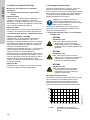
Съблюдавайте тези инструкции при
работа с взривобезопасни продукти.
Син или сив кръг с бял графичен символ
обозначава, че за избягване на
опасността трябва да се предприеме
действие.
Червен или сив кръг с диагонална
лента, обикновено с черен графичен
символ, обозначава, че определено
действие трябва да не се предприема
или да бъде преустановено.
Неспазването на тези инструкции може
да доведе до неизправност или повреда
на оборудването.
Съвети и препоръки, които улесняват
работата.

Български (BG)
20
5. Идентификация
5.1 Табелка с данни
Табелката с данни върху силовата глава на
помпата дава следната информация:
• данни за стандартна помпа
• данни за ATEX маркировката
– номер на техническото досие
– сериен номер
– Ex категория.
Фиг. 1 Пример за табелка на CR помпа,
сертифицирана по ATEX
Данните за АТЕХ маркировката се отнасят само
за частта, включително куплунга. Двигателят има
отделна табелка с данни.
TM07 5039 0719
DK-8850 Bjerringbro,Denmark
Model-PN-SN
Type
Hz
pmax/tmax
Tech file no
Made in Denmark
P code: P115482
bar/°C
min
-1
excl.motor 500kg
/hm
3
kW [P2]
H/H max m 0(,
ȘS
B-96123526-98438832
CR255-1-1A-F-A-E-HQQE
435/248
2917
64
CCW
98964685X
99356347
50/60
4.0
0.7 69.7
14.2/22.1
21
435-580/176
II 3G Ex h IIC T4...T3 Gb
АТЕХ класификация
Поз. Описание
1
II
Група
I: Подземно в мини
II: Повърхностно
оборудване
3G
Категория
M2: Минно дело
2G, 3G: Газ/изпарения
2D, 3D: Прах
Ex h Тип защита
IIC
Група околна среда
IIC: Газ/изпарения
IIIC: Запалим прах
IIIB: Немагнитен прах
T4...T3
Максимална повърхностна
температура според 80079-
36.
Диапазон на температурата
или специфична
температура.
T4...T3: Газ
T125 °C: Прах
Gb
EPL (Equipment Protection
Level).
Gb, Gc: Газ
Db, Dc: Прах
2
98964685
Номер на файла за
техническото досие,
съхранявано в DEKRA.
X
Указва, че за оборудването
важат специални условия
за безопасна употреба.
Условията са упоменати в
този документ.
Pagina se încarcă...
Pagina se încarcă...
Pagina se încarcă...
Pagina se încarcă...
Pagina se încarcă...
Pagina se încarcă...
Pagina se încarcă...
Pagina se încarcă...
Pagina se încarcă...
Pagina se încarcă...
Pagina se încarcă...
Pagina se încarcă...
Pagina se încarcă...
Pagina se încarcă...
Pagina se încarcă...
Pagina se încarcă...
Pagina se încarcă...
Pagina se încarcă...
Pagina se încarcă...
Pagina se încarcă...
Pagina se încarcă...
Pagina se încarcă...
Pagina se încarcă...
Pagina se încarcă...
Pagina se încarcă...
Pagina se încarcă...
Pagina se încarcă...
Pagina se încarcă...
Pagina se încarcă...
Pagina se încarcă...
Pagina se încarcă...
Pagina se încarcă...
Pagina se încarcă...
Pagina se încarcă...
Pagina se încarcă...
Pagina se încarcă...
Pagina se încarcă...
Pagina se încarcă...
Pagina se încarcă...
Pagina se încarcă...
Pagina se încarcă...
Pagina se încarcă...
Pagina se încarcă...
Pagina se încarcă...
Pagina se încarcă...
Pagina se încarcă...
Pagina se încarcă...
Pagina se încarcă...
Pagina se încarcă...
Pagina se încarcă...
Pagina se încarcă...
Pagina se încarcă...
Pagina se încarcă...
Pagina se încarcă...
Pagina se încarcă...
Pagina se încarcă...
Pagina se încarcă...
Pagina se încarcă...
Pagina se încarcă...
Pagina se încarcă...
Pagina se încarcă...
Pagina se încarcă...
Pagina se încarcă...
Pagina se încarcă...
Pagina se încarcă...
Pagina se încarcă...
Pagina se încarcă...
Pagina se încarcă...
Pagina se încarcă...
Pagina se încarcă...
Pagina se încarcă...
Pagina se încarcă...
Pagina se încarcă...
Pagina se încarcă...
Pagina se încarcă...
Pagina se încarcă...
Pagina se încarcă...
Pagina se încarcă...
Pagina se încarcă...
Pagina se încarcă...
Pagina se încarcă...
Pagina se încarcă...
Pagina se încarcă...
Pagina se încarcă...
Pagina se încarcă...
Pagina se încarcă...
Pagina se încarcă...
Pagina se încarcă...
Pagina se încarcă...
Pagina se încarcă...
Pagina se încarcă...
Pagina se încarcă...
Pagina se încarcă...
Pagina se încarcă...
Pagina se încarcă...
Pagina se încarcă...
Pagina se încarcă...
Pagina se încarcă...
Pagina se încarcă...
Pagina se încarcă...
Pagina se încarcă...
Pagina se încarcă...
Pagina se încarcă...
Pagina se încarcă...
Pagina se încarcă...
Pagina se încarcă...
Pagina se încarcă...
Pagina se încarcă...
Pagina se încarcă...
Pagina se încarcă...
Pagina se încarcă...
Pagina se încarcă...
Pagina se încarcă...
Pagina se încarcă...
Pagina se încarcă...
Pagina se încarcă...
Pagina se încarcă...
Pagina se încarcă...
Pagina se încarcă...
Pagina se încarcă...
Pagina se încarcă...
Pagina se încarcă...
Pagina se încarcă...
Pagina se încarcă...
Pagina se încarcă...
Pagina se încarcă...
Pagina se încarcă...
Pagina se încarcă...
Pagina se încarcă...
Pagina se încarcă...
Pagina se încarcă...
Pagina se încarcă...
Pagina se încarcă...
Pagina se încarcă...
Pagina se încarcă...
Pagina se încarcă...
Pagina se încarcă...
Pagina se încarcă...
Pagina se încarcă...
Pagina se încarcă...
Pagina se încarcă...
Pagina se încarcă...
Pagina se încarcă...
Pagina se încarcă...
Pagina se încarcă...
Pagina se încarcă...
Pagina se încarcă...
Pagina se încarcă...
Pagina se încarcă...
Pagina se încarcă...
Pagina se încarcă...
Pagina se încarcă...
Pagina se încarcă...
Pagina se încarcă...
Pagina se încarcă...
Pagina se încarcă...
Pagina se încarcă...
Pagina se încarcă...
Pagina se încarcă...
Pagina se încarcă...
Pagina se încarcă...
Pagina se încarcă...
Pagina se încarcă...
Pagina se încarcă...
Pagina se încarcă...
Pagina se încarcă...
Pagina se încarcă...
Pagina se încarcă...
Pagina se încarcă...
Pagina se încarcă...
Pagina se încarcă...
Pagina se încarcă...
Pagina se încarcă...
Pagina se încarcă...
Pagina se încarcă...
Pagina se încarcă...
Pagina se încarcă...
Pagina se încarcă...
Pagina se încarcă...
Pagina se încarcă...
Pagina se încarcă...
Pagina se încarcă...
Pagina se încarcă...
Pagina se încarcă...
Pagina se încarcă...
Pagina se încarcă...
Pagina se încarcă...
Pagina se încarcă...
Pagina se încarcă...
Pagina se încarcă...
Pagina se încarcă...
Pagina se încarcă...
Pagina se încarcă...
Pagina se încarcă...
Pagina se încarcă...
Pagina se încarcă...
Pagina se încarcă...
Pagina se încarcă...
Pagina se încarcă...
Pagina se încarcă...
Pagina se încarcă...
Pagina se încarcă...
Pagina se încarcă...
Pagina se încarcă...
Pagina se încarcă...
Pagina se încarcă...
Pagina se încarcă...
Pagina se încarcă...
Pagina se încarcă...
Pagina se încarcă...
Pagina se încarcă...
Pagina se încarcă...
Pagina se încarcă...
Pagina se încarcă...
Pagina se încarcă...
Pagina se încarcă...
Pagina se încarcă...
Pagina se încarcă...
Pagina se încarcă...
Pagina se încarcă...
Pagina se încarcă...
Pagina se încarcă...
Pagina se încarcă...
Pagina se încarcă...
Pagina se încarcă...
Pagina se încarcă...
Pagina se încarcă...
Pagina se încarcă...
Pagina se încarcă...
Pagina se încarcă...
Pagina se încarcă...
Pagina se încarcă...
Pagina se încarcă...
Pagina se încarcă...
Pagina se încarcă...
Pagina se încarcă...
Pagina se încarcă...
Pagina se încarcă...
Pagina se încarcă...
Pagina se încarcă...
Pagina se încarcă...
Pagina se încarcă...
Pagina se încarcă...
Pagina se încarcă...
Pagina se încarcă...
Pagina se încarcă...
Pagina se încarcă...
Pagina se încarcă...
Pagina se încarcă...
Pagina se încarcă...
Pagina se încarcă...
Pagina se încarcă...
Pagina se încarcă...
Pagina se încarcă...
Pagina se încarcă...
Pagina se încarcă...
Pagina se încarcă...
Pagina se încarcă...
Pagina se încarcă...
Pagina se încarcă...
Pagina se încarcă...
Pagina se încarcă...
Pagina se încarcă...
Pagina se încarcă...
Pagina se încarcă...
Pagina se încarcă...
Pagina se încarcă...
Pagina se încarcă...
Pagina se încarcă...
Pagina se încarcă...
Pagina se încarcă...
Pagina se încarcă...
Pagina se încarcă...
Pagina se încarcă...
Pagina se încarcă...
Pagina se încarcă...
Pagina se încarcă...
Pagina se încarcă...
Pagina se încarcă...
Pagina se încarcă...
Pagina se încarcă...
Pagina se încarcă...
Pagina se încarcă...
Pagina se încarcă...
Pagina se încarcă...
Pagina se încarcă...
Pagina se încarcă...
Pagina se încarcă...
Pagina se încarcă...
Pagina se încarcă...
Pagina se încarcă...
Pagina se încarcă...
Pagina se încarcă...
Pagina se încarcă...
Pagina se încarcă...
Pagina se încarcă...
Pagina se încarcă...
Pagina se încarcă...
Pagina se încarcă...
Pagina se încarcă...
Pagina se încarcă...
Pagina se încarcă...
Pagina se încarcă...
Pagina se încarcă...
Pagina se încarcă...
Pagina se încarcă...
Pagina se încarcă...
Pagina se încarcă...
Pagina se încarcă...
Pagina se încarcă...
Pagina se încarcă...
Pagina se încarcă...
Pagina se încarcă...
Pagina se încarcă...
Pagina se încarcă...
Pagina se încarcă...
Pagina se încarcă...
Pagina se încarcă...
Pagina se încarcă...
Pagina se încarcă...
Pagina se încarcă...
Pagina se încarcă...
Pagina se încarcă...
Pagina se încarcă...
Pagina se încarcă...
Pagina se încarcă...
Pagina se încarcă...
Pagina se încarcă...
Pagina se încarcă...
Pagina se încarcă...
Pagina se încarcă...
Pagina se încarcă...
Pagina se încarcă...
Pagina se încarcă...
Pagina se încarcă...
Pagina se încarcă...
Pagina se încarcă...
Pagina se încarcă...
Pagina se încarcă...
Pagina se încarcă...
Pagina se încarcă...
Pagina se încarcă...
Pagina se încarcă...
Pagina se încarcă...
Pagina se încarcă...
Pagina se încarcă...
Pagina se încarcă...
Pagina se încarcă...
Pagina se încarcă...
Pagina se încarcă...
Pagina se încarcă...
Pagina se încarcă...
Pagina se încarcă...
Pagina se încarcă...
Pagina se încarcă...
Pagina se încarcă...
Pagina se încarcă...
Pagina se încarcă...
Pagina se încarcă...
Pagina se încarcă...
Pagina se încarcă...
Pagina se încarcă...
Pagina se încarcă...
Pagina se încarcă...
-
 1
1
-
 2
2
-
 3
3
-
 4
4
-
 5
5
-
 6
6
-
 7
7
-
 8
8
-
 9
9
-
 10
10
-
 11
11
-
 12
12
-
 13
13
-
 14
14
-
 15
15
-
 16
16
-
 17
17
-
 18
18
-
 19
19
-
 20
20
-
 21
21
-
 22
22
-
 23
23
-
 24
24
-
 25
25
-
 26
26
-
 27
27
-
 28
28
-
 29
29
-
 30
30
-
 31
31
-
 32
32
-
 33
33
-
 34
34
-
 35
35
-
 36
36
-
 37
37
-
 38
38
-
 39
39
-
 40
40
-
 41
41
-
 42
42
-
 43
43
-
 44
44
-
 45
45
-
 46
46
-
 47
47
-
 48
48
-
 49
49
-
 50
50
-
 51
51
-
 52
52
-
 53
53
-
 54
54
-
 55
55
-
 56
56
-
 57
57
-
 58
58
-
 59
59
-
 60
60
-
 61
61
-
 62
62
-
 63
63
-
 64
64
-
 65
65
-
 66
66
-
 67
67
-
 68
68
-
 69
69
-
 70
70
-
 71
71
-
 72
72
-
 73
73
-
 74
74
-
 75
75
-
 76
76
-
 77
77
-
 78
78
-
 79
79
-
 80
80
-
 81
81
-
 82
82
-
 83
83
-
 84
84
-
 85
85
-
 86
86
-
 87
87
-
 88
88
-
 89
89
-
 90
90
-
 91
91
-
 92
92
-
 93
93
-
 94
94
-
 95
95
-
 96
96
-
 97
97
-
 98
98
-
 99
99
-
 100
100
-
 101
101
-
 102
102
-
 103
103
-
 104
104
-
 105
105
-
 106
106
-
 107
107
-
 108
108
-
 109
109
-
 110
110
-
 111
111
-
 112
112
-
 113
113
-
 114
114
-
 115
115
-
 116
116
-
 117
117
-
 118
118
-
 119
119
-
 120
120
-
 121
121
-
 122
122
-
 123
123
-
 124
124
-
 125
125
-
 126
126
-
 127
127
-
 128
128
-
 129
129
-
 130
130
-
 131
131
-
 132
132
-
 133
133
-
 134
134
-
 135
135
-
 136
136
-
 137
137
-
 138
138
-
 139
139
-
 140
140
-
 141
141
-
 142
142
-
 143
143
-
 144
144
-
 145
145
-
 146
146
-
 147
147
-
 148
148
-
 149
149
-
 150
150
-
 151
151
-
 152
152
-
 153
153
-
 154
154
-
 155
155
-
 156
156
-
 157
157
-
 158
158
-
 159
159
-
 160
160
-
 161
161
-
 162
162
-
 163
163
-
 164
164
-
 165
165
-
 166
166
-
 167
167
-
 168
168
-
 169
169
-
 170
170
-
 171
171
-
 172
172
-
 173
173
-
 174
174
-
 175
175
-
 176
176
-
 177
177
-
 178
178
-
 179
179
-
 180
180
-
 181
181
-
 182
182
-
 183
183
-
 184
184
-
 185
185
-
 186
186
-
 187
187
-
 188
188
-
 189
189
-
 190
190
-
 191
191
-
 192
192
-
 193
193
-
 194
194
-
 195
195
-
 196
196
-
 197
197
-
 198
198
-
 199
199
-
 200
200
-
 201
201
-
 202
202
-
 203
203
-
 204
204
-
 205
205
-
 206
206
-
 207
207
-
 208
208
-
 209
209
-
 210
210
-
 211
211
-
 212
212
-
 213
213
-
 214
214
-
 215
215
-
 216
216
-
 217
217
-
 218
218
-
 219
219
-
 220
220
-
 221
221
-
 222
222
-
 223
223
-
 224
224
-
 225
225
-
 226
226
-
 227
227
-
 228
228
-
 229
229
-
 230
230
-
 231
231
-
 232
232
-
 233
233
-
 234
234
-
 235
235
-
 236
236
-
 237
237
-
 238
238
-
 239
239
-
 240
240
-
 241
241
-
 242
242
-
 243
243
-
 244
244
-
 245
245
-
 246
246
-
 247
247
-
 248
248
-
 249
249
-
 250
250
-
 251
251
-
 252
252
-
 253
253
-
 254
254
-
 255
255
-
 256
256
-
 257
257
-
 258
258
-
 259
259
-
 260
260
-
 261
261
-
 262
262
-
 263
263
-
 264
264
-
 265
265
-
 266
266
-
 267
267
-
 268
268
-
 269
269
-
 270
270
-
 271
271
-
 272
272
-
 273
273
-
 274
274
-
 275
275
-
 276
276
-
 277
277
-
 278
278
-
 279
279
-
 280
280
-
 281
281
-
 282
282
-
 283
283
-
 284
284
-
 285
285
-
 286
286
-
 287
287
-
 288
288
-
 289
289
-
 290
290
-
 291
291
-
 292
292
-
 293
293
-
 294
294
-
 295
295
-
 296
296
-
 297
297
-
 298
298
-
 299
299
-
 300
300
-
 301
301
-
 302
302
-
 303
303
-
 304
304
-
 305
305
-
 306
306
-
 307
307
-
 308
308
-
 309
309
-
 310
310
-
 311
311
-
 312
312
-
 313
313
-
 314
314
-
 315
315
-
 316
316
-
 317
317
-
 318
318
-
 319
319
-
 320
320
-
 321
321
-
 322
322
-
 323
323
-
 324
324
-
 325
325
-
 326
326
-
 327
327
-
 328
328
-
 329
329
-
 330
330
-
 331
331
-
 332
332
-
 333
333
-
 334
334
-
 335
335
-
 336
336
-
 337
337
-
 338
338
-
 339
339
-
 340
340
-
 341
341
-
 342
342
-
 343
343
-
 344
344
-
 345
345
-
 346
346
-
 347
347
-
 348
348
-
 349
349
-
 350
350
-
 351
351
-
 352
352
-
 353
353
-
 354
354
-
 355
355
-
 356
356
-
 357
357
-
 358
358
-
 359
359
-
 360
360
-
 361
361
-
 362
362
-
 363
363
-
 364
364
-
 365
365
-
 366
366
-
 367
367
-
 368
368
-
 369
369
-
 370
370
-
 371
371
-
 372
372
-
 373
373
-
 374
374
-
 375
375
-
 376
376
-
 377
377
-
 378
378
-
 379
379
-
 380
380
-
 381
381
-
 382
382
-
 383
383
-
 384
384


Grundfos CR series Installation And Operating Instructions Manual
- Tip
- Installation And Operating Instructions Manual
- Acest manual este potrivit și pentru
în alte limbi
- slovenčina: Grundfos CR series
Lucrări înrudite
-
Grundfos CRT Installation And Operating Instructions Manual
-
Grundfos CR 1 Installation And Operating Instructions Manual
-
-
Grundfos MTR 8 Installation And Operating Instructions, Supplement
-
-
Grundfos APG.50.12.1 Installation And Operating Instructions Manual
-
-
-
-
Alte documente
-
SICK General Safety Notes ATEX Devices Presence Detection Instrucțiuni de utilizare
-
-
Wilo Yonos PICO1.0 Manual de utilizare
-
ESBE CRC217 Instrucțiuni de utilizare
-
Sulzer Channel Monster™ – CDD-XDS2.0 Installation, Operating And Maintenance Instructions
-
-
-
Emerson MSM400 Manual de utilizare
-
 JBM 54299 Manualul utilizatorului
-
Comet APS 61 – 71 Manual de utilizare
