Ransomes 62298 62299 62857 62858 62859 62860 62861 62862 62863 62864 62865 62866 62867 62868 Accessories Manual
- Tip
- Accessories Manual

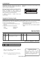
Instruction Sheet
WARNING
Warning: If incorrectly used, this machine can
cause severe injury. Those who use and maintain
this machine should be trained in its proper use,
warned of its dangers, and must read the entire
manual before attempting to set up, operate, adjust,
or service the machine.
GB
18 Inch TrueSet
™
Reels
62857 – 18 in. Left Hand 11 Blade Greens Reel
62858 – 18 in. Left Hand 15 Blade Greens Reel
62298 – 18 in. Left Hand 8 Blade Fairway Reel
62859 – 18 in. Right Hand 8 Blade Fairway Reel
62299 – 18 in. Left Hand 11 Blade Fairway Reel
62860 – 18 in. Right Hand 11 Blade Fairway Reel
22 Inch TrueSet
™
Reels
62861 – 22 in. Left Hand 7 Blade Reel
62862 – 22 in. Right Hand 7 Blade Reel
62863 – 22 in. Left Hand 9 Blade Reel
62864 – 22 in. Right Hand 9 Blade Reel
62865 – 22 in. Left Hand 11 Blade Reel
62866 – 22 in. Right Hand 11 Blade Reel
62867 – 22 in. Left Hand 15 Blade Reel
62868 – 22 in. Right Hand 15 Blade Reel
Reel Mounting Kits (Single Reel)
4395138 – 18 in. Hydraulic Drive Reel
4395139 – 18 in. Electric Drive Reel
4395140 – 22 in. Hydraulic Drive Fairway Reel
4395141 – 22 in. Electric Drive Fairway Reel
4395142 – 22 in. Hydraulic Drive Greens Reel
4395143 – 22 in. Electric Drive Greens Reel
4387946-Rev A

This manual contains adjustment, maintenance,
troubleshooting instructions, and parts list for your new
Jacobsen reel. This manual should be stored with the
mower for reference during operation.
Before you operate your mower, you and each operator
you employ should read the manual carefully in its
entirety. By following the safety, operating, and
maintenance instructions, you will prolong the life of your
mower and maintain its maximum efficiency.
If additional information is needed, contact your
Jacobsen Dealer.
The serial plate is attached to the reel frame. Jacobsen
recommends you record these numbers below for easy
reference.
CHARLOTTE, NC PRODUCT OF U.S.A.
®
A Textron Company
2
Proposition 65 Warning
This product contains or emits
chemicals known to the State of
California to cause cancer and birth
defects or other reproductive harm.
FOREWORD
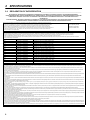
Suggested Stocking Guide
To keep your mower fully operational and productive, Jacobsen suggests you maintain a stock of the more commonly
used maintenance items. We have included part numbers for additional support materials and training aids.
To order any of the following material:
1. Write your full name and complete address on your
order form.
2. Explain where and how to make shipment:
❑
UPS ❑ Regular
Mail
❑
O
vernight ❑
2n
d Day
3. Order by the quantity desired, the part number, and
the description of the part.
4. Send or bring the order to your authorized Jacobsen
Dealer.
Service Parts
Service Support Material
Qty. Part No. Description Qty. Part No. Description
4252470 Bedknife Screw (100 Pack)
400074 Hair Pin, 5/64 x 1/4 x 1-3/16”
Qty. Part No. Description
4269792 5 in. Reel Technical Repair Manual
Litho in U.S.A. 9-2017
© 2017, Jacobsen, A Textron Company/Textron Innovations Inc.
“All rights reserved, including the right to reproduce this material
or portions thereof in any form.”
These are the original instructions verified by
Jacobsen, A Textron Company.

3
Table of Contents
1 Safety
1.1 Operating Safety............................................... 4
1.2 Important Safety Notes ..................................... 5
2 Specifications
2.1 Product Identification ........................................ 6
2.2 Cutting Units ..................................................... 6
2.3 Accessories & Support Literature ..................... 6
2.4 Declaration of Incorporation ............................. 8
3Setup
3.1 General information ........................................ 10
3.2 Reel Accessories ............................................ 10
3.3 Reel to Mower Assembly ................................ 10
3.4 Electric Reel Motor ......................................... 11
3.5 Hydraulic Reel Motor ...................................... 11
3.6 Reel Stop (Greens Reel) ................................ 11
3.7 Down Pressure (Fairway Reel) ....................... 12
3.8 Counterweight ................................................ 12
4 Adjustments
4.1 General........................................................... 13
4.2 Bedknife-To-Reel ............................................ 13
4.3 Bedknife Adjustment ....................................... 14
4.4 Cutting Height ................................................. 14
4.5 Reel Bearing ................................................... 15
4.6 Bedknife Adjuster Spring ................................ 15
4.7 Bedknife Adjuster Tension .............................. 15
4.8 Grinding Bedknife ........................................... 16
4.9 Down Pressure Spring .................................... 16
4.10 Torque Specification ....................................... 17
6.1 Outer Reel ...................................................... 18
7.1 Inner Reel ....................................................... 20
6.1 Mounting Kits .................................................. 22

1 SAFETY
4
1 SAFETY
1.1 OPERATING SAFETY ______________________________________________________
1. Safety is dependent upon the awareness, concern
and prudence of those who operate or service the
equipment. Never allow minors to operate any
equipment.
2. It is your responsibility to read this manual and all
publications associated with this equipment (Safety &
Operation Manual, Engine Manual, and attachments/
accessories instruction sheets). If the operator
cannot read English it is the owner’s responsibility to
explain the material contained in this manual to them.
3. Learn the proper use of the machine, the location
and purpose of all the controls and gauges before
you operate the equipment. Working with unfamiliar
equipment can lead to accidents.
4. Never allow anyone to operate or service the
machine or its attachments without proper training
and instructions; or while under the influence of
alcohol or drugs.
5. Wear all the necessary protective clothing and
personal safety devices to protect your head, eyes,
ears, hands, and feet. Operate the machine only in
daylight or in good artificial light.
6. Evaluate the terrain to determine what accessories
and attachments are needed to properly and safely
perform the job. Only use accessories and
attachments approved by Jacobsen.
7. Stay alert for holes in the terrain and other hidden
hazards.
8. Inspect the area where the equipment will be used.
Pick up all the debris you can find before operating.
Beware of overhead obstructions (low tree limbs,
electrical wires, etc.) and also underground obstacles
(sprinklers, pipes, tree roots, etc.). Enter a new area
cautiously. Stay alert for hidden hazards.
9. Never direct discharge of material toward bystanders,
nor allow anyone near the machine while in
operation. The owner/operator can prevent and is
responsible for injuries inflicted to themselves, to
bystanders, and damage to property.
10. Do not carry passengers. Keep bystanders and pets
a safe distance away.
11. Never operate equipment that is not in perfect
working order or is without decals, guards, shields,
discharge deflectors, or other protective devices
securely fastened in place.
12. Never disconnect or bypass any switch.
13. Do not change the engine governor setting or
overspeed the engine.
14. Carbon monoxide in the exhaust fumes can be fatal
when inhaled. Never operate the engine without
proper ventilation or in an enclosed area.
15. Fuel is highly flammable; handle with care.
16. Keep the engine clean. Allow the engine to cool
before storing and always remove the ignition key.
17. Disengage all drives and engage parking brake
before starting the engine (motor). Start the engine
only when sitting in operator’s seat, never while
standing beside the unit.
18. Equipment must comply with the latest federal, state,
and local requirements when driven or transported
on public roads. Watch out for traffic when crossing
or operating on or near roads.
19. Local regulations may restrict the age of the operator.
20. Never use your hands to search for oil leaks.
Hydraulic fluid under pressure can penetrate the skin
and cause serious injury.
21. Operate the machine up and down the face of slopes
(vertically), not across the face (horizontally).
22. To prevent tipping or loss of control, do not start or
stop suddenly on slopes. Reduce speed when
making sharp turns. Use caution when changing
directions.
23. Always use the seat belt when operating mowers
equipped with a Roll Over Protective Structure
(ROPS).
Never use a seat belt when operating mowers
without a ROPS.
24. Always disconnect battery cables from battery before
performing any welding operation on the mower.
This machine is to be operated and maintained as specified in this manual and is intended for the professional
maintenance of specialized turf grasses. It is not intended for use on rough terrain or long grasses.
WARNING
EQUIPMENT OPERATED IMPROPERLY OR BY UNTRAINED PERSONNEL CAN BE DANGEROUS.
Familiarize yourself with the location and proper use of all controls. Inexperienced operators should receive
instruction from someone familiar with the equipment before being allowed to operate the machine.
!

SAFETY 1
5
1.2 IMPORTANT SAFETY NOTES ________________________________________________
This safety alert symbol is used to alert you to potential hazards.
DANGER - Indicates an imminently hazardous situation which, if not avoided, WILL result in death or serious injury.
WARNING - Indicates a potentially hazardous situation which, if not avoided, COULD result in death or serious
injury.
CAUTION - Indicates a potentially hazardous situation which, if not avoided, MAY result in minor or moderate injury
and property damage. It may also be used to alert against unsafe practices.
NOTICE - Indicates a potentially hazardous situation which, if not avoided, MAY result in property damage. It may
also be used to alert against unsafe practices.
For pictorial clarity, some illustrations in this manual may show shields, guards or plates open, or removed. Under no
circumstances should this equipment be operated without these devices securely fastened in place.
By following all instructions in this manual, you will prolong the life of your machine and maintain its maximum
efficiency. Adjustments and maintenance should always be performed by a qualified technician.
If additional information or service is needed, contact your Authorized Jacobsen Dealer who is kept informed of the
latest methods to service this equipment and can provide prompt and efficient service.
WARNING
The Interlock System on this mower prevents the mower from starting unless
the parking brake is engaged, reel levers are off, and traction lever is in
Neutral. The system will stop the engine if the operator leaves the seat
without engaging the parking brake, setting the reel levers to off, and placing
traction lever in Neutral.
NEVER operate mower unless the Interlock System is working.
!
WARNING
1. Before leaving the operator’s position for any reason:
a. Return traction lever to Neutral.
b. Disengage all drives.
c. Lower all implements to the ground.
d. Engage parking brake.
e. Stop engine and remove the ignition key.
2. Keep hands, feet, and clothing away from moving parts. Wait for all
movement to stop before you clean, adjust, or service the machine.
3. Keep the area of operation clear of all bystanders and pets.
4. Never carry passengers.
!

2 SPECIFICATIONS
6
2 SPECIFICATIONS
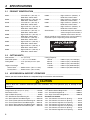
2.1 PRODUCT IDENTIFICATION_________________________________________________
62857.............................. Left Hand 18 in. (457 mm), 11
Blade Reel, without rollers.
62858.............................. Right Hand 18 in. (457 mm), 15
Blade Reel, without rollers.
62298.............................. Left Hand 18 in. (457 mm), 8
Blade Reel, without rollers.
62859.............................. Right Hand 18 in. (457 mm), 8
Blade Reel, without rollers.
62299.............................. Left Hand 18 in. (457 mm), 11
Blade Reel, without rollers.
62860.............................. Right Hand 18 in. (457 mm), 11
Blade Reel, without rollers.
62861.............................. Left Hand 22 in. (559 mm), 7
Blade Reel, without rollers.
62862.............................. Right Hand 22 in. (559 mm), 7
Blade Reel, without rollers.
62863.............................. Right Hand 22 in. (559 mm), 9
Blade Reel, without rollers.
62864.............................. Right Hand 22 in. (559 mm), 9
Blade Reel, without rollers.
62865.............................. Right Hand 22 in. (559 mm), 11
Blade Reel, without rollers.
62866.............................. Right Hand 22 in. (559 mm), 11
Blade Reel, without rollers.
62867.............................. Right Hand 22 in. (559 mm), 15
Blade Reel, without rollers.
62868.............................. Right Hand 22 in. (559 mm), 15
Blade Reel, without rollers.
Serial Number ................ An identification plate, like the one
shown, listing the serial number, is
attached to the frame of the reel.
Always provide the serial number of the unit when ordering
replacement parts or requesting service information.
2.2 CUTTING UNITS___________________________________________________________
Reel Diameter................. 5 in. (127 mm)
Reel Blade Options......... 7, 8, 9, 11, or 15 blades
Cutting Width .................. 18 in. (457 mm) or 22 in. (559
mm)
Height of Cut Range
Greens Reels............ 0.06 to 0.43 in. (1.6 to 11.1 mm)
Fairway Reels ........... 0.30 to 0.70 in. (7.6 to 18 mm)
Cutting Frequency
7 Blade ..................... 0.083 in./mph (1.314 mm/kph)
8 Blade ..................... 0.073 in./mph (1.150 mm/kph)
9 Blade ..................... 0.064 in./mph (1.010 mm/kph)
11 Blade ................... 0.053 in./mph (0.836 mm/kph)
15 Blade ................... 0.039 in./mph (0.613 mm/kph)
2.3 ACCESSORIES & SUPPORT LITERATURE ____________________________________
Contact your area Jacobsen Dealer for a complete listing of accessories and attachments.
Accessories
Orange Touch-up Paint (12 oz. spray) ......................554598
Rear Roller Cleaner .....................................................62820
High Cut Roller Kit (15/16”)..........................................68634
18 in. Reel Electric Drive Mounting Kit ....................4395138
18 in. Reel Hydraulic Drive Mounting Kit .................4395139
22 in. Fairway Reel Hydraulic Drive Mounting Kit....4395140
22 in. Fairway Reel Electric Drive Mounting Kit.......4395141
22 in. Greens Reel Hydraulic Drive Mounting Kit ....4395142
22 in. Greens Reel Electric Drive Mounting Kit........4395143
Magknife Kit
22 in. Medium Section Magknife Kit ........................ 4266571
22 in. Tournament Magknife Kit............................... 4266551
22 in. Super Tournament Magknife Kit.................... 4266570
Standard Turf Groomer
18 in. Turf Groomer Left Hand 1/4” Spacing ............... 67160
18 in. Turf Groomer Left Hand 1/2” Spacing ............... 67161
18 in. Turf Groomer Right Hand 1/2” Spacing............. 67162
22 in. Turf Groomer Left Hand 1/4” Spacing ............... 67163
22 in. Turf Groomer Right Hand 1/4” Spacing............. 67164
22 in. Turf Groomer Left Hand 1/2” Spacing ............... 67165
22 in. Turf Groomer Right Hand 1/2” Spacing............. 67166
CHARLOTTE, NC PRODUCT OF U.S.A.
®
A Textron Company
62857001651
CAUTION
Use of other than Jacobsen authorized parts and accessories may cause personal injury or damage to the
equipment.
!

SPECIFICATIONS 2
7
Bi-Directional Groomer/Brush
Left Hand Electric Drive .............................................. 62936
Right Hand Electric Drive............................................ 62937
Left Hand Hydraulic Drive ........................................... 62938
Right Hand Hydraulic Drive......................................... 62939
18 in. (457 mm) 1/4 in. Spacing Groomer Shaft ......... 62907
18 in. (457 mm) 1/2 in. Spacing Groomer Shaft ......... 62940
22 in. (559 mm) 1/4 in. Spacing Groomer Shaft ......... 62905
22 in. (559 mm) 1/2 in. Spacing Groomer Shaft ......... 62906
18 in. (457 mm) Stiff Bristle Herringbone Brush ......... 62915
18 in. (457 mm) Medium Bristle Herringbone Brush... 62916
18 in. (457 mm) Soft Bristle Herringbone Brush ......... 62917
22 in. (559 mm) Stiff Bristle Herringbone Brush ......... 62909
22 in. (559 mm) Medium Bristle Herringbone Brush... 62910
22 in. (559 mm) Soft Bristle Herringbone Brush ......... 62911
18 in. (457 mm) 1/4 in. Spacing Groomer Roller ........ 62930
18 in. (457 mm) 1/2 in. Spacing Groomer Roller ........ 62941
18 in. (457 mm) Smooth Roller ................................... 62931
22 in. (559 mm) 1/4 in. Spacing Groomer Roller ........ 62927
22 in. (559 mm) 1/2 in. Spacing Groomer Roller ........ 62928
22 in. (559 mm) Smooth Roller ................................... 62929
Quick Change Kit ........................................................ 62934
Guide Reel Kit............................................................. 62935
18 Inch (457 mm) Reel Rear Rollers
2 in. Full Width Hollow Tube w/ Scraper ................. 4420307
2 in. Narrow Width Solid Tube w/ Scraper .............. 4420310
2-3/16 in. Full Width Solid Tube w/ Scraper................ 68674
22 Inch (559 mm) Reel Rear Rollers
2 in. Narrow Width Solid Tube w/ Scraper .............. 4420310
2 in. Full Width Hollow Tube w/ Scraper ................. 4420313
2 in. Full Width Solid Tube w/ Scraper.................... 4420317
2-1/2 in. Narrow Width Hollow Tube ....................... 4420337
2-1/2 in. Full Width Hollow Tube ............................. 4420338
2-1/2 in. Wide Width Hollow Tube........................... 4420342
18 Inch (457 mm) Reel Front Rollers
2 in. Hollow Smooth Tube........................................4108920
2 in. Solid Smooth Tube with Scraper .........................68626
2-3/16 in. Machined Steel Grooved .............................68616
2-3/16 in. Machined Aluminum Grooved .....................63318
3 in. Assembled Disc with Scraper ..............................67925
22 Inch (559 mm) Reel Front Rollers
2 in. Hollow Smooth Tube with Scraper.......................68530
2 in. Solid Smooth Tube with Scraper .........................68641
2 in. Assembled Disc ...................................................68527
2-3/16 in. Machined Steel Grooved .............................68613
2-3/16 in. Machined Aluminum Grooved .....................68614
2-1/4 in. Segmented Machined....................................68673
3 in. Assembled Disc .................................................123268
Scraper for 123268 Roller..........................................391202
Support Literature
Technical Repair Manual.........................................4269792

2 SPECIFICATIONS
8
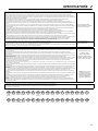
2.4 DECLARATION OF INCORPORATION_________________________________________
DECLARATION OF INCORPORATION ▪ ДЕКЛАРАЦИЯ ЗА ОБЕДИНЕНИЕ ▪ PROHLÁŠENÍ O ZALOŽENÍ SPOLEČNOSTI ▪ INKORPORERINGSERKLÆRING ▪
INCORPORATIEVERKLARING ▪ KINNITUS ÜHENDAMISE KOHTA ▪ ASENNUSTODISTUS ▪ DECLARATION D’INCORPORATION ▪ EINBAUBESCHEINIGUNG ▪ ∆ΗΛΩΣΗ ΜΗ
ΣΥΜΜΟΡΦΩΣΗΣ ▪ BEÉPÍTÉSI NYILATKOZAT ▪ DICHIARAZIONE DI INCORPORAZIONE ▪ NOFORMĒŠANAS DEKLARĀCIJA ▪ PRIJUNGIMO DEKLARACIJA ▪
DIKJARAZZJONI
TA’ INKORPORAZZJONI ▪ DEKLARACJA ZGODNOŚCI DLA PODZESPOŁU ▪ DECLARAÇÃO DE INCORPORAÇÃO ▪ DECLARAŢIE DE ÎNCORPORARE ▪ VYHLÁSENIE O
ZABUDOVANÍ SÚČASTI ▪ IZJAVA ZA VGRADNJO ▪ DECLARACIÓN DE INCORPORACIÓN ▪ INBYGGNADSDEKLARATION
Business name and full address of the manufacturer ▪ Търговско име и пълен адрес на производителя ▪ Obchodní jméno a plná adresa výrobce ▪
Producentens firmanavn og fulde adresse ▪ Bedrijfsnaam en volledig adres van de fabrikant ▪ Tootja ärinimi ja täielik aadress ▪
Valmistajan toiminimi ja täydellinen osoite ▪ Nom commercial et adresse complète du fabricant ▪ Firmenname und vollständige Adresse des Herstellers ▪
Επωνυμία και ταχυδρομική διεύθυνση κατασκευαστή ▪ A gyártó üzleti neve és teljes címe ▪ Ragione sociale e indirizzo completo del fabbricante ▪
Uzņēmuma nosaukums un pilna ražotāja adrese ▪ Verslo pavadinimas ir pilnas gamintojo adresas ▪ Isem kummerċjali u indirizz sħiħ tal-fabbrikant ▪
Nazwa firmy i pełny adres producenta ▪ Nome da empresa e endereço completo do fabricante ▪ Denumirea comercială şi adresa completă a producătorului ▪
Obchodný názov a úplná adresa výrobcu ▪ Naziv podjetja in polni naslov proizvajalca ▪ Nombre de la empresa y dirección completa del fabricante ▪
Tillverkarens företagsnamn och kompletta adress
Textron Specialty Vehicles
1452 Marvin Griffin Road
Augusta, GA 30906, USA
Description and identification of the partly completed machinery. ▪ Описание и идентификация на частично завършените машини. ▪ Popis a identifikace částečně dokončeného strojního zařízení. ▪
Beskrivelse og identifikation af den delvist fremstillede maskine. ▪ Beschrijving en identificatie van de gedeeltelijk voltooide machinerie. ▪ Osaliselt komplekteeritud masina kirjeldus ja määratlus. ▪
Osittain kootun laitteiston kuvaus ja määrittely. ▪ Description et identification de la quasi-machine. ▪ Bezeichnung und Identifizierung der teilgefertigten Vorrichtung ▪ Περιγραφή και προσδιορισμός ημιτελούς μηχανήματος. ▪
A részlegesen megépített gép leírása és meghatározása. ▪ Descrizione e identificazione della quasi-macchina ▪ Da ļēji pabeigtas iekārtas apraksts un identifikācija. ▪ Dalinai užbaigtos įrangos aprašymas ir identifikacija. ▪
Deskrizzjoni u identifikazzjoni tal-makkinarju li jkun lest parzjalment. ▪ Opis i oznaczenie częściowo ukończonego urządzenia ▪ Descriç ão e identificação do equipamento parcial ▪
Descrierea şi identificarea echipamentului finalizat parţial ▪ Opis a identifikácia podzostavy strojného zariadenia ▪ Opis in identifikacija delno dokončanega stroja. ▪ Descripción e identificación de la maquinaria parcialmente completada. ▪
Beskrivning och identifiering av maskindelarna.
Product Code Serial Number Description
62857 6285701651 ~ 6285702999 Left Hand 18 in. (457 mm) 11 Blade TrueSet
™
Reel
62858 6285801651 ~ 6285802999
Left Hand 18 in. (457 mm) 15 Blade TrueSet
™
Reel
62298 6229801651 ~ 6229802999
Left Hand 18 in. (457 mm) 8 Blade TrueSet
™
Reel
62859 6285901651 ~ 6285902999
Right Hand 18 in. (457 mm) 8 Blade TrueSet
™
Reel
62299 6229901651 ~ 6229902999
Left Hand 18 in. (457 mm) 11 Blade TrueSet
™
Reel
62860 6286001651 ~ 6286002999 Right Hand 18 in. (457 mm) 11 Blade TrueSet
™
Reel
62861 6286101651 ~ 6286102999
Left Hand 22 in. (559 mm) 7 Blade TrueSet
™
Reel
62862 6286201651 ~ 6286202999 Right Hand 22 in. (559 mm) 7 Blade TrueSet
™
Reel
62863 6286301651 ~ 6286302999
Left Hand 22 in. (559 mm) 9 Blade TrueSet
™
Reel
62864 6286401651 ~ 6286402999
Right Hand 22 in. (559 mm) 9 Blade TrueSet
™
Reel
62865 6286501651 ~ 6286502999
Left Hand 22 in. (559 mm) 11 Blade TrueSet
™
Reel
62866 6286601651 ~ 6286602999
Right Hand 22 in. (559 mm) 11 Blade TrueSet
™
Reel
62867 6286701651 ~ 6286702999 Left Hand 22 in. (559 mm) 15 Blade TrueSet
™
Reel
62868 6286801651 ~ 6286802999
Right Hand 22 in. (559 mm) 15 Blade TrueSet
™
Reel
We undertake to transmit, in response to a reasoned request by the national authorities, relevant information on the partly completed machinery. This shall be by hardcopy and shall be without prejudice to the intellectual property rights of the
manufacturer of the partly completed machinery.
Ние обещаваме да предадем, в отговор на основателно искане от националните органи, съответна информация за частично завършените машини. Това ще се осъществи чрез документ и няма да бъде в нарушение на правата за
интелектуална собственост на производителя на частично завършените машини.
Zavazujeme se na základě zdůvodněné žádosti ze strany národních úřadů poskytnout příslušné informace o částeč
ně dokončeném strojním zařízení. Informace budou předány v tištěné podobě a nepoškodí práva k duševnímu vlastnictví výrobce
týkající se částečně dokončeného strojního zařízení.
Som svar på en begrundet anmodning fra de nationale myndigheder forpligter vi os til at videregive oplysninger om den delvist fremstillede maskine. Dette bliver gjort i papirudgave og med forbehold for de immaterielle rettigheder, som indehaves af
producenten af den delvist fremstillede maskine.
We zijn van plan, in reactie op een redelijk verzoek van de nationale autoriteiten, relevante informatie over de gedeeltelijk voltooide machinerie te verzenden. Dit wordt gedaan in de vorm van fysieke kopieën en deze kopieën zullen onder alle
voorbehoud behoren tot de intellectuele eigendomsrechten van de fabrikant van de gedeeltelijk voltooide machinerie.
Me kohustume riigisiseste asutuste põhjendatud nõudmisel edastama asjakohast teavet osaliselt komplekteeritud masina kohta. Andmed edastatakse paberkandjal ning sellega ei tohi piirata osaliselt komplekteeritud masina tootja õigusi intellektuaalsele
omandile.
Sitoudumme toimittamaan osittain koottua laitteistoa koskevat olennaiset tiedot vastineena kansallisten viranomaisten perusteltuun pyyntöön. Tiedot toimitetaan paperitulosteena. Ne eivät rajoita valmistajan osittain koottua laitteistoa koskevia
immateriaalioikeuksia.
Nous nous engageons à fournir, en réponse à une demande rationnelle des autorités nationales, toute information appropriée concernant la quasi-machine. Ceci se fera par copie papier et sans préjuger des droits de propriété intellectuelle du fabricant
de la quasi-machine.
Wir verpflichten uns, auf eine begründete Aufforderung durch die nationalen Behörden hin, relevante Informationen über die teilgefertigte Maschine zu übersenden. Diese werden als Ausdruck übersandt und dürfen sich nicht nachteilig auf die Rechte
am geistigen Eigentum des Herstellers der teilgefertigten Maschine auswirken.
Αναλαμβάνουμε να μεταβιβάσουμε, προς απάντηση εύλογης αίτησης των εθνικών αρχών, τις σχετικές πληροφορίες όσον αφορά το ημιτελές μηχάνημα. Αυτό θα πρέπει να γίνει γραπτώς και δίχως να θίγει τα πνευματικά
δικαιώματα του κατασκευαστή
του ημιτελούς μηχανήματος.
Vállaljuk, hogy átadjuk – a nemzeti hatóságok megalapozott kérésére válaszul – a részlegesen megépített gépre vonatkozó információkat. Az információkat nyomtatott példányban adjuk át. A nyomtatott példány átadása a részlegesen megépített gép
gyártójának szellemi tulajdonjogaira tett kötelezettség nélkül történik.
Ci impegniamo a trasmettere, in risposta ad una richiesta adeguatamente motivata delle autorità nazionali, informazioni pertinenti sulla quasi-macchina. L’impegno sarà redatto in forma cartacea e lascerà impregiudicati i diritti di proprietà intellettuale del
fabbricante della quasi-macchina.
Atsaucoties uz pamatotu valsts iestāžu pieprasījumu, mēs apņemamies nodot saistīto informāciju par daļēji pabeigtu iekārtu. Tā būs cietā kopija un neradīs kaitējumus daļēji pabeigtās iekārtas ražotāja intelektuālā īpašuma tiesībām.
Atsakydami į nacionalinių valdžios organų užklausą, pateikiame informaciją apie dalinai užbaigtus mechanizmus. Šis dokumentas yra atspausdintas elektroninio originalo variantas ir be jokio išankstinio nusistatymo neturi tikslo pažeisti dalinai užbaigto
mechanizmo gamintojo intelektualinės nuosavybės teisių.
Aħna nwiegħdu li nippreżentaw, meta mitlubin mill-awtoritajiet nazzjonali, l-informazzjoni relevanti dwar il-makkinarju li jkun lest parzjalment. Din l-informazzjoni għandha tkun f’forma stampata u mingħajr preġudizzju għad-drittijiet tal-proprjetà intelletwali
tal-fabbrikant tal-makkinarju li jkun lest parzjalment.
Na uzasadnion
ą prośbę instytucji państwowych zobowiązujemy się do przekazania wszelkich informacji na temat częściowo ukończonego urządzenia. Będą one przekazane na piśmie. Strona przekazująca w/wym. dokumentację nie będzie rościła sobie
żadnych praw do własności intelektualnej producenta częściowo ukończonego urządzenia.
Na sequência de pedido razoável por parte das autoridades nacionais, comprometemo-nos a transmitir informações importantes sobre o equipamento parcial. Tal será feito por meio de hardcopy
e sem prejuízo para os direitos de propriedade intelectual do fabricante do equipamento parcial.
Ne angajăm să transmitem, ca răspuns la o solicitare motivată a autorităţilor naţionale, informaţii relevante privind echipamentul finalizat parţial. Aceasta se va efectua în format hârtie şi fără a aduce atingere drepturilor de proprietate intelectuală ale
producătorului echipamentului finalizat parţial.
Zaväzujeme sa, že na základe odôvodnenej požiadavky národných orgánov predložíme dôležité informácie o podzostave strojného zariadenia.
Musí to byť v tlačenej forme a bez ujmy na právach duševného vlastníctva výrobcu podzostavy strojného zariadenia.
Zavezujemo se, da bomo na utemeljeno zahtevo nacionalnih organov predložili zadevne informacije o delno dokončanem stroju. Informacije bodo v tiskani obliki in ne bodo posegale v pravice intelektualne lastnine proizvajalca delno dokončanega stroja.
Nos comprometemos a transmitir, en respuesta a una petición razonada por parte de las autoridades nacionales, información relevante sobre la maquinaria parcialmente completada. Ésta será transmitida en copia impresa y no afectará a los derechos
de propiedad intelectual del fabricante de la maquinaria parcialmente completada.
Vi åtar oss att vidarebefordra relevant information om maskindelarna vid en motiverad förfrågan från nationella myndigheter. Informationen ska erhållas i form av papperskopior och ska vara utan men för maskindelstillverkarens immateriella rättigheter.

SPECIFICATIONS 2
9
Partly completed machinery must not be put into service until the final machinery into which it is to be incorporated has been declared in conformity with the provisions of Directive 2006/42/EC.
Частично завършените машини не трябва да бъдат пускана в употреба, докато крайните машини, в които са вградени, не са приведени в съответствие с постановленията на директива 2006/
42/EО.
Částečně dokončené zařízení nesmí být uvedeno do provozu, dokud konečné zařízení, do kterého bylo uvedené zařízení namontováno, neodpovídá ustanovením Směrnice č. 2006/42/EC.
Delvist fremstillede maskiner må ikke indsættes i driften, før den endelige maskine, som den skal inkorporeres i, er blevet erklæret I overensstemmelse med bestemmelserne i Direktiv 2006/42/EF.
Gedeeltelijk voltooide machinerie mag niet in dienst worden genomen, totdat er voor de definitieve machinerie, waarvan gedeeltelijk voltooide machinerie onderdeel uitmaakt, een conformiteitsverklaring
is ontvangen onder de voorwaarden van Richtlijn 2006/42/EG.
Osaliselt komplekteeritud masinat ei tohi kasutusele võtta enne, kui lõplikult komplekteeritud masin, millega see ühendatakse, on tunnistatud direktiivi 2006/42/EÜ sätetele vastavaks.
Osittain koottua laitteistoa ei saa ottaa käyttöön, ennen kuin lopullinen laitteisto, johon se asennetaan, on vakuutettu direktiivin 2006/42/EY säännösten mukaiseksi.
La quasi-machine ne doit pas être mise en service avant que la machine finale dans laquelle elle doit être incorporée n’ait été déclarée conforme aux dispositions de la directive 2006/42/CE
Die teilgefertigte Vorrichtung darf erst in Betrieb genommen werden, wenn die Konformität der Maschine, in die sie eingebaut wird, entsprechend den Bestimmungen der Richtlinie 2006/42/EG erklärt
worden ist.
Θα πρέπει να εκτελεστεί σέρβις στο ημιτελές μηχάνημα μέχρι το τελικό μηχάνημα στο οποίο θα ενσωματωθεί να έχει τη δήλωση συμμόρφωσης, σύμφωνα με τις διατάξεις της Οδηγίας 2006/42/ΕΚ.
A részlegesen megépített gépet tilos üzembe helyezni mindaddig, amíg a 2006/42/EK irányelv rendelkezéseivel összhangban a részlegesen megépített gépet be nem építik a végleges változatba, és
erről nem nyilatkoznak.
La quasi-macchina non deve essere messa in servizio finché la macchina finale in cui deve essere incorporata non è stata dichiarata conforme, nel caso, alle disposizioni della Direttiva 2006/42/CE.
Daļēji pabeigtu iekārtu nedrīkst nodot ekspluatācijā, līdz galīgā iekārta, kurā tā ir jāiebūvē, ir deklarēta atbilstoši direktīvas Nr. 2006/42/EK noteikumiem.
Dalinai užbaigto mechanizmo negalima paleisti kol kiti mechanizmai, kurie dar bus prijungti, nebus patvirtinti kaip atitinkantys 2006/42/EC Direktyvos reikalavimus.
Il-makkinarju li jkun parzjalment lest ma g ħandux jibda jitħaddem sakemm il-makkinarju finali li fih ikun se ji ġi inkorporat ikun ġie ddikjarat konformi mad-dispożizzjonijiet tad-Direttiva 2006/42/KE.
Urządzenia częściowo ukończonego nie wolno użytkować aż do orzeczenia zgodności urządzenia w postaci kompletnej z wymaganiami dyrektywy 2006/42/WE.
O equipamento parcial não poderá entrar em funcionamento antes do mecanismo final no qual vai ser incorporado ser declarado como estando em conformidade com as condições da Directiva 2006/
42/CE.
Echipamentul finalizat parţial nu trebuie pus în funcţiune până ce echipamentul final în care va fi încorporat nu este declarat ca fiind conform cu prevederile Directivei 2006/42/CE.
Podzostava strojného zariadenia nesmie byť uvedená do prevádzky, pokiaľ finálne strojné zariadenie, ktorého sa stane súčasťou, nebude vyhlásené ako zhodné s ustanoveniami smernice 2006/42/ES.
Delno dokončanega stroja ni dovoljeno dati v obratovanje, dokler se dokončani stroj, v katerega se vgradi delno dokončani stroj, ne potrdi kot skladen z določbami Direktive 2006/42/ES.
La maquinaria parcialmente completada no debe ponerse en servicio hasta que la maquinaria final a la que debe incorporarse cumpla con las provisiones de la Directiva 2006/42/CE.
Maskindelarna får ej tas i bruk förrän maskinen som delen tillhör har deklarerats som överensstämmande med föreskrifterna I direktivet 2006/42/EG.
These accessories have been
designed to be fitted to the Jacobsen
127 mm (5 inch) reel mowers.
The place and date of the declaration ▪ Място и дата на декларацията ▪ Místo a datum prohlášení ▪ Sted og dato for erklæringen ▪
Plaats en datum van de verklaring ▪ Deklaratsiooni väljastamise koht ja kuupäev ▪ Vakuutuksen paikka ja päivämäärä ▪ Lieu et date de la déclaration ▪
Ort und Datum der Erklärung ▪ Τόπος και ημερομηνία δήλωσης ▪ A nyilatkozat kelte (hely és idő) ▪ Luogo e data della dichiarazione ▪
Deklarācijas vieta un datums ▪ Deklaracijos vieta ir data ▪ Il-post u d-data tad-dikjarazzjoni ▪ Miejsce i data wystawienia deklaracji ▪ Local e data da declaração ▪ Locul şi data declaraţiei ▪ Miesto a dátum
vyhlásenia ▪ Kraj in datum izjave ▪ Lugar y fecha de la declaración ▪ Plats och datum för deklarationen
Textron Specialty Vehicles
1452 Marvin Griffin Road
Augusta, GA 30906, USA
TBD
Signature of the person empowered to draw up the declaration on behalf of the manufacturer, holds the technical documentation and is authorised to compile the technical file, and who is established in
the Community.
Подпис на човека, упълномощен да състави декларацията от името на производителя, който поддържащ техническата документация и е оторизиран да изготви техническия файл и е
регистриран в общността.
Podpis osoby oprávněné sestavit prohlášení jménem výrobce, držet technickou dokumentaci a osoby oprávněné sestavit technické soubory a založené v rámci Evropského společenství.
Underskrift af personen, der har fuldmagt til at udarbejde erklæringen på vegne af producenten, der er indehaver af dokumentationen og er bemyndiget til at udarbejde den tekniske journal, og som er
baseret i nærområdet.
Handtekening van de persoon die bevoegd is de verklaring namens de fabrikant te tekenen, de technische documentatie bewaart en bevoegd is om het technische bestand samen te stellen, en die is
gevestigd in het Woongebied.
Ühenduse registrisse kantud isiku allkiri, kes on volitatud tootja nimel deklaratsiooni koostama, kes omab tehnilist dokumentatsiooni ja kellel on õigus koostada tehniline toimik.
Sen henkilön allekirjoitus, jolla on valmistajan valtuutus vakuutuksen laadintaan, jolla on hallussaan tekniset asiakirjat, joka on valtuutettu laatimaan tekniset asiakirjat ja joka on sijoittautunut yhteisöön.
Signature de la personne habilitée à rédiger la déclaration au nom du fabricant, à détenir la documentation technique, à compiler les fichiers techniques et qui est implantée dans la Communauté.
Unterschrift der Person, die berechtigt ist, die Erklärung im Namen des Herstellers abzugeben, die die technischen Unterlagen aufbewahrt und berechtigt ist, die technischen Unterlagen
zusammenzustellen, und die in der Gemeinschaft niedergelassen ist.
Υπογραφή ατόμου εξουσιοδοτημένου για την σύνταξη της δήλωσης εκ μέρους του κατασκευαστή, ο οποίος κατέχει την τεχνική έκθεση και έχει την εξουσιοδότηση να ταξινομήσει τον τεχνικό φάκελο και
ο οποίος είναι διορισμένος στην Κοινότητα.
A gyártó nevében meghatalmazott személy, akinek jogában áll módosítania a nyilatkozatot, a műszaki dokumentációt őrzi, engedéllyel rendelkezik a műszaki fájl összeállításához, és aki a közösségben
letelepedett személy.
Firma della persona autorizzata a redigere la dichiarazione a nome del fabbricante, in possesso Della documentazione tecnica ed autorizzata a costituire il fascicolo tecnico, che deve essere stabilita
nella Comunità.
Tās personas paraksts, kura ir pilnvarota deklarācijas sastādīšanai ražotāja vārdā, kurai ir tehniskā dokumentācija, kura ir pilnvarota sagatavot tehnisko reģistru un kura ir apstiprināta Kopienā.
Asmuo, kuris yra gana žinomas, kuriam gamintojas suteikė įgaliojimus sudaryti šią deklaraciją, ir kuris ją pasirašė, turi visą techninę informaciją ir yra įgaliotas sudaryti techninės informacijos dokumentą.
Il-firma tal-persuna awtorizzata li tfassal id-dikjarazzjoni f’isem il-fabbrikant, għandha d-dokumentazzjoni teknika u hija awtorizzata li tikkompila l-fajl tekniku u li hija stabbilita fil-Komunità.
Podpis osoby upoważnionej do sporządzenia deklaracji w imieniu producenta, przechowującej dokumentację techniczną, upoważnioną do stworzenia dokumentacji technicznej oraz wyznaczonej ds.
wspólnotowych.
Assinatura da pessoa com poderes para emitir a declaração em nome do fabricante, que possui a documentação técnica, que está autorizada a compilar o processo técnico e que está estabelecida na
Comunidade.
Semnătura persoanei împuternicite să elaboreze declaraţia în numele producătorului, care deţine documentaţia tehnică, este autorizată să compileze dosarul tehnic şi este stabilită în Comunitate.
Podpis osoby poverenej vystavením vyhlásenia v mene výrobcu, ktorá má technickú dokumentáciu a je oprávnená spracovať technické podklady a ktorá je umiestnená v Spoločenstve.
Podpis osebe, pooblaščene za izdelavo izjave v imenu proizvajalca, ki ima tehnično dokumentacijo in lahko sestavlja spis tehnične dokumentacije, ter ima sedež v Skupnosti.
Firma de la persona responsable de la declaración en nombre del fabricante, que posee la documentación técnica y está autorizada para recopilar el archivo técnico y que está establecido en la
Comunidad.
Undertecknas av den som bemyndigad att upprätta deklarationen å tillverkarens vägnar, innehar den tekniska dokumentationen och är bemyndigad att sammanställa den tekniska informationen och
som är etablerad i gemenskapen.
2006/42/EC Annex II 1.A.2
Christian D. Clifford
Director of Engineering
Ransomes Jacobsen Limited
West Road, Ransomes Europark,
Ipswich, IP3 9TT, England
2006/42/EC Annex II 1.A.10
Christopher W. Spencer
Vice President of Engineering
Textron Specialty Vehicles
1452 Marvin Griffin Road
Augusta, GA 30906, USA
Certificate Number ▪ Номер на сертификат ▪ Číslo osvědčení ▪ Certifikatnummer ▪ Certificaatnummer ▪ Sertifikaadi number ▪ Hyväksyntänumero ▪
Numéro de certificat ▪ Bescheinigungsnummer ▪ Αριθμός Πιστοποιητικού ▪ Hitelesítési szám ▪ Numero del certificato ▪ Sertifikāta numurs ▪
Sertifikato numeris ▪ Numru taċ-Ċertifikat ▪ Numer certyfikatu ▪ Número do Certificado ▪ Număr certificat ▪ Číslo osvedčenia ▪ Številka certifikata ▪
Número de certificado ▪ Certifikatsnummer
4387946-DOI Rev A
GB
United
Kingdom
BE
Belgium
BG
Bulgaria
CH
Switzerland
CN
China
CY
Cyprus
CZ
Czech
Republic
DE
Germany
DK
Denmark
EE
Estonia
ES
Spain
FI
Finland
FR
France
GR
Greece
HU
Hungary
IS
Iceland
IT
Italy
JP
Japan
KR
Korea
LI
Liechenstein
LT
Lithuania
LV
Latvia
MT
Malta
NL
Netherlands
NO
Norway
PL
Poland
PT
Portugal
RO
Romania
RU
Russia
SE
Sweden
SI
Slovenia
SK
Slovakia
TR
Turkey
UA
Ukrain

3 SETUP
10
3 SETUP
3.1 GENERAL INFORMATION __________________________________________________
1. A mounting kit is required to install the reel onto your
mower and must be ordered separately. Check with
your dealer for the correct mounting kit for your
mower.
a. Callouts identified with a single letter, (A) through
(G), are part of the mower. Refer to the mower’s
manual for part numbers.
b. Callout with double letters, (AA) are part of the
reel. Refer to the parts list in this manual for parts
identification.
c. Callouts with triple letters, (AAA) through (ABF),
are parts of the reel mounting kit. Refer to the
parts list in this manual for parts identification.
2. If installed, remove existing reels from the mower,
using instructions in the mower’s manuals. Separate
lift yoke from the reels.
3. The front and rear rollers are not included with the
reel assembly and must be ordered separately.
Check with your dealer for rollers that are available
for your mower. Follow installation instructions
included with the rollers.
4. Figures show assembly of a left hand fairway reel.
Greens reels similar. Right hand reels are opposite.
3.2 REEL ACCESSORIES ______________________________________________________
Other accessories may also be available for your reel
such as Turf Groomer®, roller scrapers, and roller
brushes. Install these accessories before installing reels.
Follow instructions included in your mower’s manuals
and/or Turf Groomer’s Instruction Sheet for adjusting the
reel to bedknife and height of cut.
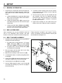
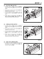
3.3 REEL TO MOWER ASSEMBLY_______________________________________________
1. Assemble the lift yoke (A) to the reel using hardware
included in the reel mounting kit.
a. For fairway reels, use two 3/8-16 x 1-1/4” screws
(AAA), lockwasher (AAB), flat washer (AAC)
and spacers (AAD) to assemble the lift yoke (A).
b. For greens reels, use two shoulder bolts (AAE)
to assemble the lift yoke (A).
2. Start the engine and fully lower the lift arms. Stop
the engine and remove the key.
3. Move the reel assembly in front of the lift arm (B).
4. If included with mower, assemble spring (F) onto the
lift yoke (A).
5. Lift the lift arm (B) and move the reel so that the lift
yoke (A) is aligned with the swivel housing (C).
6. Carefully lower lift arm (B) onto lift yoke (A).
7. Install pin (D) through the hole in the lift yoke (A)
and fasten the retaining clip. Install the cap (E) on
the swivel housing.
Figure 3A
B
C
A
F
D
E
AAA
AAA
AAB
AAB
AAC
AAC
AAD
AAE
AAE
AAD

SETUP 3
11
3.4 ELECTRIC REEL MOTOR ___________________________________________________
1. Assemble motor pins (AAF) and lock nuts (AAG) to
motor bearing housing (AA) using mounting holes
shown.
2. Apply grease to splines of reel coupler (AAH) and
assemble to end of reel shaft.
3. Slide motor (G) onto motor pins (AAF). Adjust reel
to align spline of coupler (AAH) to motor shaft
spline.
4. Secure motor by inserting motor clips (AAJ) into
slots in motor pins (AAF). Loops of motor clips
should face toward the center of the motor.
Figure 3B
3.5 HYDRAULIC REEL MOTOR__________________________________________________
1. Assemble motor pins (AAF) and lock nuts (AAG) to
motor bearing housing (AA) using mounting holes
shown.
2. Apply grease to splines of reel coupler (AAH) and
assemble to end of reel shaft.
3. Slide motor (G) onto motor pins (AAF). Adjust reel
to align spline of coupler (AAH) to motor shaft
spline.
4. Secure motor by inserting motor clips (AAJ) into
slots in motor pins (AAF). Loops of motor clips
should face toward the center of the motor.
Figure 3C
3.6 REEL STOP (GREENS REEL) ________________________________________________
1. Assemble reel mower stop (AAL) to the reel using
two 5/16-18 x 3/4” hex head screws (AAK) and
spiralock flange nuts (AAM).
Figure 3D
AAJ
AAF
Electric
Motor Holes
AAF
AAG
AA
AAH
G
AAJ
AAF
AAF
AAG
AA
AAH
G
Hydraulic
Motor Hole
s
AAK
AAL
AAM

3 SETUP
12
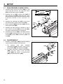
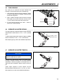
3.7 DOWN PRESSURE (FAIRWAY REEL) _________________________________________
1. Assemble down pressure bracket (AAN) to reel
frame using two 5/16-18 x 3/4” hex head screws
(AAK) and spiralock flange nuts (AAM).
2. Assemble jam nut (AAP) and ball joint (AAR) to
down pressure rod (AAS). Adjust ball joint so the
distance between center of ball joint hole and center
of rod hole is 8-15/16 ± 1/16 in. (227 mm ± 1.5
mm).
3. Assemble the adjustment pin (AAT) to the fourth
hole from ball joint in down pressure rod (AAS).
4. Slide flat washer (ABG) and spring (AAU) onto the
down pressure rod (AAS).
5. Assemble the down pressure assembly to the lift
yoke. Press the rod pin (AAV) into the rod (AAS).
The rod pin must be horizontal to the ground.
6. Assemble the ball joint (AAR) to the down pressure
bracket (AAN) using one 3/8-16 x 1-3/4” hex head
screw (AAW), spacer (AAX), lockwasher (AAY) and
nut (AAZ).
Figure 3E
3.8 COUNTERWEIGHT ________________________________________________________
1. Assemble counterweight (ABA) to bearing housing
using hardware included in the mounting kit.
a. For hydraulic drive reels, assemble
counterweight (ABA) using two 1/4-20 x 7/8 hex
head screws (ABB) and lockwashers (ABC).
b. For electric drive reels, assemble counterweight
(ABD) using one 1/4-20 x 3-1/4” hex head
screws (ABE), one 1/4-20 x 1” hex head screw
(ABF) and two lockwashers (ABC).
Figure 3F
AAK
8-15/16 in.
(227 mm)
AAM
ABG
AAN
AAP
AAR
AAS
AAT
AAU
AAV
AAW
AAX
AAY
AAZ
ABA
ABB
ABC
ABC
ABC
ABC
ABD
ABE
ABF

ADJUSTMENTS 4
13
4 ADJUSTMENTS
4.1 GENERAL ________________________________________________________________
1. Adjustments and maintenance should always be
performed by a qualified technician. If proper
adjustment cannot be made, contact an authorized
Jacobsen Dealer.
2. Replace, do not adjust, worn or damaged
components.
3. Long hair, jewelry or loose fitting clothing may get
tangled in moving parts.
4. Do not change speed limit settings or overspeed the
drive motors.
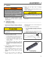
4.2 BEDKNIFE-TO-REEL _______________________________________________________
(Pre-adjustment Check)
1. Check the reel bearings for end play or radial play.
There should be no end play or radial play. See Section
4.10.
2. Inspect the reel blades and bedknife to insure good
sharp edges without bends or nicks.
a. The leading edge of the reel blades must be sharp,
free of burrs and show no signs of rounding off.
b. The bedknife and bedknife backing must be
securely tightened. The bedknife must be
straight and sharp.
c. A flat surface of at least 1/32 in. (0.8 mm)
minimum must be maintained on the front face of
the bedknife. Use a standard flat file to dress the
bedknife.
3. If wear or damage is beyond the point where the reel
or bedknife can be corrected by the lapping process,
they must be reground.
4. Proper reel-to-bedknife adjustment is critical. A gap of
0.001 to 0.003” (0.025 to 0.076 mm) must be
maintained across the entire length of the reel and
bedknife.
5. The reel must be parallel to the bedknife. An
improperly adjusted reel will lose its sharp edges
prematurely and may result in serious damage to the
reel and bedknife.
6. Grass conditions will also affect the adjustment.
a. Dry, sparse conditions will require a wider gap to
prevent heat buildup and damage to the reel and
bedknife.
b. High quality grass with a good moisture content
requires a closer gap (near zero).
Figure 4A
Figure 4B
WARNING
Before you clean, adjust, or repair this equipment,
disengage all drives, lower implements to the ground,
turn system power off, remove key from ignition switch,
and disconnect battery pack(s) to prevent injuries
Make sure the mower is parked on a solid and level
surface. Never work on a mower that is supported only
by the jack. Always use jack stands.
!
CAUTION
Be careful to prevent entrapment of the hands and
fingers between moving and fixed components of the
machine.
!
CAUTION
To prevent personal injury and damage to the cutting
edges, wear gloves and handle the reel and bedknife
with extreme care.
!
°
°
1/32”
(0.8 mm)
Leading Edge

4 ADJUSTMENTS
14
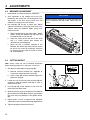
4.3 BEDKNIFE ADJUSTMENT __________________________________________________
1. Read Section 4.1 before making the adjustment.
2. Start adjustment at the leading end of the reel,
followed by the trailing end. The leading end of the
reel blades is that end which passes over the
bedknife first during normal reel rotation.
3. Use adjusters (B and C), to adjust gap. Rotate
adjusters (Clockwise) to close gap. Each click of the
adjuster moves the bedknife 0.001” (0.025 mm)
closer to the reel.
a. Slide a feeler gauge or shim stock 0.001” - 0.003”
(0.025 - 0.075 mm) between the reel blade and
the bedknife. Do not turn the reel.
b. Adjust the trailing end of the reel to the same
gap in a similar manner then recheck the
adjustment at the leading end.
c. When the reel is properly adjusted to the
bedknife, the reel will spin freely and you should
be able to cut a piece of newspaper, along the
full length of the reel, when the paper is held at
90° to the bedknife.
Figure 4C
4.4 CUTTING HEIGHT _________________________________________________________
Note: Always make the reel to bedknife adjustment
before adjusting height of cut. (Sections 4.2 and 4.3).
1. Set desired cutting height on the gauge (E).
a. Measure distance between the underside of
screw head and gauge block surface (F).
b. Adjust screw (H) to obtain desired height then
tighten the wing nut.
2. Loosen the nuts on the front roller brackets (G) just
enough to allow the adjuster knob (K) to raise or
lower the front roller.
3. Place gauge (E) across bottom of front and rear
rollers near one end of roller.
4. Slide the head of gauge screw (H) over the bedknife
(L) and adjust the knob (K) to close the gap between
the screw head and bedknife. Then tighten locknut
(G).
5. Repeat Steps 4 and 5 on opposite end. Complete
adjustment to one end before adjusting opposite end.
6. Tighten nuts (G) and recheck each end.
Figure 4D
NOTICE
Avoid excessive tightening or serious damage may
result to bedknife and reel blades. Reels must turn
freely.
B
C
F
K
G
E
H
J

ADJUSTMENTS 4
15
4.5 REEL BEARING ___________________________________________________________
Any radial play or excessive end play indicates bad
bearings, a weak tension spring or a backed off nut.
1. Check bearing housing mounting hardware. Tighten
or replace components as required. Carefully clean
threads with degreaser.
2. Apply a medium strength grade of Loctite to nut (P),
then thread nut onto the reel shaft until the nut is
1-27/32” (46 mm) from the end of the reel shaft.
3. Fill reel bearing housings with NLGI - Grade O
grease after adjusting spring.
Figure 4E
4.6 BEDKNIFE ADJUSTER SPRING ______________________________________________
For proper operation, bedknife adjuster spring should be
compressed to a dimension of 1-7/16 - 1-1/2 in. (36.5-38
mm).
To adjust spring compression, loosen or tighten nut (R) to
obtain a distance of 1-7/16 - 1-1/2 in. (36.5-38 mm).
After adjusting spring, check reel to bedknife adjustment.
Figure 4F
4.7 BEDKNIFE ADJUSTER TENSION _____________________________________________
Remove hair pin (U) and fully loosen, then tighten slotted
nut (S) to remove clearance (no end play) between
components. Continue to tighten nut until next slot in nut
aligns with hole in bedknife adjuster rod (T). Install hair
pin.
Check torque required to rotate adjuster rod (T).
Maximum torque should be 24 in. lb. (2 ft. lb.) (2.7 Nm).
After adjusting nut, check reel to bedknife adjustment.
Figure 4G
GKV-11
1-27/32 in.
(46 mm)
P
P
R
T
1-7/16 to 1-1/2 in.
(3.65 to 3.8 cm)
NOTICE
Overtightening slotted nut (S) will make bedknife
adjuster rod (T) difficult to adjust.
U
V
W
X
S
T

4 ADJUSTMENTS
16
4.8 GRINDING BEDKNIFE ______________________________________________________
Bedknife can be lowered out of the reel for grinding
without completly removing the bedknife assembly.
1. Remove cotter pin (U), slotted nut (S), bellville
washer (V), shim washer (W-If required), and half
trunnion (X). See Figure 4G
4. Press down on adjuster end of rod (T) to rotate other
end of the adjuster out of the bedknife finger.
5. Rotate bedknife backing to access the reel and
bedknife for grinding.
6. After grinding, assemble bedknife using reverse
order of removal. Check adjustment of bedknife
adjuster tension (Section 4.7), and reel to bedknife
adjustment (Section 4.3).
4.9 DOWN PRESSURE SPRING _________________________________________________
Each fairway reel is has a down pressure spring. Down
pressure improves the cutting quality by contact between
the reel and ground. Check and adjust the down pressure
any time the HOC is changed or to improve the cut for the
best performance.
1. Lift the reels to the transport position. Put the
adjustment pin in 4th hole from ball joint. Lower the
reels onto a flat surface before you measure the
down pressure.
2. Set the distance between the ball joint center and
the rod pin center to 8-15/16 in. ± 1/16 in. (22.7 mm
± 0.2 cm). To adjust the length, loosen the jam nut
and rotate the rod into or out of the ball joint.
3. Measure length of spring as shown on all 5 reels.
Record the shortest spring dimension. Adjust the
ball joint to get the other springs to the same
dimension ± 1/16 in. (0.2 cm). The rod pin must be
horizontal, then tighten the jam nut.
4. To adjust the down pressure, move the adjustment
pin one hole toward the spring to increase the down
pressure on the rear roller. Move the adjustment pin
one hole away from the spring to decrease the
down pressure on the rear roller.
Figure 4H
Ball
Joint
Jam
Nut
Adjustment
Pin
8-15/16 in.
(22.7 cm)
Rod
Pin
Rod

ADJUSTMENTS 4
17
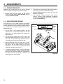
4.10 TORQUE SPECIFICATION___________________________________________________
Jacobsen uses Grade 5 Plated bolts as standard, unless otherwise noted. For tightening plated bolts, use the value
given for lubricated.
NOTICE
All torque values included in these charts are approximate and are for reference only. Use of these torque values is
at your sole risk. Jacobsen is not responsible for any loss, claim, or damage arising from the use of these charts.
Extreme caution should always be used when using any torque value.
AMERICAN NATIONAL STANDARD FASTENERS
SIZE UNITS GRADE 5 GRADE 8 SIZE UNITS GRADE 5 GRADE 8
Lubricated Dry Lubricated Dry Lubri-
cated
Dry Lubri-
cated
Dry
#6-32 in-lb (Nm) – 20 (2.3) – – 7/16-14 ft-lb (Nm) 37 (50.1) 50 (67.8) 53 (71.8) 70 (94.9)
#8-32 in-lb (Nm) – 24 (2.7) – 30 (3.4) 7/16-20 ft-lb (Nm) 42 (56.9) 55 (74.6) 59 (80.0) 78 (105)
#10-24 in-lb (Nm) – 35 (4.0) – 45 (5.1) 1/2-13 ft-lb (Nm) 57 (77.2) 75 (101) 80 (108) 107 (145)
#10-32 in-lb (Nm) – 40 (4.5) – 50 (5.7) 1/2-20 ft-lb (Nm) 64 (86.7) 85 (115) 90 (122) 120 (162)
#12-24 in-lb (Nm) – 50 (5.7) – 65 (7.3) 9/16-12 ft-lb (Nm) 82 (111) 109 (148) 115 (156) 154 (209)
1/4-20 in-lb (Nm) 75 (8.4) 100 (11.3) 107 (12.1) 143 (16.1) 9/16-18 ft-lb (Nm) 92 (124) 122 (165) 129 (174) 172 (233)
1/4-28 in-lb (Nm) 85 (9.6) 115 (13.0) 120 (13.5) 163 (18.4) 5/8-11 ft-lb (Nm) 113 (153) 151 (204) 159 (215) 211 (286)
5/16-18 in-lb (Nm) 157 (17.7) 210 (23.7) 220 (24.8) 305 (34.4) 5/8-18 ft-lb (Nm) 128 (173) 170 (230) 180 (244) 240 (325)
5/16-24 in-lb (Nm) 173 (19.5) 230 (26.0) 245 (27.6) 325 (36.7) 3/4-10 ft-lb (Nm) 200 (271) 266 (360) 282 (382) 376 (509)
3/8-16 ft-lb (Nm) 23 (31.1) 31 (42.0) 32 (43.3) 44 (59.6) 3/4-16 ft-lb (Nm) 223 (302) 298 404 315 (427) 420 (569)
3/8-24 ft-lb (Nm) 26 (35.2) 35 (47.4) 37 (50.1) 50 (67.8) 7/8-14 ft-lb (Nm) 355 (481) 473 (641) 500 (678) 668 (905)
METRIC FASTENERS
SIZE UNITS
Non Critical
Fasteners
into
Aluminum
Lubricated Dry Lubricated Dry Lubricated Dry Lubricated Dry
M4 Nm (in-lb)––––––3.83 (34)5.11 (45)2.0 (18)
M5 Nm (in-lb) 1.80 (16) 2.40 (21) 4.63 (41) 6.18 (54) 6.63 (59) 8.84 (78) 7.75 (68) 10.3 (910 4.0 (35)
M6 Nm (in-lb) 3.05 (27) 4.07 (36) 7.87 (69) 10.5 (93) 11.3 (102) 15.0 (133) 13.2 (117) 17.6 (156) 6.8 (60)
M8 Nm (in-lb) 7.41 (65) 9.98 (88) 19.1 (69) 25.5 (226) 27.3 (241) 36.5 (323) 32.0 (283) 42.6 (377) 17.0 (150)
M10 Nm (ft-lb) 14.7 (11) 19.6 (14) 37.8 (29) 50.5 (37) 54.1 (40) 72.2 (53) 63.3 (46) 84.4 (62) 33.9 (25)
M12 Nm (ft-lb) 25.6 (19) 34.1 (25) 66.0 (48) 88.0 (65) 94.5 (70) 125 (92) 110 (81) 147 (108) 61.0 (45)
M14 Nm (ft-lb) 40.8 (30) 54.3 (40) 105 (77) 140 (103) 150 (110) 200 (147) 175 (129) 234 (172) 94.9 (70)
4.6
8.8
10.9
12.9

18
1
2
2
8
8
9
9
10
10
11
11
11
11
12
13
14
14
15
15
15
16
16
17
17
18
19
20
21
4
5
5
6
6
6
7
7
3
3
4127335
4181860
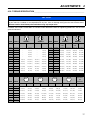
TRUESET™ REEL
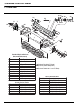
6.1 Outer Reel
Serial No. All

19
> Change from previous revision
TRUESET™ REEL
Item Part No. Qty. Description Serial Numbers/Notes
1
REF 1 Inner Reel See 7.1
2 1002224 2 Zerk Bolt
3 365246 2 Shoulder Bolt
4 2810043 1 Shield, Grass
5 4181860 1 Decal, Read Manual for Service
6 4127335 2 Decal, Danger
7 352737 2 Set Screw, 1/4-20 x 7/8” Grade 8
8 403782 2 Screw, 1/4-20 x 3/4” Truss Head
9 453023 2 Flat Washer, 1/4
10 446130 2 Lockwasher, 1/4 Heavy
11 443102 4 Nut, 1/4-20 Hex
12 3008438 1 Bracket, Right Side Front Roller
13 3008439 1 Bracket, Left Side Front Roller
14 441674 2 Carriage Bolt, 5/16-18 x 1-3/4”
15 445795 4 Nut, 5/16-18 Spiralock Flange
16 343616 2 Stud, Front Roller Adjuster
17 3005692 2 Knob, Front Roller Adjuster
18 367164 1 Spacer
19 453011 1 Flat Washer, 3/8
20 446142 1 Lockwasher, 3/8 Heavy
21 400294 1 Screw, 3/8-24 x 1” Hex Head

20
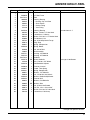
18 Inch Service Reels
22 Inch Service Reels
Part Number Description
4119512 18” RH 8 Blade Reel
4170220 18” LH 11 Blade Reel
4119513 18” RH 11 Blade Reel
Part Number Description
5001100 22” RH 9 Blade Reel
5001101 22” LH 11 Blade Reel
4391646 18” LH 8 Blade Reel
5001099 22” LH 9 Blade Reel
5003054 22” RH 7 Blade Reel
5003053 22” LH 7 Blade Reel
5001102 22” RH 11 Blade Reel
4225504 18” LH 15 Blade Reel
4225505 22” LH 15 Blade Reel
4269791 22” RH 15 Blade Reel
1
2
3
4
4
5
5
6
7
6
7
8
11
11
12
13
13
14
15
17
18
20
21
22
23
24
24
25
26
27
28
35
36
29
30
31
32
33
34
19
16
10
9
16
10
9
Standard Style Bedknives
(Secured with screws)
Part Number Description
5000098 18” Low Profile
■ 4118902 18” Medium Section
● 5002888 18” Super Tournament
4234901 18” Championship
◆ 503478 22” Low Profile
503477 22” High Profile
503460 22” Heavy Section
503479 22” To urnament
4234900 22” Championship
▲ 5003150 22” Medium Section
● 5002887 22” Super Tournament
▲ Standard Bedknife (7 Blade)
■ Standard Bedknife (8 Blade)
◆ Standard Bedknife (9 Blade)
● Standard Bedknife (11 and 15 Blade)
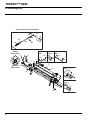
GREENS KING IV REEL
7.1 Inner Reel
Serial No. All
Pagina se încarcă...
Pagina se încarcă...
Pagina se încarcă...
Pagina se încarcă...
-
 1
1
-
 2
2
-
 3
3
-
 4
4
-
 5
5
-
 6
6
-
 7
7
-
 8
8
-
 9
9
-
 10
10
-
 11
11
-
 12
12
-
 13
13
-
 14
14
-
 15
15
-
 16
16
-
 17
17
-
 18
18
-
 19
19
-
 20
20
-
 21
21
-
 22
22
-
 23
23
-
 24
24


Ransomes 62298 62299 62857 62858 62859 62860 62861 62862 62863 62864 62865 62866 62867 62868 Accessories Manual
- Tip
- Accessories Manual
în alte limbi
Lucrări înrudite
Alte documente
-
Hendi 222140 Manual de utilizare
-
Smithco Spray Star 2004 SN200G188 – 200G277 Manualul proprietarului
-
-
 Wellis Clarice push button Manual de utilizare
-
-
-
-
-
-
Kermi ZB04730001 Mounting instructions
