Smithco 7576 Tournament Ultra Lite Roller Manualul proprietarului
- Tip
- Manualul proprietarului


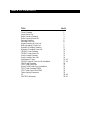
TABLE OF CONTENTS
TITLE PAGE
Frame Drawing 1
Frame Parts List 2
Roller Housing Drawing 3
Roller Housing Parts List 4
Steering Drawing 5
Steering Parts List 6
Engine Drawing & Parts List 7
Wiring Drawing & Parts List 8
Hydraulic Plumbing Drawing 9
Hydraulic Plumbing Parts List 10
750-847 Pump Drawing 11
750-847 Pump Parts List 12
Pump Linkage Drawing 13
Pump Linkage Parts List 14
Performance Chart 15-16
750-555 Light Kit Parts List & Installation 17-19
7520 Trailer Drawing 20
7520 Trailer Parts List 21
Guide Rail & Roller Stop Installation 22
7525 Trailer Drawing f/7000 23
7525 Trailer Parts List f/7000 24
Trailer Spring Placement 25
CE 26-28
SMITHCO Warranty 29-30

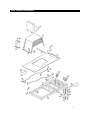
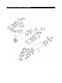
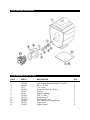
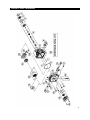
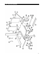
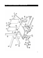
7576 FRAME DRAWING
1

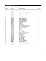
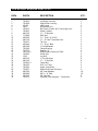
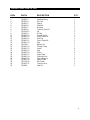
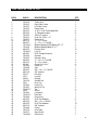
7576 FRAME PARTS LIST
REF# PART# DESCRIPTION QTY.
1 832-123-2 Low-Back “Smithco” Seat Assembly 1
2 750-913 Engine Cover 1
3 750-917 Engine Cover Hold Down 4 7/8” 2
4 750-891 Gas Shock Assembly w/Ball Stud 1
5 750-911 Seat Hinge 1
6 750-916 Oil Tank 1
7 750-908 Deck Plate 1
8 720-078-1 5/16” x 1” Clevis Pin 2
9 720-079 Cotter Pin 3/32” x ¾” 2
10 11-101-1 ¼” Fine Thread Yoke 2
11 750-915 Left Foot Pedal Rod 1
12 750-914 Right Foot Pedal Rod 1
14 750-912 Foot Pedal 2
15 10-007 Bushing 4
16 750-906 Main Frame 1
17 750-192 1 1/8” Poly Hex Nut & Cap 2
18 932-042 Thick Slotted Hex Nut 1 ¼” – 12 2
19 709-143-1 1/8” x 2 ½” Cotter Pin 2
20 932-023 Bearing 4
21 932-024 Spacer 2
22 932-022 Seal 4
23 400-061 ½” x 3 1/2” Bolt 1
24 750-186 Spacer ½” ID x ¾” OD x ½” 2
25 750-907 Swivel Axle Bracket 1
26 750-118-1 Oil Tank Cap 1
27 400-112 ½” Lock Nut 1
28 400-008 5/16” x 2 ½” Bolt 2
29 400-109 5/16” Lock Nut 2
30 400-116 3/8” Lock Nut 2
31 400-018 3/8” x 2 ½” Bolt 2
32 44-967 5/16” FT Tie Rod End 2
33 400-002 5/16” x 1” HHCS 2
34 400-281 5/16” Flange Locknut 2
35 750-942 Left Outer Step (CE Only) 1
36 750-943 Right Outer Step (CE Only) 1
37 750-269 Battery Box 1
2

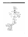
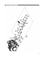
7576 ROLLER HOUSING DRAWING
3

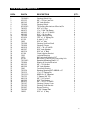
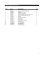
7576 ROLLER HOUSING PARTS LIST
REF# PART# DESCRIPTION QTY.
1 750-825 Left Roller Housing 1
2 750-826 Right Roller Housing 1
4 40-199 Idler Spring 1
5 1083 #50 Master Link 3
6 750-415 #50 Chain 50 pitch w/3 Connecting Links 1
7 750-821 Roller Cylinder 2
8 400-105 ½” – 13 Hex Nut 5
9 713-806 Ball Joint 2
10 400-056 ½” – 13 X 2 ½” HHCS 2
11 400-136 ½” – 20 Fine Thread Hex Nut 2
12 750-411 Tie Rod 1
13 400-044 ¼” – 20 x 1” Bolt 2
14 400-208 ¼” Lock Washer 2
15 720-004 Flange Bearing 2
16 750-721 Spacer 1 ¼” 2
17 750-220-2 Hub w/Plate, Bushing & Shaft 2
21 750-802 Hub 4 Bolt 2
22 1189 Lug Bolt 8
23 400-210 ½” Lock Washer 8
24 400-105 ½” – 13 Hex Nut 8
25 750-801-3 Castle Nut 2
26 740-023 3/16” x ¾” Key 2
27 750-801 Hydro Gear Motor 2
28 750-827 Bolted End Plate f/Housing 2
29 400-209 3/8” Lock Washer 16
30 400-090 3/8” x 1 ¼” Bolt 16
31 400-103 3/8” Hex Nut 8
32 750-873 Steering Chain Adjuster – Turnbuckle 1
4

7576 STEERING DRAWING
5

7576 STEERING PARTS LIST
REF# PART# DESCRIPTION QTY.
1 730-046-2 Steering Wheel Cap 1
2 932-122 5/8” – 18 Hex Jam Nut 1
3 400-143 5/8” Lock Washer 1
4 730-046 Steering Wheel 1
5 832-028-1 Tilt Steering Mechanism & Boot w/Pin 1
6 740-023 3/16” x ¾” Key 1
7 400-073 ¼” x 1” Self Tap Screw 4
8 400-003 5/16” – 18 x 1 ¼” HHCS 4
9 400-102 5/16” – 18 Hex Nut 8
10 750-286 Upper Steering Shaft 1
11 832-030 7/32” x 1 ¼” Spring Pin 1
12 41-120 U-Joint ¾” x ¾” 1
13 1088 3/16” x 1” Key 3
14 750-266 Steering Sprocket Shaft 1
15 750-909 Steering Column 1
16 400-010 5/16” – 18 x 5” HHCS 2
17 400-207 5/16” Lock Washer 8
18 400-314 5/16” x 4 ¼” Bolt 2
19 41-194 Chain Adjuster Bracket 1
20 1036 Jackshaft Bearing 2
21 1075 #40 Jackshaft Sprocket 11T 1
22 41-251 #40 Chain x 108 Pitch w/Connecting Link 1
23 750-148-1 Sprocket & Bearing Shaft 5 ½” 1
24 750-894 Bearing & Sprocket Bracket 1
25 400-103 3/8” – 16 Hex Nut 4
26 400-209 3/8” Lock Washer 4
27 1040 Front Axle Bearing 1
28 750-234 Steering Sprocket 60T 40BS60 x ¾” 1
29 750-315 ¼” x 2 ½” Spring Pin 2
30 750-133-1 50BS 19 x ¾” Sprocket 1
31 750-722 1” Spacer (3/4” ID) 1
32 400-116 3/8” – 16 Locknut 4
33 400-202 5/16” Flat Washer 4
34 400-015 3/8” – 16 x 1 ½” HHCS 4
35 750-107 Steering Column Cover 1
36 750-195 Steering Shaft Bracket 1
37 520-007 Bronze Bushing 2
38 709-382 ¼” 90° Grease Zert 1
39 1088-1 3/16” x 1 ½” Key 1
6

7576 ENGINE DRAWING
7576 ENGINE PARTS LIST
REF# PART# DESCRIPTION QTY.
1 750-935 8 HP Engine (Model# GX240UT2 -QAR2) 1
2 400-090 3/8” x 1 ¼” Bolt 8
3 1517 ¼” x 1” Key 1
4 750-851 Pump Hub 17mm w / #5 Key 1
5 720-027 Element 1
6 41-147 Engine Coupling 1” 1
7 750-201 3/16” x 1” Key 1
8 750-127 Bell Housing 6” 1
9 750-127-1 Bell Housing Cover 1
10 750-847 16cc without Aux Charge Pump 1
11 750-211 Engine Base 1
12 750-927 Engine Spacer 4
7

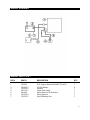
WIRING DRAWING
WIRING PARTS LIST
REF# PART# DESCRIPTION QTY.
1 750-935 8 HP Engine (Model# GX240UT2-QAR2) 1
2 750-555-7 PS1230 Battery 1
3 750-555-5 Rectifier 1
4 932-119-1 Safety Seat Switch 1
5 942-049 Wiring Harness f/Seat Switch 1
6 750-555-6 Wiring Harness 1
7 750-555-2 Light Kit Battery Box 1
8

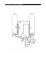
HYDRAULIC PLUMBING DRAWING
9

HYDRAULIC PLUMBING PARTS LIST
REF# PART# DESCRIPTION QTY.
1 750-916 Oil Tank 1
2 750-825 Left Roller Housing 1
3 750-826 Right Roller Housing 1
4 750-302 Filter Head 1
5 750-801 Wheel Motor 2
6 750-847 16cc without Aug Charge Pump 1
7 750-326 Wheel Motor Fitting 4
8 750-325 Oil Filter Head Fitting 2
9 750-322 Pump Fitting 2
10 750-324 Pump Fitting Top 1
11 750-295 Pump Fitting 1
12 750-920-1 Hyd Hose 57” x ½” (w/o 90° to Straight) 1
13 750-502 Hard Line Clamp 2
14 750-920-2 Hydraulic Hose 14” – Pump to Filter 1
15 750-920-3 Hydraulic Hose 35” 2
16 750-920-4 Hydraulic Hose 11” – Oil Tank to Filter Head 1
17 750-920-5 Hydraulic Hose 7” – Oil Tank to Pump 1
18 750-519 Hard Line Long Left Side 1
19 750-520 Hard Line Short Left Side 1
20 750-506 Hard Line Long Right Side 1
21 750-507 Hard Line Short Right Side 1
22 750-923 Drain Cap 1
23 750-920-6 Drain Hose 1
24 750-920-7 Hydraulic Hose 52” 1
25 750-118-2 Oil Tank Cap w/Dipstick 1
NOTE: OIL FILTER IS A PART# 750-300
COMPLETE HOSE KIT IS A PART# 750-920
10

750-847 PUMP DRAWING
11

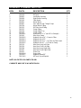
750-847 PUMP PARTS LIST
REF# PART# DESCRIPTION QTY.
1 750-847-3 Retaining Ring 1
2 750-847-4 Lip Seal 1
3 750-847-5 Spacer 1
4 750-847-6 Shaft Kit 1
5 750-847-7 Housing 1
6 750-847-8 Trunnion Seal Kit 1
7 750-228-15 Pin 2
8 750-847-9 O-Ring 1
9 750-847-10 Charge Relief 1
10 750-847-11 Shock Valve Kit 1
11 750-847-12 End Cap 1
12 750-847-11 Shock Valve Kit 1
13 750-847-13 Plug 1
14 750-228-7 Bypass Kit 1
15 750-847-14 Charge Pump 1
16 750-847-15 Screw 4
17 750-847-13 Plug 1
18 750-847-16 Screw 2
19 750-847-17 Valve Plate 1
20 750-847-18 Cylinder Block 1
21 750-847-19 Thrust Bearing 1
22 750-847-20 Swash Plate 1
23 750-128-38 Slot Guide 1
24 750-847-21 Trunnion Arm 1
25 750-849 Seal Kit 1
12

PUMP LINKAGE DRAWING
13

PUMP LINKAGE PARTS LIST
REF.# PART# DESCRIPTION QTY.
1 750-847 16cc without Aug Charge Pump 1
2 750-228-30 Bushing 1
3 750-343-1 Shift Lever Top (New) 1
3 750-343 Shift Lever Top (Old) 1
4 750-344-1 Shift Lever Bottom w/Bolt (Sq. Hole .470) 1
4 750-344 Shift Lever Bottom (Sq. Hole .350) 1
5 750-228-31 Bushing 1
6 750-345 Shift lever Right (Bent) 1
7 750-229-1 Gold Spring 1
8 750-228-32 Nylon Washer 1
9 750-346 Shift Lever Left (Straight) 1
10 750-228-33 Nylon Washer 1
11 750-228-34 5/16” Flat Washer 2
12 750-228-35 Allen Head Bolt 1
13 750-228-36 Allen Head Bolt 1
14 750-228-37 Pump Bracket Kit 1
14

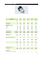
PERFORMANCE CHART
Product Type
PC
PG
PJ
PR
PW
Displacement
in
3
/rev
[cc/rev]
0.37
[6.1]
0.62
[10.2]
0.73
[12]
0.97
[16]
1.33
[21.8]
Input Speed
Maximum Unloaded
Minimum Loaded
rpm
rpm
3600
1800
3600
1800
3600
1800
3600
1800
3600
1800
System Operating Pressure
Continuous
Intermittent
Peak
psi
[bar]
psi
[bar]
psi
[bar]
750
[51]
1750
[120]
2500
[172]
1000
[70]
2100
[145]
3500
[240]
1000
[70]
2100
[145]
3500
[240]
1250
[86]
2500
[172]
3750
[260]
1250
[86]
2500
[172]
3750
[260]
Pump Performance
@ 2400 rpm/1000 psi
@ 3000 rpm/1000 psi
@ 3600 rpm/1000 psi
gpm [l/min]
gpm [l/min]
gpm [l/min]
3.6 [13.6]
4.5 [17.0]
5.4 [20.4]
6.1 [23.1]
7.6 [28.8]
9.2 [34.8]
7.1 [26.8]
8.9 [33.6]
10.8 [40.8]
9.6 [36.3]
12 [45.4]
14.4 [54.5]
13.1 [49.6]
16.4 [62.1]
19.6 [74.2]
Case Pressure
Maximum @ Cold Start
Continuous - Max.
psi [bar]
psi [bar]
10 [0.7]
4 [0.3]
10 [0.7]
4 [0.3]
10 [0.7]
4 [0.3]
25 [1.7]
10 [0.7]
25 [1.7]
10 [0.7]
Inlet Vacuum
Maximum Continuous Inches Mercury
4
4
4
4
4
Charge Pump Displacement(s)
in
3
/rev
[cc/rev]
.13
[2.1]
0.11/0.13
[1.9/2.1]
0.19
[3.2]
0.13/0.19
[2.1/3.2]
0.13/0.19
[2.1/3.2]
Auxiliary Pump Displacement
in
3
/rev
[cc/rev]
0.19
[3.2]
0.19
[3.2]
0.19
[3.2]
0.19
[3.2]
0.19
[3.2]
Auxiliary Pump Relief Setting
psi
[bar]
650
[45]
650
[45]
650
[45]
650
[45]
650
[45]
Auxiliary Pump Performance
@3200 rpm, 500 psi, 70 SUS
[13 Cst] oil, & 180°F
gpm
[l/min]
1.8 - 2.0
[6.8 - 7.6]
1.8 - 2.0
[6.8 - 7.6]
1.8 - 2.0
[6.8 - 7.6]
1.8 - 2.0
[6.8 - 7.6]
1.8 - 2.0
[6.8 - 7.6]
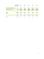
Control Torque Required
to Stroke Pump
[Approximate - 20° External Stroke Angle]
75
85
85
95
105
15

lb-in / 1000 psi
[N-m / 70 bar]
lb-in / 500 psi
[N-m / 35 bar]
[8.5]
55
[6.2]
[9.6]
60
[6.8]
[9.6]
60
[6.8]
[10.7]
75
[8.5]
[11.9]
85
[9.6]
Pump Oil Temperature
Maximum Intermittent (hottest point)
Normal Operating Range
°F
[°C]
°F
[°C]
230
[110]
-10 to 200
[-23 to 93]
230
[110]
-10 to 200
[-23 to 93]
230
[110]
-10 to 200
[-23 to 93]
230
[110]
-10 to 200
[-23 to 93]
230
[110]
-10 to 200
[-23 to 93]
Fluid Viscosity Limits @ 230°F [110°C]
Optimum
Minimum
SUS[cSt]
SUS[cSt]
70 [13]
55 [9]
70 [13]
55 [9]
70 [13]
55 [9]
70 [13]
55 [9]
70 [13]
55 [9]
Weight of Unit
lbs [kg]
7 [3.2]
8 [3.6]
12.65 [5.7]
12 [5.4]
14 [6.3]
Inlet Filtration Requirement
Nominal
micron
25
25
25
25
25
16

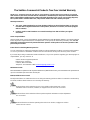
750-555 LIGHT KIT (Optional Accessory)
PART# DESCRIPTION QTY.
750-341-4 Switch Tab 1
750-555-4 Light Mount Bracket 1
750-555-8 Wiring Harness 1
750-555-1 Light Bulbs 2
W132 Loom Clamps 2
Zip Ties 4
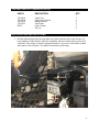
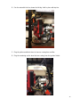
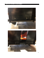
INSTALLATION INSTRUCTIONS
1. Bolt the light bracket under the seat plate using the front bolts on the seat. Use the (2)
loom clamps to hold the wires under the seat plate, which are held in place by the front
seat bolts. If the engine cover has expanded metal on it, you can cut out where needed
with a pair of side cut pliers. This allows the bracket to go through.
(Unit with Expanded Metal) (Unit without Expanded Metal)
17

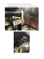
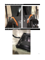
2. Bolt the lights onto the light bracket. Place switch tab on the left light.
3. Connect the wiring harness to the lights, with switch on the left side of machine. Run
wire through loom clamps.
18
Pagina se încarcă ...
Pagina se încarcă ...
Pagina se încarcă ...
Pagina se încarcă ...
Pagina se încarcă ...
Pagina se încarcă ...
Pagina se încarcă ...
Pagina se încarcă ...
Pagina se încarcă ...
Pagina se încarcă ...
Pagina se încarcă ...
Pagina se încarcă ...
Pagina se încarcă ...
-
 1
1
-
 2
2
-
 3
3
-
 4
4
-
 5
5
-
 6
6
-
 7
7
-
 8
8
-
 9
9
-
 10
10
-
 11
11
-
 12
12
-
 13
13
-
 14
14
-
 15
15
-
 16
16
-
 17
17
-
 18
18
-
 19
19
-
 20
20
-
 21
21
-
 22
22
-
 23
23
-
 24
24
-
 25
25
-
 26
26
-
 27
27
-
 28
28
-
 29
29
-
 30
30
-
 31
31
-
 32
32
-
 33
33


Smithco 7576 Tournament Ultra Lite Roller Manualul proprietarului
- Tip
- Manualul proprietarului
în alte limbi
Lucrări conexe
Alte documente
-
EINHELL TE-MG 300 EQ Kit Manual de utilizare
-
Ransomes HF600 Manualul proprietarului
-
Ransomes USAG004 / USAD004 / 62706 Manualul proprietarului
-
Billy Goat PL2501SPV Manualul proprietarului
-
-
-
-
Hitachi CS51EAP Handling Instructions Manual