
Spray Star 3180
3182 Radion 8140
3184 TeeJet 744
3185/3186 DynaJet/Aeros
3187/3188 DynaJet/Radion 8140
SN: 300G600
June 2020
Product Support: Hwy SS & Poplar Ave; Cameron WI 54822
1-800-891-9435 productsupport@smithco.com
Operator’s

Introduction
Operation Diagrams
Reference
CONTENTS
Introduction .................................................................. 1-8
Introduction ................................................................. 1
Symbols ...................................................................... 2
General Safety ......................................................... 3-6
Specications ............................................................. 7
Optional Spray Equipment .......................................... 7
Set Up ......................................................................... 8
Operation .................................................................... 9-15
Controls & Instruments ........................................... 9-10
Operation ..............................................................11-12
Tank Agitation ............................................................ 13
Sprayer Cleaning ...................................................... 14
Diagrams ................................................................... 15-17
Main Wiring Diagram ................................................. 15
Engine Wiring Diagram ............................................. 16
Hydraulic Diagram ..................................................... 17
Reference .................................................................. 18-21
Declaration of Conformity ..................................... 18-19
Quick Reference ....................................................... 20
Warranty ........................................................................

1
Introduction
PARTS MANUALS AVAILABLE ONLINE AT smithco.com
INTRODUCTION
Thank you for purchasing a Smithco product.
Read this manual and all other manuals pertaining to the Spray Star 3180 carefully as they contain safety,
operating, assembly and maintenance instructions. Failure to do so could result in personal injury or equip-
ment damage. Use in conjunction with appropriate TeeJet Manuals.
Keep manuals in a safe place after operator and maintenance personnel have read them. Right and left sides
are from the operator’s seat, facing forward.
All Smithco machines have a Serial Number and Model Number. Both numbers are needed when ordering
parts. The serial number plate on the Spray Star 3180 is located on top of the frame, between the hydro pump
and spray tank. Refer to engine manual for placement of engine serial number.
For product and accessory information, help nding a dealer, or to register your product please contact us at
www.Smithco.com.
Information needed when ordering replacement parts:
1. Model Number of machine
2. Serial Number of machine
3. Name and Part Number of part
4. Quantity of parts
For easy access record your Serial and Model numbers here.
Failure to follow cautious operating practices can
result in serious injury to the operator or other per-
sons. The owner must understand these instructions,
and must allow only trained persons who understand
these instructions to operate this vehicle.
WARNING
WARNING:
Engine exhaust and some of its constituents are
known to the State of California to cause cancer,
birth defects, and other reproductive harm.
For more information visit
www.P65Warning.ca.gov

2
Introduction
PARTS MANUALS AVAILABLE ONLINE AT smithco.com
SYMBOLS
Read Operator’s
Manual
Engine Stop
Engine Start
Engine Run
Engine Oil
Water
Temperature
RPM
Gasoline
Diesel
Glow Plug
Hour Meter Hand Throttle
Choke
Hydraulic
Oil Level
Ground Speed
Park Brake
Park Brake
Release
Fast
Slow
Lift Arm
Moving Parts
Pinch Point
Hot Surface
Hydraulic Fluid
Penetration
No Riders
Rollover
Danger
Headlamp
Blower
Warning
Danger
Caution
Seat Belt
20° MAX

3
Introduction
PARTS MANUALS AVAILABLE ONLINE AT smithco.com
SAFETY
Read and understand this manual and all safety signs before operating and maintaining. Review the safety
instructions and precautions annually.
TAKE NOTE! THIS SAFETY ALERT SYMBOL FOUND THROUGHOUT THIS MANUAL IS USED TO CALL
YOUR ATTENTION TO INSTRUCTIONS INVOLVING YOUR PERSONAL SAFETY AND THE SAFETY OF
OTHERS. FAILURE TO FOLLOW THESE INSTRUCTIONS CAN RESULT IN INJURY OR DEATH.
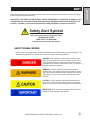
Safety Alert Symbol
This symbol with a warning statement means:
WARNING! BE ALERT!
YOUR SAFETY IS INVOLVED!
Carefully read the message that follows
SAFETY SIGNAL WORDS
Note the use of the signal words DANGER, WARNING and CAUTION with the safety messages. The
appropriate signal word for each has been selected using the following guidelines:
DANGER: Red. Indicates an imminently hazardous situa-
tion that, if not avoided, will result in death or serious injury.
This signal word is to be limited to the most extreme situa-
tions typically for machine components which, for functional
purposes, cannot be guarded.
WARNING: Orange. Indicates a potentially hazardous
situation that, if not avoided, could result in death or serious
injury, and includes hazards that are exposed when guards
are removed. It may also be used to alert against unsafe
practices.
CAUTION: Yellow. Indicates a potentially hazardous situ-
ation that, if not avoided, may result in minor or moderate
injury. It may also be used to alert against unsafe practices.
IMPORTANT: Blue. Indicates procedures which should be
followed to avoid damage to the machine.

4
Introduction
PARTS MANUALS AVAILABLE ONLINE AT smithco.com
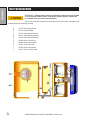
SAFETY DECAL LOCATION
REMEMBER: If Safety Decals have been damaged, removed, become illegible
or parts replaced without decals, new decals must be applied. New decals
are available from your authorized distributor.
This is a list of decals located on the Spray Star 3180. Part number, description and
location will help in reordering a decals.
A 15-463 Decal Spray Pump
B 25-370 Decal, 88 dBA
C 15-719 Decal, Speed Control
D 25-277 Decal, Battery Warning
E 25-279 Decal, Safety Warning
F 25-286 Decal, Pinch Point
G 25-298 Decal, Warning Hot
H 25-307 Decal, Fuel Only
I 32-619 Decal, Dash Panel
J 30-357 Decal, Control Panel

5
Introduction
PARTS MANUALS AVAILABLE ONLINE AT smithco.com
SAFE PRACTICES
1. It is your responsibility to read this manual and all publications associated with this machine.
2. Never allow anyone to operate or service the machine or its optional equipment without proper training
and instructions. Never allow minors to operate any equipment.
3. Learn the proper use of the machine, the location and purpose of all the controls and gages before you
operate the equipment. Working with unfamiliar equipment can lead to accidents.
4. Wear all the necessary protective clothing and personal safety devises to protect your head, eyes, ears,
hands and feet. Operate the machine only in daylight or in good articial light.
5. Inspect the area where the equipment will be used. Pick up all debris you can nd before operating.
Beware of overhead obstructions and underground obstacles. Stay alert for hidden hazards.
6. Never operate equipment that is not in perfect working order or without decals, guards, shields, or other
protective devices in place.
7. Never disconnect or bypass any switch.
8. Carbon monoxide in the exhaust fumes can be fatal when inhaled, never operate a machine without
proper ventilation.
9. Fuel is highly ammable, handle with care. When lling tank stop 1 inch(2.54 cm) from top. Leave room
for expansion. DO NOT OVERFILL.
10. Keep engine clean. Allow the engine to cool before storing and always remove the ignition key.
11. Disengage all drives and set park brake before starting the engine.
12. Never use your hands to search for oil leaks. Hydraulic uid under pressure can penetrate the skin and
cause serious injury.
13. This machine demands your attention. To prevent loss of control or tipping of the vehicle:
A. Use extra caution in backing up the vehicle. Ensure area is clear.
B. Do not stop or start suddenly on any slope.
C. Reduce speed on slopes and in sharp turns. Use caution when changing directions on slopes.
D. Stay alert for holes in the terrain and other hidden hazards.
14. Before leaving operator’s position:
A. Disengage all drives.
B. Shut engine o and remove the ignition key.
C. If engine has to run to perform any maintenance keep hands, feet, clothing and all other parts of
body away from moving parts.
15. Keep hands, feet and clothing away from moving parts. Wait for all movement to stop before you clean,
adjust or service the machine.
16. Keep the area of operation clear of all bystanders.
17. Stop engine before making repairs/adjustments or checking/adding oil to the crankcase.
18. Use parts and materials supplied by Smithco only. Do not modify any function or part.
19. Use caution when booms are down as they extend out beyond the center line of the machine.
20. The spray tank is a conned space, take precaution.
These machines are intended for professional maintenance on golf courses, sports turf, and any other
area maintained turf and related trails, paths and lots. No guaranty as to the suitability for any task is
expressed or implied.

6
Introduction
PARTS MANUALS AVAILABLE ONLINE AT smithco.com
SAFE SPRAYING PRACTICES
Persons engaged in the handling, preparation or application of chemicals must follow accepted practices to
insure the safety of themselves and others,
1. WEAR protective clothing including: gloves, hat, respirator, eye protection and skin covering suitable for
protection from chemicals being used.
2. BATHE thoroughly after any exposure to chemicals, giving particular attention to eyes, nose, ears and
mouth.
3. CLEAN equipment and materials in accordance with employer, municipal and state regulations. Use
only approved areas and drains.
4. DISPOSE of chemicals and rinse solutions by approved and legal means.
5. PROVIDE methods and materials for operators to wash eyes and hands immediately during the spray-
ing process.
6. PROVIDE methods and materials for control, safe dilution and neutralization of chemical spills during
preparation, spraying, transporting and cleanup.
7. Always check and follow the directions and safety warnings of the chemicals to be used.
8. Secure the discharge lines before starting the pump. An unsecured discharge line may whip.
9. Periodically inspect the pump and the system components.
10. Check hoses for weak or worn condition before each use. Make certain that all connections are tight
and secure.
11. Do not operate unit with leaks, frayed, kinked hoses or tubing. Repair or replace immediately.
12. Use only pipe, hose and ttings rated for maximum pressure or pressure at which pressure relief valve
is set at. When replacing pipe, hose or ttings, use new product.
13. Do not operate an engine in an enclosed area. Be sure the area is well ventilated.
14. Do not use these pumps for pumping water or other liquids for human or animal consumption.
15. Do not pump ammable or explosive uids such as gasoline, fuel oil,
kerosene, etc.
Do not use in explosive atmospheres. The pump should be used
only with liquids compatible with the pump component materials.
16. Be sure all exposed moving parts are guarded and that all coupling devices are securely attached be-
fore applying power.
17. Before servicing, disconnect all power, make sure all pressure in the system is relieved, drain all liquids
from the system and ush.
18. Protect pump from freezing conditions by draining liquid and pumping rust inhibiting antifreeze solution
through the system, coating the pump interior.
19. TRANSPORT - Machine must be stopped to raise or lower booms. Because of cam system, if booms
are raised in transit they can fall forward or backward when coming to a stop or while traveling on un-
even terrain.
20. If using Simulated Speed with a Radion 8140, one needs to change back
to Ground Speed for proper rate control when spraying.

7
Introduction
PARTS MANUALS AVAILABLE ONLINE AT smithco.com
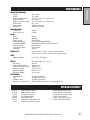
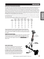
SPECIFICATIONS
WEIGHTS AND DIMENSIONS
Length 128" (3.3m)
Width 72" (1.8m)
Width w/ Booms Open 20' - 260" (6.6m) 18' - 240" (6.1m)
Height w/ ROPS 84" (2.1m)
Height w/ Booms Folded 20' - 136" (3.5m) 18' - 110"(2.8m)
Wheel Base 68" (1.7m)
Weight Empty 2340 lbs (1061 kg)
Weight Full 4950 lbs (2245 kg)
SOUND LEVEL (DBA)
At ear level 88 dBA
At 30 ft. (9.14 m) 77 dBA
ENGINE
Make Kubota
Model# WG1605
Code / Spec# G-E3-KEA-3
Rated Horsepower 57 hp (42.5kW) @3600RPM
Fuel (EMISSIONS) Unleaded 87 Octane Gasoline Minimum
Cooling System Liquid Cooled
Lubrication System Full Pressure
Alternator 40 Amp
WHEELS & TIRE Front: Two 20 x 11.00 x 10 Turf; 20 psi (1.4 bar)
Rear: Two 29 x 14.00 x 15 Multi-Trac; 30 psi (2.0 bar)
SPEED
Innitely Variable 0-10 m.p.h. (0-18 kph)
BATTERY Automotive type 24F - 12 volt
BCI Group Size 24
Cold Cranking Amps 900 minimum
Ground Terminal Polarity Negative (-)
Maximum Length 10.25" (26 cm)
Maximum Width 6.88" (17 cm)
Maximum Height 10" (25 cm)
FLUID CAPACITY
Crankcase Oil See Engine Manual
Fuel 20 gallon (75.7 liters)
Hydraulic Fluid 10 gallon (37.8 liters)
Grade of Hydraulic Fluid SAE 10W-40 API Service SJ or higher Motor Oil
OPTIONAL EQUIPMENT
15-618 Water Meter Kit (liters) 30-009 Manual Hose Reel
14-515 Water Meter Kit (Gal) 30-010 Electric Hose Reel
17-585 18' HD Super Boom 30-350 26 Gallon Wash Tank
17-580 20' HD Super Boom 30-375 Foam Marker
30-006 Fresh Water Tank 15-835 Tank Rinse System
30-007 Chemical Cleanload Safe Fill 15-850 Sunshade Canopy
17-622 Drift Reduction Boom Shield

8
Introduction
PARTS MANUALS AVAILABLE ONLINE AT smithco.com
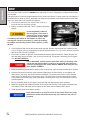
SETUP
The Spray Star 3180 arrives from Smithco setup and ready for service. Depending on freight conditions bat-
tery installed.
The spray system is normally shipped attached to the 3180 Prime Mover. If a spray system is to be tted to a
Prime Mover by a dealer or factory, assemble and attach the components in accordance with the parts draw-
ings in the Spray Star 3180 Parts/Service Manual.
1. Check the tire pressure. The front tires are 20 psi (1.4
bar) and rear tires are 30 psi (2.0 bar).
2. Battery is located under seat. This is a negative grounding
system.
Connecting battery cables to
the wrong post could result in
personal injury and/or damage
to the electrical system. Make
sure battery and cables do not interfere or rub on any
moving part. Connect red positive (+) cable (A) to battery
rst. When disconnecting remove black negative (-) cable
(B) rst.
3. Check hydraulic uid level in tank located under the seat. Remove cap and add SAE 10W-40 API Ser-
vice SJ or higher motor oil if necessary. Fluid level should be about 2-2
1
/
2
" (5-6.4 cm) from the top of the
tank when cold. DO NOT OVERFILL.
4. Fill fuel tank, located on right side, with Unleaded 87 Octane Gasoline Minimum. When lling the fuel
tank stop when the fuel reaches 1 inch (2.54cm) from the top. This space is necessary for fuel expan-
sion. DO NOT OVERFILL.
Fuel is ammable, caution must be used when storing or handling it. Do
not ll fuel tank while engine is running or an enclosed area, fumes are
explosive and dangerous to inhale. DO NOT SMOKE while lling the fuel
tank. DO NOT OVERFILL
5. Machine should be greased before starting, refer to Spray Star 3180 Parts/Service Manual for location.
6. Attach the Spray Boom and any other Optional Equipment to the Prime Mover, in accordance with
instructions in the Spray Star 3180 Parts/Service Manual. The nozzles must be the correct distance
above the turf as described in Turf Spraying Guide. The spray boom must operate properly and the
outer sections must break away safely if an object is struck by them, they must then return to normal
operation position.
7. Be sure to double check boom heights, nozzle spacing and displacement before spraying.
8. Machine is shipped with windshield washer uid in to prevent freezing. Flush system completely with
clear water. Fill tank with water and re-tighten the four bolts used to hold the tank in place.
9. Read operating instructions before starting.
Never allow pump to run dry! The valve on the suction side of the pump
(between the pump and tank) must be fully open whenever the pump is
operated.

9
Operation
PARTS MANUALS AVAILABLE ONLINE AT smithco.com
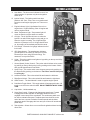
CONTROLS & INSTRUMENTS
A. Hour Meter - The hour meter indicates hours of ma-
chine operation. It operates only when the ignition
switch is on.
B. Ignition Switch - The ignition switch has three
positions: O - Run - Start. Turn to run position and
leave there until engine light goes out. Then turn to
start.
C. Engine Indicator Light- Light ashes if there is an
engine issue. If light is ashing. Shut o engine and
refer to engine manual.
D. Water Temperature Light - Temperature light will
come on when the engine starts to overheat.
E. Oil Light - The oil light should come on when the
ignition is on without the engine running and go out
when the engine is running. The oil light will light
when the oil pressure is low. If oil light should come
on, shut engine o immediately and nd the cause.
F. Fuel Gauge - Electronic fuel gauge indicates level of
fuel in tank.
G. GPS Speedometer - The speedometer indicates
ground speed of the vehicle in miles per hour and
kilometers per hour using GPS technology. The
antenna is on top of the ROPs.
H. Lights - This rocker switch turns lights on by pushing on the top and o by
pushing on the bottom.
I. Ground Speed (Cruise) Control - This rocker switch initiates cruise control
by pushing on the top and turning it o by pushing on the bottom. Works
with ground Speed Control Foot switch.
J. Spray Pump - This rocker switch turns the spray pump on by pushing on
the top and o by pushing on the bottom. The buzzer sounds if the pump
is running dry.
K. Left Boom Switch - This rocker switch lifts and lowers the left boom.
L. Right Boom Switch - This rocker switch lifts and lowers the right boom.
M. Hand Throttle - The hand throttle is used to regulate engine speed.
N. Park Brake Toggle Switch - This toggle switch will engage park brake. Lift
toggle cover and move switch forward. DO NOT ENGAGE WHILE IN MO-
TION.
O. Cup Holder - Holds standard cup.
P. Spray Boss Control - Engages and disengages speed boss. Forward
is engage and all the way back is disengage. When the lever is
engaged it sets a stop for the accelerator. The accelerator pedal must
be used to maintain this speed. To adjust speed use the knob on the
end of the lever, counter clockwise increases speed and clockwise
decreases speed. Disengage the lever and you will have full accelerator
pedal range.
Q. Tank Agitation - Allows driver to turn on/o tank agitation without leaving
driver seat.

10
Operation
PARTS MANUALS AVAILABLE ONLINE AT smithco.com
CONTROLS & INSTRUMENTS
R. Ground Speed (Cruise) Control Foot Switch - When rocker
switch is turned on and desired speed is obtained, push
foot speed control switch to set cruise. (See below).
S. Master Boom Switch - located on the left oorboard is
used to override the master switch on the computer con-
sole of the spray systems. By pushing down it will turn on/
o the booms. For TeeJet Systems, the master switch on
the computer must be on.
T. Accelerator Pedal - This pedal controls ground speed.
Press pedal to increase speed. Varying the amount of
movement of the pedal will vary the ground speed.
U. Reverse Pedal - This pedal controls reverse. Press pedal
to move machine in reverse.
GROUND SPEED CONTROL
The ground speed control does not work the same as an automo-
tive type cruise. The ground speed control is located on the center oorboard and is used to lock forward speed.
TO ENGAGE:
1. Flip rocker switch (I) ‘On’ (green light).
2. Obtain desired speed with foot pedal.
3. Step on foot switch to lock speed.
4. Push foot switch again to disengage.
To avoid abrupt stop, place foot on traction pedal before disengaging speed control.
SPEEDOMETER
This machine is equipped with a GPS Speedometer. Please note that if the speedometer has been powered o longer
than 4 hours, it could take up to 1 minute to acquire signal due to the satellites moving signicantly from your location.
This is normal. The current draw is extremely low and will have virtually zero impact on a battery's charge. Hot start wire
should be connected directly to battery +12volts and should remain powered 100% of the time. When GPS gauge rst re-
ceives power the needle will sweep full counter clockwise towards 0 mph. Pointer will stay at 0mph and oscillate slightly at
zero to indicate the GPS is acquiring satellites. GPS is not yet functional to indicate speed. Once satellites are acquired
(15-45 seconds), the pointer will swing full scale and then back toward 0 mph to indicate it is now ready for operation.
BRAKE RELEASE
The brake is designed as a parking/emergency brake.
Run machine at half-throttle minimum, prior to op-
erating traction pedal. This will ensure proper brake
release. Brake requires 400 psi to release. Failure to
do so will result in brake failure.
TOWING
Brake must be disengaged for towing. The brake disengage cov-
er is located at the center of the Auburn wheel drive on the rear
wheels. To disengage the brake, remove the disengage cover
and assemble the disengage cover with the dimple center protrud-
ing inward. This will release the brake shaft. Road speeds must
not exceed 20 MPH. Re-assemble the disengage cover back to
its original way when done towing.
Machine is in free wheel mode when towing.
Machine has no braking capibilities when being towed.

11
Operation
PARTS MANUALS AVAILABLE ONLINE AT smithco.com
OPERATION
Before operating the Spray Star 3180, become familiar with all controls and functions. Also complete all main-
tenance requirements and read all safety warnings. Knowing the Spray Star 3180 thoroughly, how it operates,
and by doing the prescribed maintenance steps, you can expect trouble free operation for years to come.
SAFETY
Safety needs to always be the concern of the operator on a moving vehicle or any machine with moving parts.
1. Keep all shields and guards in place.
2. Keep the parking brake engaged any time the operator is away from the vehicle or whenever service is
performed.
3. Always wear the necessary protective clothing and equipment.
4. Turn engine o when refueling or performing maintenance not specically requiring engine power.
DAILY CHECKLIST
1. Check the engine oil level. Add as needed. DO NOT OVERFILL. Refer to engine owner's manual for oil
grade and procedure.
2. Tire pressure should be 20 psi (1.4 bar) on front and 30 psi (2.0 bar) on back.
3. Inspect the electrical system and battery cables for loose connections or frayed wiring. Replace any
faulty equipment or tighten if loose.
4. Check hardware for loose or missing nuts, bolts, screws, etc., and tighten or replace as needed.
5. Inspect hydraulic lines for damage or leaks. Never use hands to inspect for leaks.
6. Check the hydraulic uid level. The hydraulic uid tank is located under the seat. The uid level should
be 2"-2½" (5 - 6.4 cm) from the top of the tank when cold. Use only SAE 10W-40 API Service SJ or high-
er Motor Oil.
7. Inspect the steering, throttle and shift linkages for good hookups and
clear travel.
8. Check controls for smooth, proper working operation. Lubricate as
needed.
9. Check anti-vibration mounts on engine frame.
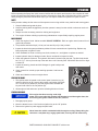
STARTING THE ENGINE
1. The ignition switch is located on the control panel. Insert the key (A)
and turn clockwise to (B), leave at this position until engien light goes
out. Turn the key to position(C) until the engine starts. Release the
key and it will return to the run position (B).
2. Allow engine to idle and warm up before selecting direction of travel.
STOPPING THE ENGINE
If the engine has been running under high
power, let it run at slow idle speed a few minutes to cool the engine down, be-
fore turning the ignition switch to the OFF position.
1. Disengage spray pump.
2. Move the throttle lever to “slow” and turn ignition key to the “o” position.
3. Remove the ignition key and engage the park brake.
Never leave the vehicle unattended with the engine running. Always bring the
vehicle to a complete stop, engage park brake, turn key o and remove key.

12
Operation
PARTS MANUALS AVAILABLE ONLINE AT smithco.com
OPERATION
Before using the Spray Star, the operator and spray technician must familiarize themselves with all of the information on
chemical spraying contained in the Turf Spray Guide.
All testing and calibrating of sprayers is to be done with water, not chemicals. This insures the safety to all involved in
performing the calibration operation. Only after all calibration procedures are completed should chemical be added to the
sprayer.
HILLSIDE OPERATION
Do NOT stop or start suddenly on any slope. Be especially cautious when changing direction. Do NOT operate on slopes
greater than 10°.
BATTERY
Batteries normally produce explosive gases which can cause personal injury. Do not allow ames, sparks or any ignited
object to come near the battery. When charging or working near battery, always shield your eyes and always provide
proper ventilation.
Battery cable should be disconnected before using “Fast Charge”.
Charge battery at 15 amps for 10 minutes or 7 amps for 30 minutes. Do not exceed the recommended charging rate. If
electrolyte starts boiling over, decrease charging.
Always remove grounded (-) battery clamp rst and replace it last. Avoid hazards by:
1. Filling batteries in well-ventilated areas.
2. Wear eye protection and rubber gloves.
3. Avoid breathing fumes when electrolyte is added.
4. Avoid spilling or dripping electrolyte.
Battery Electrolyte is an acidic solution and should be handled with care. If electrolyte
is splashed on any part of your body, ush all contact areas immediately with liberal
amounts of water. Get medical attention immediately.
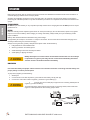
JUMP STARTING
Use of booster battery and jumper cables. Particular care should be used when connecting a booster battery. Use
proper polarity in order to prevent sparks.
To jump start (negative grounded battery):
1. Shield eyes.
2. Connect ends of one cable to positive (+) terminals of each battery, rst (A) then (B).
3. Connect one end of other cable to negative (-) terminal of "good" battery (C).
4. Connect other end of cable (D) to engine block on unit being started (NOT to
negative (-) terminal of battery)
To prevent damage to other electrical components on unit being started, make certain that
engine is at idle speed before disconnecting jumper cables.

13
Operation
PARTS MANUALS AVAILABLE ONLINE AT smithco.com
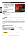
TANK AGITATION
SPRAYER VALVE SETTINGS AND SPRAY TANK AGITATION
The 3-way valve on the suction side of the pump, between the tank and the pump must be open before pump
is engaged. Close this valve only when necessary to clean the lter with spray material in the spray tank.
There is one manual ow control valve on the discharge side of the spray system. This valve controls the
agitator. This valve may be opened as much as necessary to provide hydraulic agitation through the quadra-
jet agitator in the tank bottom. This valve may be partially closed to prevent or reduce foam buildup from the
spray materials inside the tank. When the liquid level in the spray tank reaches a certain level (usually 1-25
gallons (3.8-95 Liters) depending on terrain and other conditions) it may be necessary to close the valve in
the agitator line in order to prevent loss of suction prime.
If your Spray Star is tted with a hose reel, there is a second ball valve on the discharge system to supply ma-
terial to the hose reel.
The Quadrajet agitation system operates with four venturi jets in the tank bottom. These jets have replaceable
orice discs which discharge the following amounts of spay material.
Input to Input to Agitator Agitator Agitator Agitator
Nozzle Agitator Agitator Pressure Pressure Output Output
Diameter in gpm in L/min in psi in bar in gpm in L/min
1
/
8
" 1.9 7.2 25 1.7 6.3 23.8
1
/
8
" 2.7 10.2 50 3.4 10.0 37.9
1
/
8
" 3.8 14.4 100 6.9 15.0 56.8
5
/
32
" 2.8 10.6 25 1.7 7.6 28.8
5
/
32
" 4.2 15.9 50 3.4 12.2 46.2
5
/
32
" 5.5 20.8 100 6.9 17.5 66.2
3
/
16
" 3.6 13.6 25 1.7 9.1 34.4
3
/
16
" 5.6 21.2 50 33.4 14.3 54.1
3
/
16
" 7.9 29.9 100 6.9 18.7 70.8
You can change orice disc sizes to enhance spray system performance.
Smaller discs reduce amount of agitation (desirable in some foaming materi-
als) and make more discharged liquid available for nozzles. Larger (or none)
discs increase amount of agitation and make less discharged liquid available
for nozzles.
AGITATION LINE STRAINER CLEANING
Agitation line strainer is located below the sprayer lter. This strainer catches
impurities that go to the turbo-jet agitation system in the spray tank. It has
a quick disconnect pin on it to remove the bowl. After EVERY use, remove
bowl and clean screen. Replace screen as needed. We recommend a 50
Mesh screen.
DYNAJET
®
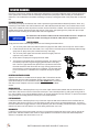
NOZZLE CLEANING
The Nozzle Coil Assembly will need to be taken apart
and cleaned on a regular basis. To take apart and
clean you will need to use two wrenches provided with
the DynaJet
®
System. Loosen the Nozzle assembly
by placing a wrench on the tube assembly and one on
the stainless cap. Hold one in place and turn the other
wrench to loosen assembly. Once apart, clean with wa-
ter and check for deteriorating parts. Replace parts as
needed by ordering the Spare Parts Kit 20-673-01P.

14
Operation
PARTS MANUALS AVAILABLE ONLINE AT smithco.com
SPRAYER CLEANING
One of the most common causes for faulty-pump performance is corrosion inside the pump. Flush the pump and
entire system with a solution that will chemically neutralize the liquid pumped. Mix according to manufacturer’s
directions. This will dissolve most residue remaining in the pump, leaving the inside of the pump clean for the next
use.
TO PREVENT CORROSION
After cleaning the pump as directed, ush it with a permanent type automobile antifreeze (Prestone, Zerex, etc.)
containing a rust inhibitor. Use a 50% solution that is, half antifreeze and half water. Then coat the interior of the
pump with a substance which will prevent corrosion such as Fluid Film or WD40. If unit will not be used for an ex-
tended period of time, disconnect hoses into and out of the pump, seal openings to the pump with caps or tape.
Dispose of uids according to all federal, state and local regulations.
All chemicals and chemical residue must be removed after each use. Dispose of
uids and residue according to all federal, state and local regulations.
SPRAYER CLEANING
Empty tank and clean unit thoroughly after each use following these instructions:
1. Turn o 3-way valve and rinse inside of tank thoroughly with clean water, remove cap from valve to drain.
2. Fill tank ten percent full with clean water, Turn 3-way valve on and start pump and discharge water through
spray hose or spray boom (with nozzles removed), until empty.
3. Turn o 3-way valve again and rinse tank interior thoroughly. Remove
cap from 3-way valve to drain.
4. Rinse exterior of sprayer thoroughly with clean water.
5. This sprayer is equipped with a self cleaning strainer. The strainer uses
the excess pump ow to bypass clogging particles back to the spray
tank. There is a gap between the tapered inner cylinder and the screen
face that causes the inlet uid to ow at a high velocity past the screen
face providing a continuous wash down of particles. For this wash down
to occur a minimum of +GPM/23 l/min is required through the bypass
line.
AGITATION LINE STRAINER CLEANING
Agitation line strainer is located below the sprayer lter. This strainer catches
impurities that go to the turbo-jet agitation system in the spray tank. It has a
quick disconnect pin on it to remove the bowl. After EVERY use, remove bowl
and clean screen. Replace screen as needed. We recommend a 50 Mesh
screen.
MANUAL HOSE REEL
Located at the back of the Spray Star on top of the tank. Open the ball valve located near the manifold valve to
allow uid to ow into the hose reel. Place the lockout pin in the unlocked position by pulling and turning it half a
turn, this will allow you to pull out additional hose or to use the handle and wind up the hose. To prevent movement
during transport or storage place the lockout pin in the locked position.
ELECTRIC HOSE REEL
Located at the back of the Spray Star on top of the tank. Open the ball valve located near the manifold valve to
allow uid to ow into the hose reel. To unwind hose just pull on the hose to get the desired amount. To wind up
the hose make sure the toggle switch is in the ON position, push the momentary push button switch until you have
reeled in the amount of hose desire. Turn o the safety switch when not in use.
FOAM MARKER
Located to the right of the control panel. Use lever on compressor to designate which boom is to be used to dis-
pense foam. Use dial located on the foamer to adjust pressure for the amount of foam that will be dispensed.
Switch on compressor also turns foamer on or o.

15
Diagrams
PARTS MANUALS AVAILABLE ONLINE AT smithco.com
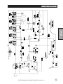
MAIN WIRING DIAGRAM

16
Diagrams
PARTS MANUALS AVAILABLE ONLINE AT smithco.com
ENGINE WIRING DIAGRAM

17
Diagrams
PARTS MANUALS AVAILABLE ONLINE AT smithco.com
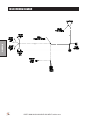
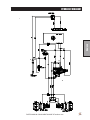
HYDRAULIC DIAGRAM

18
Reference
PARTS MANUALS AVAILABLE ONLINE AT smithco.com
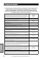
DECLARATION OF CONFORMITY
Business name and full address of the manufacturer ▪ Търговско име и пълен адрес на производителя ▪ Obchodní jméno a plná adresa
výrobce ▪ Producentens firmanavn og fulde adresse ▪ Bedrijfsnaam en volledig adres van de fabrikant ▪ Tootja ärinimi ja täielik aadress ▪
Valmistajan toiminimi ja täydellinen osoite ▪ Nom commercial et adresse complète du fabricant ▪ Firmenname und vollständige Adresse des
Herstellers ▪ Επωνυμία και ταχυδρομική διεύθυνση κατασκευαστή ▪ A gyártó üzleti neve és teljes címe ▪ Ragione sociale e indirizzo
completo del fabbricante ▪ Uzņēmuma nosaukums un pilna ražotāja adrese ▪ Verslo pavadinimas ir pilnas gamintojo adresas ▪ Isem
kummerċjali u indirizz sħiħ tal-fabbrikant ▪ Nazwa firmy i pełny adres producenta ▪ Nome da empresa e endereço completo do fabricante ▪
Denumirea comercială şi adresa completă a producătorului ▪ Obchodný názov a úplná adresa výrobcu ▪ Naziv podjetja in polni naslov
proizvajalca ▪ Nombre de la empresa y dirección completa del fabricante ▪ Tillverkarens företagsnamn och kompletta adress
Smithco Inc.
34 West Avenue
Wayne, PA USA
19087-3311
Product Code ▪ Код на продукта ▪ Kód výrobku ▪ Produktkode ▪ Productcode ▪ Toote kood ▪ Tuotekoodi ▪ Code produit ▪ Produktcode ▪
Κωδικός προϊόντος ▪ Termékkód ▪ Codice prodotto ▪ Produkta kods ▪ Produkto kodas ▪ Kodiċi tal-Prodott ▪ Kod produktu ▪ Código do Produto
▪ Cod produs ▪ Kód výrobku ▪ Oznaka proizvoda ▪ Código de producto ▪ Produktkod
31-000-D
Machine Name ▪ Наименование на машината ▪ Název stroje ▪ Maskinnavn ▪ Machinenaam ▪ Masina nimi ▪ Laitteen nimi ▪ Nom de la
machine ▪ Maschinenbezeichnung ▪ Ονομασία μηχανήματος ▪ Gépnév ▪ Denominazione della macchina ▪ Iekārtas nosaukums ▪ Mašinos
pavadinimas ▪ Isem tal-Magna ▪ Nazwa urządzenia ▪ Nome da Máquina ▪ Numele echipamentului ▪ Názov stroja ▪ Naziv stroja ▪ Nombre de
la máquina ▪ Maskinens namn
Spray Star 3180
Designation ▪ Предназначение ▪ Označení ▪ Betegnelse ▪ Benaming ▪ Nimetus ▪ Tyyppimerkintä ▪ Pažymėjimas ▪ Bezeichnung ▪
Χαρακτηρισμός ▪ Megnevezés ▪ Funzione ▪ Apzīmējums ▪ Lithuanian ▪ Denominazzjoni ▪ Oznaczenie ▪ Designação ▪ Specificaţie ▪ Označenie
▪ Namen stroja ▪ Descripción ▪ Beteckning
Turf Sprayer
Serial Number ▪ Сериен номер ▪ Sériové číslo ▪ Serienummer ▪ Serienummer ▪ Seerianumber ▪ Valmistusnumero ▪ Numéro de série ▪
Seriennummer ▪ Σειριακός αριθμός ▪ Sorozatszám ▪ Numero di serie ▪ Sērijas numurs ▪ Serijos numeris ▪ Numru Serjali ▪ Numer seryjny ▪
Número de Série ▪ Număr de serie ▪ Sériové číslo ▪ Serijska številka ▪ Número de serie ▪ Serienummer
300G500 - 300G900
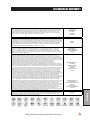
Engine ▪ Двигател ▪ Motor ▪ Motor ▪ Motor ▪ Mootor ▪ Moottori ▪ Moteur ▪ Motor ▪ Μηχανή ▪ Modulnév ▪ Motore ▪ Dzinējs ▪ Variklis ▪ Saħħa
Netta Installata ▪ Silnik ▪ Motor ▪ Motor ▪ Motor ▪ Motor ▪ Motor ▪ Motor
Kubota wg1605
Net Installed Power ▪ Нетна инсталирана мощност ▪ Čistý instalovaný výkon ▪ Installeret nettoeffekt ▪ Netto geïnstalleerd vermogen ▪
Installeeritud netovõimsus ▪ Asennettu nettoteho ▪ Puissance nominale nette ▪ Installierte Nettoleistung ▪ Καθαρή εγκατεστημένη ισχύς ▪
Nettó beépített teljesítmény ▪ Potenza netta installata ▪ Paredzētā tīkla jauda ▪ Grynoji galia ▪ Wisa’ tal-Qtugħ ▪ Moc zainstalowana netto ▪
Potência instalada ▪ Puterea instalată netă ▪ Čistý inštalovaný výkon ▪ Neto vgrajena moč ▪ Potencia instalada neta ▪ Nettoeffekt
57 kW
Conforms to Directives ▪ В съответствие с директивите ▪ Splňuje podmínky směrnic ▪ Er i overensstemmelse med direktiver ▪ Voldoet aan
de richtlijnen ▪ Vastab direktiividele ▪ Direktiivien mukainen ▪ Conforme aux directives ▪ Entspricht Richtlinien ▪ Ακολουθήστε πιστά τις
Οδηγίες ▪ Megfelel az irányelveknek ▪ Conforme alle Direttive ▪ Atbilst direktīvām ▪ Atitinka direktyvų reikalavimus ▪ Valutazzjoni tal-
Konformità ▪ Dyrektywy związane ▪ Cumpre as Directivas ▪ Respectă Directivele ▪ Je v súlade so smernicami ▪ Skladnost z direktivami ▪
Cumple con las Directivas ▪ Uppfyller direktiv
2006/42/EC;
2000/14/EC Annex VI . Part 1
Conformity Assessment ▪ Оценка за съответствие ▪ Hodnocení plnění podmínek ▪ Overensstemmelsesvurdering ▪
Conformiteitsbeoordeling ▪ Vastavushindamine ▪ Vaatimustenmukaisuuden arviointi ▪ Evaluation de conformité ▪ Konformitätsbeurteilung ▪
Διαπίστωση Συμμόρφωσης ▪ Megfelelőség-értékelés ▪ Valutazione della conformità ▪ Atbilstības novērtējums ▪ Atitikties įvertinimas ▪ Livell
tal-Qawwa tal-Ħoss Imkejjel ▪ Ocena zgodności ▪ Avaliação de Conformidade ▪ Evaluarea conformităţii ▪ Vyhodnotenie zhodnosti ▪ Ocena
skladnosti ▪ Evaluación de conformidad ▪ Bedömning av överensstämmelse
2006/42/EC Annex VIII
Measured Sound Power Level ▪ Измерено ниво на звукова мощност ▪ Naměřený akustický výkon ▪ Målte lydstyrkeniveau ▪ Gemeten
geluidsniveau ▪ Mõõdetud helivõimsuse tase ▪ Mitattu äänitehotaso ▪ Niveau de puissance sonore mesuré ▪ Gemessener Schalldruckpegel ▪
Σταθμισμένο επίπεδο ηχητικής ισχύος ▪ Mért hangteljesítményszint ▪ Livello di potenza sonora misurato ▪ Izmērītais skaņas jaudas līmenis ▪
Išmatuotas garso stiprumo lygis ▪ Livell tal-Qawwa tal-Ħoss Iggarantit ▪ Moc akustyczna mierzona ▪ Nível sonoro medido ▪ Nivelul măsurat al
puterii acustice ▪ Nameraná hladina akustického výkonu ▪ Izmerjena raven zvočne moči ▪ Nivel de potencia sonora medido ▪ Uppmätt
ljudeffektsnivå
86dB(A)Lwa
Guaranteed Sound Power Level ▪ Гарантирано ниво на звукова мощност ▪ Garantovaný akustický výkon ▪ Garanteret lydstyrkeniveau ▪
Gegarandeerd geluidsniveau ▪ Garanteeritud helivõimsuse tase ▪ Taattu äänitehotaso ▪ Niveau de puissance sonore garanti ▪ Garantierter
Schalldruckpegel ▪ Εγγυημένο επίπεδο ηχητικής ισχύος ▪ Szavatolt hangteljesítményszint ▪ Livello di potenza sonora garantito ▪ Garantētais
skaņas jaudas līmenis ▪ Garantuotas garso stiprumo lygis ▪ Livell tal-Qawwa tal-Ħoss Iggarantit ▪ Moc akustyczna gwarantowana ▪ Nível
sonoro farantido ▪ Nivelul garantat al puterii acustice ▪ Garantovaná hladina akustického výkonu ▪ Zajamčena raven zvočne moči ▪ Nivel de
potencia sonora garantizado ▪ Garanterad ljudeffektsnivå
88 dB(A)Lwa
Conformity Assessment Procedure (Noise) ▪ Оценка за съответствие на процедурата (Шум) ▪ Postup hodnocení plnění podmínek (hluk) ▪
Procedure for overensstemmelsesvurdering (Støj) ▪ Procedure van de conformiteitsbeoordeling (geluid) ▪ Vastavushindamismenetlus (müra)
▪ Vaatimustenmukaisuuden arviointimenettely (Melu) ▪ Procédure d’évaluation de conformité (bruit) ▪ Konformitätsbeurteilungsverfahren
(Geräusch) ▪ Διαδικασία Αξιολόγησης Συμμόρφωσης (Θόρυβος) ▪ Megfelelőség-értékelési eljárás (Zaj) ▪ Procedura di valutazione della
conformità (rumore) ▪ Atbilstības novērtējuma procedūra (troksnis) ▪ Atitikties įvertinimo procedūra (garsas) ▪ Proċedura tal-Valutazzjoni tal-
Konformità (Ħoss) ▪ Procedura oceny zgodności (poziom hałasu) ▪ Processo de avaliação de conformidade (nível sonoro) Procedura de
evaluare a conformităţii (zgomot) ▪ Postup vyhodnocovania zhodnosti (hluk) ▪ Postopek za ugotavljanje skladnosti (hrup) ▪ Procedimiento de
evaluación de conformidad (ruido) ▪ Procedur för bedömning av överensstämmelse (buller)
2000/14/EC Annex VI Part 1
UK Notified Body for 2000/14/EC ▪ Нотифициран орган в Обединеното кралство за 2000/14/ЕО ▪ Úřad certifikovaný podle směrnice č.
2000/14/EC ▪ Det britiske bemyndigede organ for 2001/14/EF ▪ Engels adviesorgaan voor 2000/14/EG ▪ Ühendkuningriigi teavitatud asutus
direktiivi 2000/14/EÜ mõistes ▪ Direktiivin 2000/14/EY mukainen ilmoitettu tarkastuslaitos Isossa-Britanniassa ▪ Organisme notifié concernant
la directive 2000/14/CE ▪ Britische benannte Stelle für 2000/14/EG ▪ Κοινοποιημένος Οργανισμός Ηνωμένου Βασιλείου για 2000/14/ΕΚ ▪
2000/14/EK – egyesült királyságbeli bejelentett szervezet ▪ Organismo Notificato in GB per 2000/14/CE ▪ 2000/14/EK AK reģistrētā
organizācija ▪ JK notifikuotosios įstaigos 2000/14/EC ▪ Korp Notifikat tar-Renju Unit għal 2000/14/KE ▪ Dopuszczona jednostka badawcza w
Wielkiej Brytanii wg 2000/14/WE ▪ Entidade notificada no Reino Unido para 2000/14/CE ▪ Organism notificat în Marea Britanie pentru
2000/14/CE ▪ Notifikovaný orgán Spojeného kráľovstva pre smernicu 2000/14/ES ▪ Britanski priglašeni organ za 2000/14/ES ▪ Cuerpo
notificado en el Reino Unido para 2000/14/CE ▪ Anmält organ för 2000/14/EG i Storbritannien
Smithco West Inc.
200 West Poplar Avene
Cameron, WI 54822 USA
Operator Ear Noise Level ▪ Оператор на нивото на доловим от ухото шум ▪ Hladina hluku v oblasti uší operátora ▪ Støjniveau i førers
ørehøjde ▪ Geluidsniveau oor bestuurder ▪ Müratase operaatori kõrvas ▪ Melutaso käyttäjän korvan kohdalla ▪ Niveau de bruit à hauteur des
oreilles de l’opérateur ▪ Schallpegel am Bedienerohr ▪ Επίπεδο θορύβου σε λειτουργία ▪ A kezelő fülénél mért zajszint ▪ Livello di potenza
sonora all’orecchio dell’operatore ▪ Trokšņa līmenis pie operatora auss ▪ Dirbančiojo su mašina patiriamo triukšmo lygis ▪ Livell tal-Ħoss fil-
Widna tal-Operatur ▪ Dopuszczalny poziom hałasu dla operatora ▪ Nível sonoro nos ouvidos do operador ▪ Nivelul zgomotului la urechea
operatorului ▪ Hladina hluku pôsobiaca na sluch operátora ▪ Raven hrupa pri ušesu upravljavca ▪ Nivel sonoro en el oído del operador ▪
Ljudnivå vid förarens öra
86 dB(A)Lwa (2006/42/EC)
DECLARATION OF CONFORMITY ▪ ДЕКЛАРАЦИЯ ЗА СЪОТВЕТСТВИЕ ▪ PROHLÁŠENÍ O SHODĚ ▪ OVERENSSTEMMELSESERKLÆRING ▪
CONFORMITEITSVERKLARING ▪ VASTAVUSDEKLARATSIOON ▪ VAATIMUSTENMUKAISUUSVAKUUTUS ▪ DECLARATION DE
CONFORMITE ▪ KONFORMITÄTSERKLÄRUNG ▪ ΔΗΛΩΣΗ ΣΥΜΜΟΡΦΩΣΗΣ ▪ MEGFELELŐSÉGI NYILATKOZAT ▪ DICHIARAZIONE DI
CONFORMITÀ ▪ ATBILSTĪBAS DEKLARĀCIJA ▪ ATITIKTIES DEKLARACIJA ▪ DIKJARAZZJONI TAL-KONFORMITÀ ▪ DEKLARACJA
ZGODNOŚCI ▪ DECLARAÇÃO DE CONFORMIDADE ▪ DECLARAŢIE DE CONFORMITATE ▪ VYHLÁSENIE O ZHODE ▪ IZJAVA O SKLADNOSTI
▪ DECLARACIÓN DE CONFORMIDAD ▪ DEKLARATION OM ÖVERENSSTÄMMELSE
Pagina se încarcă...
Pagina se încarcă...
Pagina se încarcă...
Pagina se încarcă...
Pagina se încarcă...
-
 1
1
-
 2
2
-
 3
3
-
 4
4
-
 5
5
-
 6
6
-
 7
7
-
 8
8
-
 9
9
-
 10
10
-
 11
11
-
 12
12
-
 13
13
-
 14
14
-
 15
15
-
 16
16
-
 17
17
-
 18
18
-
 19
19
-
 20
20
-
 21
21
-
 22
22
-
 23
23
-
 24
24
-
 25
25


Smithco Spray Star 3180 – TeeJet System Manualul proprietarului
- Tip
- Manualul proprietarului
- Acest manual este potrivit și pentru
în alte limbi
Lucrări înrudite
-
Smithco Spray Star 1110 Instrucțiuni de utilizare
-
-
-
-
-
-
-
-
-
Alte documente
-
Simplicity 073035-00 Manual de utilizare
-
-
Makita PM001G Manual de utilizare
-
-
STIHL WP 600 Manual de utilizare
-
Makita EW2050H Manual de utilizare
-
Makita BVF104 Manual de utilizare
-
Dolmar SP76504R Manualul proprietarului
-
Ryobi RAP200 Manualul proprietarului
-
ULTIMATE SPEED UOP 12 B1 Translation Of The Original Instructions