
Montageanleitung 04/2019 - 6917472
Standkonsole geteilt für Vplus
Flachheizkörper Typ 20-33
DE – Standkonsole geteilt für Vplus
Flachheizkörper Typ 20-33
EN - Standing bracket separated for
Vplus panel radiators type 20–33
FR - Socle en kit pour le radiateur pan-
neau Vplus type 20-33
IT - Supporto verticale diviso per elemen-
to riscaldante piatto Vplus tipo 20-33
NL - Steunbeugel voor Vplus paneelradia-
tor type 20-33
CZ - Stojanová konzola je určena pro
panelové radiátory Vplus typu 20-33
SK - Stojanová konzola rozdelená pre
ploché doskové radiátory Vplus typ 20-33
PL - Konsola stojąca podzielona na grzej-
niki płytowe Vplus typ 20-33
RU -Опорная консоль разобрана для
плоского радиатора Vplus тип 20-33
RO - Consolă de susținere împărțită pent-
ru radiatorul plat Vplus tip 20-33
HU - Osztott állókonzol a Vplus lapos
fűtőtesthez típus: 20-33
=+ - 㩭ൠ᭟ᷦ䘲⭘Ҿර
9SOXVᶯᔿ࣐✝ಘ

2
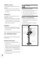
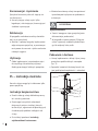
DE – Gebrauchsanleitung
Zulässiger Gebrauch
Die Standskonsole darf nur zur Befestigung
von FTP, PTP und PLP Kermi-Flachheizkörpern
Typ 20-33 und von Baulänge 600-2600 bei
der Anwendungsklasse 2 verwendet werden.
ACHTUNG
Ŷ
Höhe Standkonsolenfüße für Rohboden-
montage ausgelegt. (Abb. 7)
Ŷ
Bei Montage auf Fertigboden müssen die
Standkonsolenfüße, durch den Fachhand-
werker, entsprechend dem Bodenaufbau
gekürzt werden.
Wartung und Reinigung
Eine besondere Wartung der Standkonsolen
ist nicht notwendig.
Ŷ
Reinigen Sie die Standkonsolen ausschließ-
lich mit milden, nicht scheuernden handels-
üblichen Reinigungsmitteln.
Reklamation
Wenden Sie sich im Schadensfall an Ihren
Fachhandwerker!
Ŷ
Lassen Sie die Montage und Reparaturen
ausschließlich vom Fachhandwerker aus-
führen, sonst erlischt Ihr Anspruch nach
dem Gesetz für Sachmängelhaftung.
Entsorgung
Ŷ
Führen Sie die Verpackung und nicht be-
nötigte Teile dem Recycling oder der ord-
nungsgemäßen Entsorgung zu. Beachten
Sie die örtlichen Vorschriften.
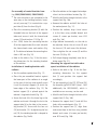
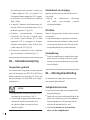
DE – Montageanleitung
Die Standkonsolen dürfen nur von einem
Fachhandwerker montiert werden.
Sicherheitshinweise
Ŷ
Montageanleitung vor der Montage gründ-
lich durchlesen.
Ŷ
Alle Hinweise zu Aufstellort, technischen
Daten, Einsatzgrenzen, Bodenbeschaffen-
heit und Wandabstand beachten.
Ŷ
Nach der Montage die Anleitung dem
Endverbraucher überlassen.
Ŷ
Das Montagematerial nur in der Schutzver-
packung transportieren und lagern.
WARNUNG
Verletzungsgefahr!
Ŷ
Gewicht des Heizkörpers beachten (siehe
Unterlagen des Herstellers).
Ŷ
Ab 25 kg mit Hebeeinrichtung oder
mehreren Personen arbeiten.

3
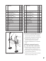
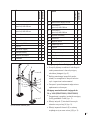
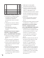
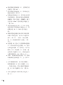
Verpackung und Lieferumfang
Ŷ
Die Verpackung des Heizkörpers auf Un-
ter- und Rückseite im Bereich der unteren
Laschen entfernen (Abb. 2).
Ŷ
Packungsinhalt der Standkonsolen auf Voll-
ständigkeit und Schäden prüfen.
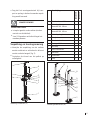
6
5
8
4
7
11
10
9
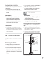
2
1
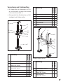
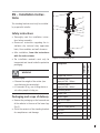
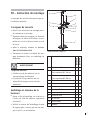
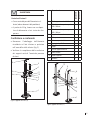
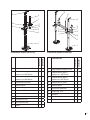
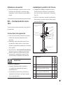
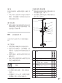
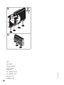
Abbildung Standkonsole (SK)
Bezeichnung
ZB04720001
ZB04730001
1 Standkonsolenfuß 245 mm 1 1
2 Verbindungsrohr +
Oberteil 300 - 500 mm
1-
2 Verbindungsrohr +
Oberteil 600 - 900 mm
-1
3 Verbindungswinkel - -
4 Trägerrohr 1 1
5 Konsolenbock 2 2
Bezeichnung
ZB04720001
ZB04730001
6 Abstützung Typ 20-33 1 1
7 Verschlusskappe 2 2
8 Haken Standkonsole 1 1
9 Gewindestift 1 1
10 Sechskantmutter 1 1
11 Scheibe 1 1
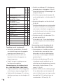
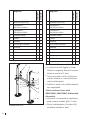
6
3
4
5
12
8
11
10
7
9
2
1
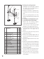
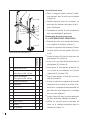
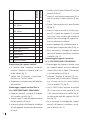
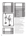
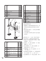
Abbildung Mittelkonsole (MK)
Bezeichnung
ZB04740001
ZB04750001
1 Standkonsolenfuß 245 mm 1 1
2 Verbindungsrohr +
Oberteil 300 - 500 mm
1-
2 Verbindungsrohr +
Oberteil 600 - 900 mm
-1

4
Bezeichnung
ZB04740001
ZB04750001
3 Verbindungswinkel 1 1
4 Trägerrohr 2 2
5 Konsolenbock 4 4
6 Abstützung Typ 20-33 2 2
7 Verschlusskappe 2 2
8 Haken Standkonsole 1 1
9 Gewindestift 2 2
10 Sechskantmutter 1 1
11 Scheibe 5 5
12 Zylinderkopfschraube 4 4
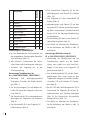
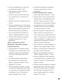
Zuordnung der Standkonsolen
Ŷ
Je nach Baulänge den Flachheizkörper mit
der angegebenen Zuordnung der Standkon-
solen montieren (Abb. 3).
Ŷ
Alle Hinweise, insbesondere die techni-
schen Daten und Einsatzgrenzen, beachten.
Ŷ
Transport und Lagerung nur in der
Schutzverpackung.
Vormontage Standkonsolen bis
BL ≤ 1600 (ZB04720001; ZB04730001)
Ŷ
Werkzeug und Befestigungsmaterial
(Schrauben, Scheiben und Dübel) bereitle-
gen (Abb. 1).
Ŷ
Die Verschlusskappen (7) in die beiden seit-
lichen Öffnungen des Trägerrohrs (4) einste-
cken (Abb. 5).
Ŷ
Die Konsolenböcke (5) in die vorgesehenen
Bohrungen des Trägerrohrs (4) einstecken
(Abb. 5).
Ŷ
Den Gewindestift (9) in das Trägerohr (4)
halb eindrehen (Abb. 5).
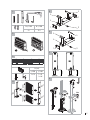
Ŷ
Das vormontierte Trägerrohr (4) auf das
Verbindungsrohr und Oberteil (2) schieben
(Abb. 7/8).
Ŷ
Das Trägerrohr mit dem Gewindestift (9)
fixieren (Abb. 8).
Ŷ
Verbindungsrohr und Oberteil (2) auf den
Konsolenfuß (1) stecken und mit den bereits
ab Werk vormontierten Zylinderschrauben
fixieren (nicht bei Montage Standkonsolen
mit Heizkörper).
Ŷ
Die Abstützung (6) oben in das Oberteil (2)
lagerichtig einstecken (Abb. 8).
Ŷ
Die Maße zur Montage der Standkonso-
len am Heizkörper, der Tabelle in Abb. 10
entnehmen.
Vormontage Mittelkonsolen ab
BL ≥ 1800 (ZB04740001; ZB04750001)
Ŷ
Vormontage der Mittelkonsole wie bei
Standkonsolen, jedoch mit der Abwei-
chung, dass jeweils nur eine Verschluss-
kappe (7) von vorne in ein Trägerrohr (4)
gesteckt wird (Abb. 6).
Ŷ
Den Verbindungswinkel (3) mit den Gewin-
debohrungen nach unten hinten an den
Trägerrohren anlegen und mit den Zylinder-
schrauben (12) und Scheiben (11) befesti-
gen (Abb. 9).
Ŷ
Bei BL 2300 den Verbindungswinkel (3) je
Seite einmal am Trägerrohr (4) mit den Zy-
linderschrauben und Scheiben befestigen
(Abb. 9). Der Abstand der Konsolenfüße
beträgt 267 mm (Abb. 10).
Ŷ
Die Maße zur Montage der Standkonso-
len am Heizkörper, der Tabelle in Abb. 10
entnehmen.

5
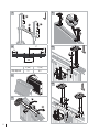
Montage Standkonsolen mit Heizkörper
Ŷ
Den Heizkörper auf den Kopf stellen (Abb.
11).
Ŷ
Die vormontierte Konsole im unteren Teil
des Heizkörpers im Bereich der Laschen
schräg ansetzen und vorsichtig einführen
bis die Konsolenböcke (5) an der Unterkan-
te des Heizkörpers anliegen. (Abb. 12). Der
Konsolenbock (5) wird dabei auf die Heiz-
körperlängsnaht gesetzt (Abb. 13).
Ŷ
Den Haken (8) in die untere Heizkörperla-
sche einhängen und durch das Langloch
des Trägerrohres (4) oder der Bohrung vom
Verbindungswinkel (3) stecken. Mit der
Sechskantmutter (10) und der Scheibe (11)
verschrauben. Durch das Festziehen der
Sechskantmutter (10) wird die Standkon-
sole mit dem Heizkörper verspannt (Abb.
14a/b).
Ŷ
Den Heizkörper auf die Standkonsolenfüße
stellen und am Aufstellungsort positionie-
ren (Abb. 15).
Ŷ
Durch die Bohrungen der Standkonsolenfü-
ße die Bohrlöcher anreißen (Abb. 16a).
Ŷ
Den Heizkörper entfernen und die Löcher
an den gekennzeichneten Stellen bohren
(Abb. 17).
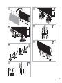
Ŷ
Den Heizkörper in Position bringen, aus-
richten und mit geeigneten Dübeln und
Schrauben (4 Schrauben pro Konsole, max.
Ø10 mm) am Boden befestigen (Abb. 18a).
Ŷ
Heizkörper horizontal ausrichten: Bei der
zu verstellenden Seite den Gewindestift (9)
und die Sechskantmutter (10) lösen und Ab-
stand korrigieren. Danach die Gewindestifte
(9) und die Sechskantmuttern (10) wieder
festziehen (Abb. 20).
Ŷ
Die Verpackung wieder vollständig über
den Heizkörper ziehen (Abb. 21).
Montage Standkonsolenfüße mit an-
schließender Montage des Heizkörpers
Ŷ
Die Maße zur Montage der Standkon-
solenfüße (1) am Boden, der Tabelle in
Abb.10 entnehmen und Standkonsolenfü-
ße platzieren.
Ŷ
Für die Vormontage des FTP, PTP und PLP
kann die im Zubehör erhältliche Montage-
lehre ZK01370001 (ab BL 1800 zusätzlich
ZK01380001) verwendet werden.
Ŷ
Durch die Bohrungen der Standkonsolen-
füße (1) die Bohrlöcher anreißen (Abb.
16b).
Ŷ
Die Standkonsolenfüße (1) entfernen und
die Löcher an den gekennzeichneten Stel-
len bohren (Abb. 17).
Ŷ
Die Standkonsolenfüße (1) in Position
bringen, ausrichten und mit geeigneten
Dübeln und Schrauben (4 Schrauben pro
Konsole, max. Ø10mm) am Boden befesti-
gen (Abb. 18b).
Ŷ
Die Vormontage der Standkonsolen bis BL
≤ 1600 und Mittelkonsolen BL ≥ 1800 oh-
ne Standkonsolenfüße (1) durchführen.
Ŷ
Die vormontierte Konsole im unteren Teil
des Heizkörpers im Bereich der Laschen
schräg ansetzen und vorsichtig einführen
(Abb. 12). Der Konsolenbock (5) wird da-
bei auf die Heizkörperunterkante gesetzt
(Abb.13).

6
Ŷ
Den Haken (8) in die untere Heizkörperla-
sche einhängen und durch das Langloch
des Trägerrohres (4) oder der Bohrung
vom Verbindungswinkel (3) stecken. Mit
der Sechskantmutter (10) und der Scheibe
(11) verschrauben. Durch das Festziehen
der Sechskantmutter (10) wird die Stand-
konsole mit dem Heizkörper verspannt
(Abb.14a/b).
Ŷ
Danach wird der Heizkörper mit dem vor-
montierten Verbindungsrohr (2) auf die
Konsolenfüße (1) aufgesteckt (Abb. 19).
Ŷ
Heizkörper horizontal ausrichten: Bei der
zu verstellenden Seite den Gewindestift (9)
und die Sechskantmutter (10) lösen und
Abstand korrigieren. Danach die Gewin-
destifte (9) und die Sechskantmuttern (10)
wieder festziehen (Abb. 20).
Ŷ
Die Verpackung wieder vollständig über
den Heizkörper ziehen (Abb. 21).
EN – Instructions for use
Permitted use
The standing brackets may only be attached
to Type 20–33 FTP, PTP and PLP Kermi panel
radiators of length 600–2600 in application
class 2.
ATTENTION
Ŷ
Height of support feet configured for
mounting on unfinished floor. (Fig. 7)
Ŷ
For mounting on a finished floor, the
support feet must be shortened in ac-
cordance with the floor structure by the
specialist installer.
Maintenance and cleaning
The standing brackets do not require any spe-
cial maintenance.
Ŷ
To clean the standing brackets, use only
mild, non-abrasive commercial cleaning
agents.
Complaints
In case of damage, contact your specialist
installer!
Ŷ
Ensure that all assembly work and repairs
are carried out by the specialist installer,
as otherwise your statutory right to assert
claims for material defects will expire.
Disposal
Ŷ
Ensure the packaging and any unneeded
parts are recycled, or arrange for their pro-
per disposal. Comply with local regulations.

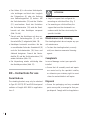
7
EN – Installation instruc-
tions
The standing brackets must only be installed
by a specialist installer.
Safety instructions
Ŷ
Thoroughly read the installation instruc-
tions before assembly.
Ŷ
Observe all instructions regarding the in-
stallation site, technical data, application
limits, floor condition and wall clearance.
Ŷ
After installation, leave the instructions
with the end customer.
Ŷ
The installation materials must only be
transported and stored inside the protective
packaging.
WARNING
Risk of injury!
Ŷ
Observe the weight of the raiator (see
manufactuere documentation).
Ŷ
If it exceeds 25 kg, use a lifting device or
ask other people to help you.
Packaging and scope of delivery
Ŷ
Remove the packaging on the base and rear
of the radiator in the area of the lower lugs
(Fig. 2).
Ŷ
Check the contents of the standing brackets
for completeness and damage.
6
5
8
4
7
11
10
9
2
1
Diagram of standing bracket (SK)
Designation
ZB04720001
ZB04730001
1 Support foot 245 mm 1 1
2 Connecting tube +
upper part 300 – 500 mm
1-
2 Connecting tube +
upper part 600 – 900 mm
-1
3 Connecting bracket - -
4 Support tube 1 1
5 Bracket support 2 2
6 Type 20-33 support 1 1
7 Cap 2 2
8 Hook for standing bracket 1 1
9 Set screw 1 1
10 Hex nut 1 1
11 Washer 1 1

8
6
3
4
5
12
8
11
10
7
9
2
1
Diagram of central bracket (MK)
Designation
ZB04740001
ZB04750001
1 Support foot 245 mm 1 1
2 Connecting tube +
upper part 300 – 500 mm
1-
2 Connecting tube +
upper part 600 – 900 mm
-1
3 Connecting bracket 1 1
4 Support tube 2 2
5 Bracket support 4 4
6 Type 20-33 support 2 2
7 Cap 2 2
8 Hook for standing bracket 1 1
9 Set screw 2 2
10 Hex nut 1 1
11 Washer 5 5
12 Cheese-head screw 4 4
Positioning the standing brackets
Ŷ
Depending on the overall length, install the
flat radiator with the standing brackets in
the specified positions (Fig. 3).
Ŷ
Observe all instructions, in particular tho-
se relating to the technical data and usage
limits.
Ŷ
Ensure the mounting brackets are in their
protective packaging during transport and
storage.
Pre-assembly of standing brackets up to
L ≤ 1600 (ZB04720001; ZB04730001)
Ŷ
Prepare tools and fastening materials
(screws, washers and dowels) (Fig. 1).
Ŷ
Insert the caps (7) into the two lateral
openings on the support tube (4) (Fig. 5).
Ŷ
Insert the bracket supports (5) into the two
designated holes in the support tube (4)
(Fig. 5).
Ŷ
Screw the set screw (9) half way into the
carrier tube (4) (Fig. 5).
Ŷ
Slide the pre-assembled support tube (4)
onto the connecting tube and upper part
(2) (Fig. 7/8).
Ŷ
Secure the support tube with the set screw
(9) (Fig. 8).
Ŷ
Attach the connecting tube and upper part
(2) to the support foot (1) and secure it with
the cheese-head screws, which are already
pre-assembled ex works (not for standing
brackets with radiator).
Ŷ
Insert the support (6) at the top of the up-
per part (2) in the correct position (Fig. 8).
Ŷ
Refer to the table in Fig. 10 for the moun-
ting dimensions for the standing brackets
on the radiator.

9
Pre-assembly of central brackets from
L ≥ 1800 (ZB04740001; ZB04750001)
Ŷ
The central bracket is pre-assembled in the
same way as the standing brackets, howe-
ver only one cap (7) is inserted into a sup-
port tube (4) from the front (Fig. 6).
Ŷ
Place the connecting bracket (3) with the
threaded holes on the back of the support
tubes and secure it with the cheese-head
screws (12) and washers (11) (Fig. 9).
Ŷ
For L 2300, fasten the connecting bracket
(3) to the support tube (4) on each side with
the cheese-head screws and washers (Fig.
9). The distance between the mounting bra-
ckets is 267 mm (Fig. 10).
Ŷ
Refer to the table in Fig. 10 for the moun-
ting dimensions for the standing brackets
on the radiator.
Installation of standing brackets with
radiator
Ŷ
Turn the radiator upside down (Fig. 11).
Ŷ
Place the pre-assembled bracket against
the lower part of the radiator at an angle
in the area of the lugs and carefully insert
it until the bracket supports (5) touch the
lower edge of the radiator. (Fig. 12). The
bracket support (5) is placed against the
radiator's longitudinal weld (Fig. 13).
Ŷ
Secure the hook (8) in the lower lug on the
radiator and insert it through the slot in the
support tube (4) or the hole in the connec-
ting bracket (3). Secure with the hex nut
(10) and washer (11). By tightening the hex
nut (10), the standing bracket is clamped to
the radiator (Fig. 14a/b).
Ŷ
Place the radiator on the support feet and po-
sition it at the installation location (Fig. 15).
Ŷ
Mark the drill holes through the holes in the
support feet (Fig. 16a).
Ŷ
Remove the radiator and drill the holes at
the marked points (Fig. 17).
Ŷ
Position the radiator, align it and secure
it to the floor using suitable dowels and
screws (4 screws per bracket, max. Ø10
mm) (Fig. 18a).
Ŷ
Align radiator horizontally: on the side to
be adjusted, loosen the set screw (9) and
the hex nut (10) and correct the distance.
Then re-tighten the set screws (9) and the
hex nuts (10) (Fig. 20).
Ŷ
Pull the packaging completely over the ra-
diator again (Fig. 21).
Mounting the support feet with subse-
quent installation of the radiator
Ŷ
Refer to the table in Fig. 10 for the floor-
mounting dimensions for the support
feet (1) and position the support feet
accordingly.
Ŷ
For pre-assembly of the FTP, PTP and PLP,
the assembly jig ZK01370001 (from L 1800
additionally the ZK01380001), which is
available as an accessory, can be used.
Ŷ
Mark the drill holes through the holes in the
support feet (1) (Fig. 16b).
Ŷ
Remove the support feet (1) and drill the
holes at the marked points (Fig. 17).
Ŷ
Position the support feet (1), align them
and secure them to the floor using suitable
dowels and screws (4 screws per bracket,
max. Ø10 mm) (Fig. 18b).

10
Ŷ
The standing brackets up to L ≤ 1600 and
centre brackets L ≥ 1800 should be pre-as-
sembled without support feet (1).
Ŷ
Place the pre-assembled bracket against
the lower part of the radiator at an angle in
the area of the lugs and carefully insert the
bracket (Fig. 12). The bracket support (5) is
placed against the radiator's longitudinal
weld (Fig. 13).
Ŷ
Secure the hook (8) in the lower lug on the
radiator and insert it through the slot in the
support tube (4) or the hole in the connec-
ting bracket (3). Secure with the hex nut
(10) and washer (11). By tightening the hex
nut (10), the standing bracket is clamped to
the radiator (Fig. 14a/b).
Ŷ
Afterwards the radiator with the pre-assem-
bled connecting tube (2) is attached to the
support feet (1) (Fig. 19).
Ŷ
Align radiator horizontally: on the side to
be adjusted, loosen the set screw (9) and
the hex nut (10) and correct the distance.
Then re-tighten the set screws (9) and the
hex nuts (10) (Fig. 20).
Ŷ
Pull the packaging completely over the ra-
diator again (Fig. 21).
FR – Instructions d'utilisa-
tion
Utilisation conforme
Le socle ne doit être utilisé que pour la fixation
des radiateurs panneaux FTP, PTP et PLP Kermi
du type 20 à 33 et d’une longueur totale 600-
2600 pour l'utilisation de classe 2.
ATTENTION
Ŷ
Pieds de socle hauts conçus pour le mon-
tage sur sol brut. (schéma 7).
Ŷ
Lors du montage sur une dalle, faire rac-
courcir les pieds du socle par un installa-
teur spécialisé en fonction de la structure
du sol.
Entretien et nettoyage
Le socle ne nécessite pas d’entretien parti-
culier.
Ŷ
Nettoyez le socle exclusivement avec des
produits de nettoyage disponibles dans le
commerce, doux et non abrasifs.
Réclamation
En cas de défaut, veuillez vous adresser à
votre installateur spécialisé!
Ŷ
Faire réaliser le montage et les réparations
par un installateur spécialisé exclusivement.
Tout manquement à cette consigne entrai-
ne une annulation de la responsabilité pour
vice caché au regard de la loi.
Traitement des déchets
Ŷ
Mettre l'emballage et les pièces inutiles
dans le système de recyclage ou dans un
point de collecte conforme. Respecter les
prescriptions locales.

11
FR – Instruction de montage
Le montage du socle doit être exécuté par un
installateur spécialisé.
Consignes de sécurité
Ŷ
Bien lire les instructions de montage avant
de commencer ce montage.
Ŷ
Respecter toutes les consignes, les données
techniques, les limites d’utilisation, les pro-
priétés du sol et la distance entre le socle
et le mur.
Ŷ
Après le montage, remettre les instruc-
tions à l'utilisateur final.
Ŷ
Transporter et stocker le matériel de mon-
tage uniquement dans un emballage de
protection.
AVERTISSEMENT
Risque de blessure!
Ŷ
Vérifier le poids du radiateur (voir la
documentation du fabricant).
Ŷ
À partir de 25 kg, travailler avec un
dispositif de levage ou avec d’autres
personnes.
Emballage et étendue de la
livraison
Ŷ
Retirer le film d’emballage sur le dessus et
l’arrière, du côté des attaches supérieures
(schéma 2).
Ŷ
Vérifier le contenu de l’emballage du pied
de support pour s’assurer que rien ne man-
que et qu’il n’y a aucun défaut.
6
5
8
4
7
11
10
9
2
1
Schéma du pied de support (PS)
Description
ZB04720001
ZB04730001
1 Pied de socle 245mm 1 1
2 Tube de raccordement+
Partie supérieure 300 - 500 mm
1-
2 Tube de raccordement+
Partie supérieure 600 - 900 mm
-1
3 Coude de raccordement - -
4 Tube porteur 1 1
5 Étrier du socle 2 2
6 Appui type 20-33 1 1
7 Capuchon de fermeture 2 2
8 Crochet de socle 1 1
9 Vis sans tête 1 1
10 Écrous six pans 1 1
11 Rondelle 1 1

12
6
3
4
5
12
8
11
10
7
9
2
1
Schéma de console intermédiaire (CI)
Description
ZB04740001
ZB04750001
1 Pied de socle 245mm 1 1
2 Tube de raccordement+
Partie supérieure 300 - 500 mm
1-
2 Tube de raccordement+
Partie supérieure 600 - 900 mm
-1
3 Coude de raccordement 1 1
4 Tube porteur 2 2
5 Étrier du socle 4 4
6 Appui type 20-33 2 2
7 Capuchon de fermeture 2 2
8 Crochet de socle 1 1
9 Vis sans tête 2 2
10 Écrous six pans 1 1
11 Rondelle 5 5
12 Vis cylindrique 4 4
Association du socle
Ŷ
Selon la longueur totale, monter le radia-
teur panneau avec le socle associé indiqué
(schéma 3).
Ŷ
Veuillez respecter toutes les consignes, en
particulier les données techniques et les li-
mites d’utilisation.
Ŷ
Transporter et stocker le socle uniquement
dans un emballage de protection.
Prémontage du socle jusqu’à une
LT ≤ 1600 (ZB04720001; ZB04730001)
Ŷ
Préparer les outils et le matériel de fixation
(vis, rondelles et chevilles) (schéma 1).
Ŷ
Insérer les capuchons de fermeture (7) dans
les deux orifices du tube porteur (4) (sché-
ma 5).
Ŷ
Insérer les étriers (5) dans les deux trous du
tube porteur (4) (schéma 5).
Ŷ
Visser la vis sans tête (9) de moitié dans le
tube porteur (4) (schéma 5).
Ŷ
Faire glisser le tube porteur prémonté (4)
sur le tube de raccordement et la partie
supérieure (2) (schémas 7/8).
Ŷ
Fixer le tube porteur à l’aide de la vis sans
tête (9) (schéma 8).
Ŷ
Insérer le tube de raccordement et la partie
supérieure (2) sur le pied (1) et le fixer à l’ai-
de de la vis cylindrique livrée prémontée (ne
pas effectuer cette étape pour le montage
du socle avec radiateur).
Ŷ
Insérer l’appui (6) dans la partie supérieure
(2) dans la position adéquate (schéma 8).
Ŷ
Vérifier les mesures pour le montage du
socle sur le radiateur présentées dans le
tableau du schéma 10.

13
Prémontage des consoles intermédiaires
à partir d'une
LT ≥ 1800 (ZB04740001; ZB04750001)
Ŷ
Pré-montage de la console intermédiaire
identique à celui du socle, à la différence
cependant que seulement un capuchon de
fermeture (7) doit être inséré par devant
dans le tube porteur (4) (schéma 6).
Ŷ
Placer le coude de raccordement (3) avec
les trous taraudés vers le bas à l’arrière du
tube porteur et le fixer à l’aide de la vis
cylindrique (12) et les rondelles (11) (sché-
ma 9).
Ŷ
En cas de longueur totale de 2300, fixer
le coude de raccordement (3) de chaque
côté sur le tube porteur (4) à l’aide de la
vis cylindrique et des rondelles (schéma 9).
Les pieds doivent être écartés de 267mm
(schéma 10).
Ŷ
Vérifier les mesures pour le montage du
socle sur le radiateur présentées dans le
tableau du schéma 10.
Montage du socle avec le radiateur
Ŷ
Mettre le radiateur tête en bas (schéma 11).
Ŷ
Placer le support prémonté en biais dans la
partie inférieure du radiateur, vers les atta-
ches et l’insérer avec précaution jusqu’à ce
que les étriers (5) se trouvent sur le bord
inférieur du radiateur. (Schéma 12). Les ét-
riers du support (5) sont alors placés sur la
soudure longitudinale du radiateur (schéma
13).
Ŷ
Accrocher les crochets (8) dans l’attache
inférieure du radiateur et l’insérer dans le
trou oblong du tube porteur (4) ou dans le
trou du coude de raccordement (3). Visser à
l’aide de l’écrou à six pans (10) et de la ron-
delle (11). Accoupler ensuite le socle avec le
radiateur en serrant l’écrou à six pans (10)
(schéma 14a/b).
Ŷ
Placer le radiateur sur le pied du socle et le
positionner sur le lieu de montage (schéma
15).
Ŷ
Marquer les orifices à travers ceux des pieds
du socle (schéma 16a).
Ŷ
Retirer le radiateur et percer les trous en
suivant les marquages (schéma 17).
Ŷ
Mettre le radiateur en position, l’aligner et
le fixer au sol avec des chevilles et des vis
adaptées (4vis par support, max. Ø10 mm)
(schéma 18a).
Ŷ
Positionner le radiateur à l’horizontal: Dé-
serrer la vis sans tête (9) et l’écrou à six pans
(10) sur le côté à régler et corriger l’écarte-
ment. Resserrer ensuite la vis sans tête (9)
et l’écrou à six pans (10) (schéma 20).
Ŷ
Replacer complètement l’emballage autour
du radiateur (schéma 21).
Montage des pieds de socle avec mon-
tage ultérieur du radiateur
Ŷ
Vérifier les mesures pour le montage des
pieds du socle (1) sur le sol, présentées
dans le tableau du schéma 10 et placer les
pieds du socle.
Ŷ
Pour le prémontage des modèles FTP, PTP et
PLP, vous pouvez utiliser le gabarit de mon-
tage ZK01370001 que vous trouverez dans
les accessoires (à partir d’une longueur to-
tale de 1800 rajouter le ZK01380001).

14
Ŷ
Marquer les orifices à travers ceux des pieds
du socle (1) (schéma 16b).
Ŷ
Retirer les pieds du socle (1) et percer les
trous en suivant les marquages (schéma
17).
Ŷ
Mettre les pieds du socle (1) en position, les
aligner et les fixer au sol avec des chevilles
et des vis adaptées (4vis par support, max.
Ø10 mm) (schéma 18b).
Ŷ
Effectuer le prémontage du socle jusqu’à
une LT ≤ 1600 et des consoles intermédiai-
res jusqu’à une LT de ≥ 1800 sans les pieds
du socle (1).
Ŷ
Placer le socle prémonté en biais dans la
partie inférieure du radiateur, vers les atta-
ches et l’insérer avec précaution.
IT – Istruzioni d’uso
Uso consentito
Il supporto verticale può essere utilizzato solo
per fissare elementi riscaldanti piatti Kermi
FTP, PTP e PLP di tipo 20-33 e di lunghezza
strutturale 600-2600 nella classe di applica-
zione 2.
ATTENZIONE
Ŷ
P
iedi elevati per il montaggio a pavimen-
to grezzo. (fig. 7)
Ŷ
Nel montaggio su pavimento finito i pie-
di del supporto devono essere accorciati
da un artigiano specializzato in base al
tipo di pavimento.
Manutenzione e pulizia
Non è necessaria una particolare manuten-
zione dei supporti verticali.
Ŷ
Pulire i supporti verticali esclusivamente
con comuni detergenti delicati non abrasivi.
Reclami
In caso di danni, rivolgersi a un artigiano
specializzato!
Ŷ
Fare eseguire montaggio e riparazioni
esclusivamente da artigiani specializzati,
altrimenti decade il diritto di garanzia.
Smaltimento
Ŷ
Conferire l’imballaggio e i componenti non
necessari in un centro di riciclaggio o smal-
tirli conformemente alle norme in materia.
Rispettare le norme locali vigenti in materia.
IT – Istruzioni di montaggio
i supporti verticali possono essere montati
solo da un artigiano specializzato.
Avvertenze di sicurezza
Ŷ
Leggere attentamente le istruzioni prima
del montaggio.
Ŷ
Tutte le informazioni su punto di installa-
zione, dati tecnici, limiti di utilizzo, con-
formazione del pavimento e distanza dalla
parete.
Ŷ
Dopo il montaggio, bisogna lasciare queste
istruzioni all'utente finale.
Ŷ
Trasportare e conservare il materiale di mon-
taggio sempre nell’imballaggio protettivo.

15
AVVERTENZA
Pericolo di lesioni!
Ŷ
Tenere conto del peso dell’elemento riscal-
dante (vedere documenti del produttore).
Ŷ
A partire da 25 kg, lavorare con un disposi-
tivo di sollevamento o farsi aiutare da altre
persone.
Confezione e contenuto
Ŷ
Rimuovere l’imballaggio dell’elemento
riscaldante sul lato inferiore e posteriore
nell'area delle staffe inferiori (fig. 2).
Ŷ
Verificare la completezza della confezione
dei supporti verticali l’eventuale presenza
di danni.
6
5
8
4
7
11
10
9
2
1
Figura supporto verticale (CV)
Denominazione
ZB04720001
ZB04730001
1 Piede supporto verticale 245 mm 1 1
2 Tubo di raccordo + parte superiore
300 - 500 mm
1-
2 Tubo di raccordo + parte superiore
600 - 900 mm
-1
3 Angolare di raccordo - -
4 Tubo portante 1 1
5 Attacco corpo riscaldante 2 2
6 Appoggio tipo 20-33 1 1
7 Tappo 2 2
8 Gancio supporto verticale 1 1
9 Perno filettato 1 1
10 Dado esagonale 1 1
11 Rondella 1 1
6
3
4
5
12
8
11
10
7
9
2
1
Figura supporto centrale (CC)

16
Denominazione
ZB04740001
ZB04750001
1 Piede supporto verticale 245 mm 1 1
2 Tubo di raccordo + parte superiore
300 - 500 mm
1-
2 Tubo di raccordo + parte superiore
600 - 900 mm
-1
3 Angolare di raccordo 1 1
4 Tubo portante 2 2
5 Attacco corpo riscaldante 4 4
6 Appoggio tipo 20-33 2 2
7 Tappo 2 2
8 Gancio supporto verticale 1 1
9 Perno filettato 2 2
10 Dado esagonale 1 1
11 Rondella 5 5
12 Vite a testa cilindrica 4 4
Disposizione dei supporti verticali
Ŷ
A seconda della lunghezza strutturale,
montare l’elemento riscaldante piatto nel
modo indicato (fig. 3).
Ŷ
Seguire tutte le istruzioni, in particolare i
dati tecnici e i limiti di utilizzo.
Ŷ
Trasportare e conservare solo nell’imballag-
gio protettivo.
Premotaggio supporti verticali fino a
LS ≤ 1600 (ZB04720001; ZB04730001)
Ŷ
Preparare strumenti e materiali di fissaggio
(viti, rondelle e tasselli) (fig. 1).
Ŷ
Inserire i tappi (7) nelle due aperture laterali
del tubo portante (4) (fig. 5).
Ŷ
Inserire gli attacchi dell’elemento riscaldante
(5) nelle apposite forature del tubo portante
(4) (fig. 5).
Ŷ
Avvitare a metà il perno filettato (9) nel tubo
portante (4) (fig. 5).
Ŷ
Inserire il tubo portante premontato (4) su
tubo di raccordo e parte superiore (2) (fig.
7/8).
Ŷ
Fissare il tubo portante con il perno filettato
(9) (fig. 8).
Ŷ
Inserire il tubo di raccordo e la parte supe-
riore (2) sul piede del supporto (1) e fissarli
con la vite a testa cilindrica già montata di
fabbrica (non nel montaggio di supporti ver-
ticali con elemento riscaldante).
Ŷ
Inserire l’appoggio (6) correttamente da so-
pra nella parte superiore del tubo (2) (fig. 8).
Ŷ
Per le misure per il montaggio dei supporti
verticali sull’elemento riscaldante, consultare
la tabella in fig. 10.
Premontaggio supporti centrali da
LS ≥ 1800 (ZB04740001; ZB04750001)
Ŷ
Premontaggio del supporto centrale come
per i supporti verticali, ma con la differenza
che va infilato solo un tappo (7) da davanti
in un tubo portante (4) (fig. 6).
Ŷ
Collocare l’angolare di raccordo (3) con i
fori filettati verso il basso dietro i tubi port-
anti e fissarlo con le viti a testa cilindrica
(12) e le rondelle (11) (fig. 9).
Ŷ
Con LS 2300, fissare l’angolare di raccordo
(3) su ciascun lato al tubo portante (4) con
le viti a testa cilindrica e le rondelle (fig. 9).
La distanza dei piedi del supporto è di 267
mm (fig. 10).
Ŷ
Per le misure per il montaggio dei supporti
verticali sull’elemento riscaldante, consul-
tare la tabella in fig. 10.

17
Montaggio dei supporti verticali all’ele-
mento riscaldante
Ŷ
Rovesciare l’elemento riscaldante (fig. 11).
Ŷ
Collocare il supporto premontato in ob-
liquo nella parte inferiore dell’elemento
riscaldante in corrispondenza delle staffe
e inserire con cautela fino agli attacchi (5)
sul bordo inferiore dell’elemento riscal-
dante. (fig. 12). L’attacco (5) va collocato
sulla saldatura longitudinale dell’elemento
riscaldante (fig. 13).
Ŷ
Inserire il gancio (8) nella staffa inferiore
dell’elemento riscaldante e attraverso il
foro longitudinale del tubo portante (4) o
il foro dell’angolare di raccordo (3). Avvita-
re con il dado esagonale (10) e la rondel-
la (11). Stringendo il dado esagonale (10)
il supporto verticale si fissa all’elemento
riscaldante (figg. 14a/b).
Ŷ
Rovesciare nuovamente l’elemento riscal-
dante in modo che poggi sui piedi del sup-
porto verticale e posizionarlo sul punto di
installazione (fig. 15).
Ŷ
Segnare i punti da forare tramite i fori dei
piedi del supporto verticale (fig. 16a).
Ŷ
Rimuovere l’elemento riscaldante ed ese-
guire i fori sui punti segnati (fig. 17).
Ŷ
Portare l’elemento riscaldante in posizione,
orientarlo e fissarlo al pavimento con viti e
tasselli adeguati (4 viti per supporto, max.
Ø10 mm) (fig. 18a).
Ŷ
Orientare orizzontalmente l’elemento
riscaldante: Sul lato che si intende spost-
are, svitare il perno filettato (9) e il dado
esagonale (10) e correggere la distanza.
Stringere nuovamente i perni filettati (9) e
i dadi esagonali (10) (fig. 20).
Ŷ
Ricollocare nuovamente l’intero imballag-
gio sull’elemento riscaldante (fig. 21).
Montaggio dei piedi del supporto verti-
cale seguito dal montaggio dell’elemen-
to riscaldante
Ŷ
Per le misure per il montaggio dei piedi del
supporto verticale (1) al pavimento, consul-
tare la tabella in fig. 10.
Ŷ
Per il premontaggio di FTP, PTP e PLP può
essere utilizzata la guida compresa tra gli
accessori ZK01370001 (da LS 1800 anche
ZK01380001).
Ŷ
Segnare i punti da forare tramite i fori dei
piedi del supporto verticale (1) (fig. 16b).
Ŷ
Rimuovere i piedi del supporto verticale (1)
ed eseguire i fori sui punti segnati (fig. 17).
Ŷ
Portare i piedi del supporto verticale (1) in
posizione, orientarli e fissarli al pavimento
con viti e tasselli adeguati (4 viti per sup-
porto, max. Ø 10 mm) (fig. 18b).
Ŷ
Eseguire il premontaggio dei supporti ver-
ticali fino alla LS ≤ 1600 e dei supporti
centrali LS ≥ 1800 senza piedi del supporto
verticale (1).
Ŷ
Collocare il supporto premontato sul lato
inferiore dell’elemento riscaldante in cor-
rispondenza delle staffe e inserirlo con cau-
tela (fig. 12). L’attacco (5) va collocato sul
bordo inferiore dell’elemento riscaldante
(fig. 13).
Ŷ
Inserire il gancio (8) nella staffa inferiore
dell’elemento riscaldante e attraverso il fo-
ro longitudinale del tubo portante (4) o il

18
foro dell’angolare di raccordo. Avvitare con
il dado esagonale (10) e la rondella (11).
Stringendo il dado esagonale (10) il suppor-
to verticale si fissa all’elemento riscaldante
(figg. 14a/b).
Ŷ
In seguito, l’elemento riscaldante viene infi-
lato nel tubo di raccordo premontato (2) sui
piedi del supporto (1) (fig. 19).
Ŷ
Orientare orizzontalmente l’elemento
riscaldante: Sul lato che si intende spost-
are, svitare il perno filettato (9) e il dado
esagonale (10) e correggere la distanza.
Stringere nuovamente i perni filettati (9) e
i dadi esagonali (10) (fig. 20).
Ŷ
Ricollocare nuovamente l’intero imballag-
gio sull’elemento riscaldante (fig. 21).
NL – Gebruiksaanwijzing
Toegestaan gebruik
De standconsole mag alleen worden gebruikt
voor het bevestigen van FTP, PTP en PLP Kermi
vlakke radiatoren van het type 20-33 en met
een bouwlengte van 600-2600 voor toepas-
singsklasse 2.
LET OP
Ŷ
Hoogte van de standconsolevoeten voor
montage op de ruwe vloer. (fig. 7)
Ŷ
Bij montage op geprefabriceerde vloeren
moeten de standconsolevoeten door
de vakman volgens de vloerstructuur
worden ingekort.
Onderhoud en reiniging
Speciaal onderhoud voor de standconsole is
niet nodig.
Ŷ
Reinig de standconsole uitsluitend
met milde, niet-schurende, normale
reinigingsmiddelen.
Klachten
Neem in het geval van schade contact op met
uw vakman!
Ŷ
Laat de montage en reparatie uitsluitend
uitvoeren door een vakman, anders vervalt
uw aanspraak op grond van de wet op de
aansprakelijkheid voor materiaalfouten.
Verwijdering
Ŷ
Stuur de verpakking en ongebruikte onder-
delen op voor recycling of correcte verwij-
dering. Let op de plaatselijke voorschriften
voor installatie.
NL – Montagehandleiding
De standconsole mag alleen door een vak-
man worden geïnstalleerd.
Veiligheidsinstructies
Ŷ
Lees voor de montage de montagehandlei-
ding grondig door.
Ŷ
Neem alle instructies met betrekking tot de
plaats van opstelling, technische gegevens,
toepassingsgrenzen, de toestand van de
vloer en de wandafstand in acht.
Ŷ
Geef de instructies na de installatie
door aan de eindgebruiker.

19
Ŷ
Zorg dat het montagemateriaal bij trans-
port en opslag in de beschermende verpak-
king wordt bewaard.
WAARSCHUWING
Gevaar voor letsel!
Ŷ
Let op het gewicht van de radiator (zie docu-
mentatie van de fabrikant).
Ŷ
Vanaf 25 kg werken met hefinrichting of met
meerdere personen.
Verpakking en leveringsomvang
Ŷ
Verwijder de verpakking van de radiator
aan de onderkant en achterkant in de buurt
van de onderste beugels (fig. 2).
Ŷ
Controleer de inhoud van het pakket op
volledigheid.
6
5
8
4
7
11
10
9
2
1
Afbeelding standconsole (SC)
Omschrijving
ZB04720001
ZB04730001
1 Standconsole-voet 245 mm 1 1
2 Verbindingsbuis +
bovendeel 300 - 500 mm
1-
2 Verbindingsbuis +
bovendeel 600 - 900 mm
-1
3 Verbindingsbeugel - -
4 Draagbuis 1 1
5 Consolestandaard 2 2
6 Steuntype 20-33 1 1
7 Afsluitkap 2 2
8 Haken standconsole 1 1
9 Stelschroef 1 1
10 Zeskantmoer 1 1
11 Schijf 1 1
6
3
4
5
12
8
11
10
7
9
2
1
Afbeelding middenconsole (MC)

20
Omschrijving
ZB04740001
ZB04750001
1 Standconsole-voet 245 mm 1 1
2 Verbindingsbuis +
bovendeel 300 - 500 mm
1-
2 Verbindingsbuis +
bovendeel 600 - 900 mm
-1
3 Verbindingsbeugel 1 1
4 Draagbuis 2 2
5 Consolestandaard 4 4
6 Steuntype 20-33 2 2
7 Afsluitkap 2 2
8 Haken standconsole 1 1
9 Stelschroef 2 2
10 Zeskantmoer 1 1
11 Schijf 5 5
12 Cilinderkopschroef 4 4
Toewijzing van de standconsole
Ŷ
Monteer de paneelradiator, afhankelijk
van de totale lengte, met de opgegeven
toewijzing van de beugels (fig. 3).
Ŷ
Neem alle instructies in acht, in het
bijzonder de technische gegevens en
toepassingsgrenzen.
Ŷ
Zorg bij transport en opslag voor een
beschermende verpakking.
Voormontage van de standconsole tot
BL ≤ 1600 (ZB04720001; ZB04730001)
Ŷ
Zorg voor gereedschap en bevestigingsmate-
riaal (schroeven, ringen en pluggen) (fig. 1).
Ŷ
Steek de afdichtingskappen (7) in de twee
zijdelingse openingen van de draagbuis (4)
(fig. 5).
Ŷ
Steek de consoledragers (5) in de daarvoor
bestemde gaten in de draagbuis (4) (fig. 5).
Ŷ
Schroef de stelschroef (9) halverwege in de
draagbuis (4) (fig. 5).
Ŷ
Schuif de voorgemonteerde draagbuis (4)
op de verbindingsbuis en het bovendeel (2)
(fig. 7/8).
Ŷ
Bevestig de draagbuis met de stelschroef
(9) (fig. 8).
Ŷ
Plaats de verbindingsbuis en het bovendeel
(2) op de consolevoet (1) en bevestig deze
met de reeds in de fabriek voorgemonteer-
de cilinderschroeven (niet voor de montage
van de standconsole met radiator).
Ŷ
Plaats de steun (6) in het bovendeel (2) in
de juiste positie (fig. 8).
Ŷ
Zie de tabel in fig. 10 voor de afmetingen
voor de montage van de standconsole op
de radiator.
Voormontage van de standconsole tot
BL ≤ 1800 (ZB04740001; ZB04750001)
Ŷ
Voormontage van de middenconsole zoals
bij standconsoles, maar met de uitzon-
dering dat er slechts één afdichtingskap
(7) van voren in een draagbuis (4) wordt
gestoken (fig. 6).
Ŷ
Plaats de verbindingsbeugel (3) met de
schroefgaten aan de onderkant aan de
achterkant van de draagbuizen en bevestig
deze met de cilinderschroeven (12) en
ringen (11) (fig. 9).
Ŷ
Bij de BL 2300 moet de verbindingsbeugel
(3) aan beide zijden van de draagbuis (4)
met de cilinderschroeven en ringen worden
bevestigd (fig. 9). De afstand tussen de
consolevoeten is 267 mm (fig. 10).
Pagina se încarcă...
Pagina se încarcă...
Pagina se încarcă...
Pagina se încarcă...
Pagina se încarcă...
Pagina se încarcă...
Pagina se încarcă...
Pagina se încarcă...
Pagina se încarcă...
Pagina se încarcă...
Pagina se încarcă...
Pagina se încarcă...
Pagina se încarcă...
Pagina se încarcă...
Pagina se încarcă...
Pagina se încarcă...
Pagina se încarcă...
Pagina se încarcă...
Pagina se încarcă...
Pagina se încarcă...
Pagina se încarcă...
Pagina se încarcă...
Pagina se încarcă...
Pagina se încarcă...
Pagina se încarcă...
Pagina se încarcă...
Pagina se încarcă...
Pagina se încarcă...
Pagina se încarcă...
Pagina se încarcă...
Pagina se încarcă...
Pagina se încarcă...
Pagina se încarcă...
Pagina se încarcă...
-
 1
1
-
 2
2
-
 3
3
-
 4
4
-
 5
5
-
 6
6
-
 7
7
-
 8
8
-
 9
9
-
 10
10
-
 11
11
-
 12
12
-
 13
13
-
 14
14
-
 15
15
-
 16
16
-
 17
17
-
 18
18
-
 19
19
-
 20
20
-
 21
21
-
 22
22
-
 23
23
-
 24
24
-
 25
25
-
 26
26
-
 27
27
-
 28
28
-
 29
29
-
 30
30
-
 31
31
-
 32
32
-
 33
33
-
 34
34
-
 35
35
-
 36
36
-
 37
37
-
 38
38
-
 39
39
-
 40
40
-
 41
41
-
 42
42
-
 43
43
-
 44
44
-
 45
45
-
 46
46
-
 47
47
-
 48
48
-
 49
49
-
 50
50
-
 51
51
-
 52
52
-
 53
53
-
 54
54


Kermi ZB04730001 Mounting instructions
- Tip
- Mounting instructions
- Acest manual este potrivit și pentru
în alte limbi
- français: Kermi ZB04730001
- slovenčina: Kermi ZB04730001
- polski: Kermi ZB04730001
Lucrări înrudite
Alte documente
-
 Vogel & Noot WIEN-LEFT Assembly And Operating Manual
-
 VOGEL&NOOT BERLIN-VM Assembly And Operating Manual
-
 VOGEL&NOOT DELLA WAVE Assembly And Operating Manual
-
 Beco EFS7700W Manual de utilizare
-
Miele APCL WOD Fitting Instructions Manual
-
Eurom GOLDEN 1800 Comfort RC Manual de utilizare
-
Solac BATH Mod RC8200 Manualul proprietarului
-
Hendi 272701, 272602 Patio Heater Manual de utilizare
-
Adler AD 7807 Instrucțiuni de utilizare
-
Thomas Bravo 20 Manualul proprietarului


