Ubiquiti UniFi Ghid de inițiere rapidă
- Categorie
- Antene de rețea
- Tip
- Ghid de inițiere rapidă

802.11ac Dual-Radio AP
with Public Address System
Model: UAP-AC-EDU

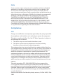
Introduction
Thank you for purchasing the Ubiquiti Networks®
UniFi®802.11ac Dual-Radio AP with Public Address System.
This Quick Start Guide is designed to guide you through
installation and also includes warranty terms.
IMPORTANT: The UAP-AC-EDU requires the UniFi Controller
v
4.9.5
or higher, available at: downloads.ubnt.com/unifi
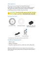
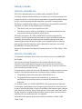
Package Contents
UniFi AP AC EDU Mounting Template Gigabit PoE* (48V, 0.5A)
with Mounting Bracket
802.11ac Dual-Radio AP
with Public Address System
Model: UAP-AC-EDU
Power Cord* Quick Start Guide
* Included only in the single-pack of the UAP-AC-EDU.
Installation Requirements
• CAT5/6 cable
• Phillips screwdriver
• Drywall or keyhole saw (to cut the hole in the ceiling tile)
TERMS OF USE: All Ethernet cabling runs must use CAT5 (or above). It is the customer’s
responsibility to follow local country regulations, including operation within legal frequency
channels, output power, indoor cabling requirements, and Dynamic Frequency Selection
(DFS) requirements.

System Requirements
• Linux, MacOSX, or Microsoft Windows 7/8/10
• Java Runtime Environment 1.6 (1.8 or above recommended)
• Web Browser: Google Chrome (Other browsers may have
limited functionality.)
• UniFi Controller software v4.9.5 or newer (available at:
downloads.ubnt.com/unifi)
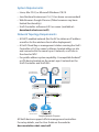
Network Topology Requirements
• A DHCP-enabled network (for the AP to obtain an IP address
as well as for the wireless clients after deployment)
• A UniFi Cloud Key or management station running the UniFi
Controller v4.9.5 (or newer) software, located either on-site
and connected to the same Layer-2 network, or off-site in
the cloud or NOC
• For public address system capability: A compatible Android
™
or iOS device located on the same Layer-2 network as the
UniFi Controller and UniFi APs
US-16-150W
USG-PRO-4
(DHCP Server)
Internet
UAP-AC-EDU UAP-AC-EDU
LAN
WAN
UniFi Cloud Key
(UniFi Controller)
UAP-AC Outdoor
Remote Access to
UniFi Controller
Sample Network Diagram
All UniFi devices support off-site management controllers.
For setup details, see the User Guide on the website:
documentation.ubnt.com/unifi

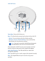
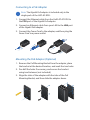
Hardware Overview
The UniFi AP AC EDU is comprised of the Speaker Assembly
and UniFi AP.
USB Cable
Speaker
Assembly
UniFi AP
Ethernet Cable
Safety
Wire
Back of the Speaker Assembly
Main Port
Clamp Bracket
Main This Gigabit Ethernet port is used to connect the power
and should be connected to the LAN and DHCP server.
Clamp Bracket The four Clamp Brackets are used to secure the
UniFi AP AC EDU to the ceiling tile.

UniFi AP Ports
Main
Port
Secondary
Port
USB
Port
Reset
Button
Cable Feed
Opening
Secondary Reserved for future use.
Reset The Reset button serves two functions for the UniFi AP:
• Restart Press and release the Reset button quickly.
• Restore to Factory Default Settings Press and hold the
Reset button for more than five seconds.
Note: You must remove the UniFi AP from the Speaker
Assembly before you can access the Resetbutton.
Alternatively, the UniFi AP may be reset remotely via a Reset
button located on the bottom of the Gigabit PoE adapter.
Cable Feed Opening The USB and Ethernet cables feed
through this opening.
USB The USB 2.0 port is used to support the Speaker Assembly.
Main This Gigabit Ethernet port is used to carry power
anddata.

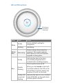
LED and Microphone
Microphone
(reserved for
future use)
Color State Status
White
Steady
Factory default, waiting for
integration.
Flashing
Initializing.
White/
Blue
Alternating
Device is busy; do not touch or
unplug it. This usually indicates
that a process such as a firmware
upgrade is taking place.
Blue
Steady
Indicates the device has been
successfully integrated into a
network and is working properly.
Quickly
Flashing
This is used to locate an AP.
When you click Locate in the UniFi
Controller software, the LED on the
AP will flash. It will also display the
location of the AP on the map.
Steady with
occasional
flashing
Indicates the device is in an isolated
state (all WLANs are brought down
until an uplink is found).

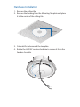
Hardware Installation
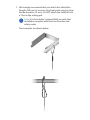
1. Remove the ceiling tile.
2. Remove the backing from the Mounting Template and place
it in the center of the ceiling tile.
242 mm
3. Cut or drill a hole around the template.
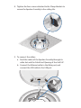
4. Rotate the UniFiAP counterclockwise to release it from the
Speaker Assembly.

5. Feed an Ethernet cable through the hole and connect it to
the Main port of the Speaker Assembly.
6. If necessary, lift and rotate the Clamp Brackets so they
remain elevated and tucked against the Speaker Assembly.
Insert the Speaker Assembly into the hole.

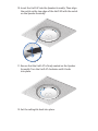
7. We strongly recommend that you attach the Safety Wire
(length: 430 mm) to a secure structural point using its clasp
(inside diameter: 14 mm). Do NOT attach the Safety Wire to
a T-bar in the ceiling grid.
Note: It is the installer’s responsibility to verify that
installation complies with local construction and
safety codes.
Two examples are shown below.

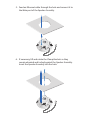
8. Tighten the four screws attached to the Clamp Brackets to
secure the Speaker Assembly to the ceiling tile.
9. To connect the cables:
a. Feed the cables of the Speaker Assembly through its
cable slot and the Cable Feed Opening of the UniFi AP.
b. Connect the Ethernet cable to the Main port, and
connect the USB cable to the USB port.

10. Insert the UniFi AP into the Speaker Assembly. Then align
the notch on the top edge of the UniFi AP with the notch
on the Speaker Assembly.
11. Ensure that the UniFi AP is firmly seated on the Speaker
Assembly. Turn the UniFi AP clockwise until it locks
intoplace.
12. Set the ceiling tile back into place.

Powering the UniFi AP
The UniFi AP AC EDU features auto-sensing 802.3at PoE+
support and can be powered by any of the following:
• Ubiquiti Networks UniFi Switch (recommended and sold
separately)
• 802.3at PoE+ compliant switch
• Ubiquiti Networks Gigabit PoE Adapter* (48V, 0.5A)
* Included only in the single-pack of the UAP-AC-EDU.
Connecting to a PoE+ Switch
Connect the Ethernet cable from the UniFi AP AC EDU directly
to a PoE port on the switch.
1 3 5 7 9 11 13 15 17 19 21 22
2 4 6 8 10 12 14 16 18 20 22 24
SFP1
SFP2
UniFi Switch Power Connection Diagram

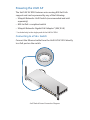
Connecting to a PoE Adapter
Note: The Gigabit PoE adapter is included only in the
single-pack of the UAP-AC-EDU.
1. Connect the Ethernet cable from the UniFi AP AC EDU to
the POE port of the Gigabit PoE adapter.
2. Connect an Ethernet cable from your LAN to the LAN port
of the Gigabit PoE adapter.
3. Connect the Power Cord to the adapter, and then plug the
Power Cord to a power outlet.
Mounting the PoE Adapter (Optional)
1. Remove the PoE Mounting Bracket from the adapter, place
the bracket at the desired location, and mark the two holes.
2. Pre-drill the holes if necessary, and secure the bracket
using two fasteners (not included).
3. Align the slots of the adapter with the tabs of the PoE
Mounting Bracket, and then slide the adapterdown.

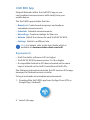
Controller Software Installation
Download and install the latest version of the UniFi Controller
software at: downloads.ubnt.com/unifi
Launch the software and follow the on-screen instructions.
Step-by-step instructions are available in the User Guide
located on our website: documentation.ubnt.com/unifi
After you have installed the software and run the UniFi
Installation Wizard, a login screen will appear for the UniFi
Controller management interface. Enter the Username and
Password that you created and click Login.
You can manage your wireless network and view network
statistics using the UniFi Controller management interface.
For information on configuring and using the UniFi Controller
software, refer to the User Guide available at:
documentation.ubnt.com/unifi
*640-00226-06*
640-00226-06

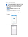
UniFi EDU App
Ubiquiti Networks offers the UniFi EDU app so you
can broadcast announcements with clarity from your
mobiledevice.
The UniFi EDU app includes five tabs:
• Broadcast Create broadcast groups and make an
immediate announcement.
• Schedule Schedule announcements.
• Recordings Create recordings for later use.
• Volume Adjust the volume for each UniFi AP AC EDU.
• Settings Switch to a different site.
Note: For details, refer to the User Guide, which is
available at: documentation.ubnt.com/unifi
Requirements
• UniFi Controller software v4.9.5 or higher
• UniFi AP AC EDU firmware version 3.4.18 or higher
• A compatible Android or iOS device located on the same
Layer-2 network as the UniFi Controller and UniFi APs
The following instructions describe the iOS version of the app;
however, the Android version is similar.
To log in and make an immediate announcement:
1. Download the UniFi EDU app from the AppStore (iOS) or
Google Play
™
(Android).
2. Launch the app.

3. Enter the following information:
• (IP address) Enter the IP address of the UniFi Controller.
Note: If you do not know the IP address, you can click
Find to detect a UniFi Controller and then select it.
• (port) Enter the appropriate port number, which is
typically 8443.
• (username) Enter your username for the UniFi
Controller.
• (password) Enter your password for the UniFi
Controller.
• Remember username and password Tap this option if
you want the app to remember your login.
Tap Connect.
4. To create a broadcast group, tap .

5. Enter a descriptive name in the Group Name field.
6. Tap the appropriate UniFi AC EDU APs and then tap Save.
7. Tap the broadcast group you want to use.
8. Tap Start broadcast to start the announcement.
9. Tap Stop broadcast to end the announcement.
The speakers will automatically be muted when you stop
broadcasting.

Specifications
UAP-AC-EDU
Dimensions 287.5 x 287.5 x 125.9 mm
(11.32 x 11.32 x 4.96")
Weight 1.820 kg (4.012 lb)
Networking Interface (2) 10/100/1000 Ethernet Ports
Port (1) USB Port
Buttons Reset
Power Method 803.2at PoE+
Power Supply 48V, 0.5A PoE Gigabit Adapter
1
Supported Voltage Range 44VDC to 57VDC
Max. Power Consumption 20W
Max. TX Power
2.4 GHz
5 GHz
22 dBm
22 dBm
MIMO
2.4 GHz
5 GHz
3 x 3
3 x 3
Throughput Speeds
2
2.4 GHz
5 GHz
450 Mbps
1300 Mbps
Range
2
122 m (400 ft)
Antennas (3) Dual-Band Internal
Antenna Gain 2.4 GHz: 3 dBi, 5 GHz: 3 dBi
Wi-Fi Standards 802.11 a/b/g/n/ac
Wireless Security WEP, WPA-PSK,
WPA Enterprise (WPA/WPA2, TKIP/AES)
BSSID Up to Four per Radio
Mounting Wall/Ceiling (Kits Included)
Operating Temperature -10 to 70° C (14 to 158° F)
Operating Humidity 5 - 95% Noncondensing
Certications CE, FCC, IC
1 Only the single-pack of the UAP-AC-EDU includes a PoE adapter.
2 Speed and Range values may vary and are based on optimal
environments.

Safety Notices
1. Read, follow, and keep these instructions.
2. Heed all warnings.
3. Only use attachments/accessories specified by the manufacturer.
WARNING: Do not use this product in location that can
be submerged by water.
WARNING: Avoid using this product during an electrical
storm. There may be a remote risk of electric shock from
lightning.
Electrical Safety Information
1. Compliance is required with respect to voltage, frequency, and current
requirements indicated on the manufacturer’s label. Connection to a
different power source than those specified may result in improper
operation, damage to the equipment or pose a fire hazard if the
limitations are not followed.
2. There are no operator serviceable parts inside this equipment. Service
should be provided only by a qualified service technician.
3. This equipment is provided with a detachable power cord which has
an integral safety ground wire intended for connection to a grounded
safety outlet.
a. Do not substitute the power cord with one that is not the provided
approved type. Never use an adapter plug to connect to a 2-wire
outlet as this will defeat the continuity of the grounding wire.
b. The equipment requires the use of the ground wire as a part of the
safety certification, modification or misuse can provide a shock
hazard that can result in serious injury or death.
c. Contact a qualified electrician or the manufacturer if there
are questions about the installation prior to connecting the
equipment.
d. Protective earthing is provided by Listed AC adapter. Building
installation shall provide appropriate short-circuit backup
protection.
e. Protective bonding must be installed in accordance with local
national wiring rules and regulations.

Limited Warranty
UBIQUITI NETWORKS, Inc (“UBIQUITI NETWORKS”) warrants that the
product(s) furnished hereunder (the “Product(s)”) shall be free from defects
in material and workmanship for a period of one (1) year from the date
of shipment by UBIQUITI NETWORKS under normal use and operation.
UBIQUITI NETWORKS’ sole and exclusive obligation and liability under
the foregoing warranty shall be for UBIQUITI NETWORKS, at its discretion,
to repair or replace any Product that fails to conform to the above
warranty during the above warranty period. The expense of removal and
reinstallation of any Product is not included in this warranty. The warranty
period of any repaired or replaced Product shall not extend beyond its
original term.
Warranty Conditions
The above warranty does not apply if the Product:
(I) has been modified and/or altered, or an addition made thereto,
except by Ubiquiti Networks, or Ubiquiti Networks’ authorized
representatives, or as approved by Ubiquiti Networks in writing;
(II) has been painted, rebranded or physically modified in any way;
(III) has been damaged due to errors or defects in cabling;
(IV) has been subjected to misuse, abuse, negligence, abnormal
physical, electromagnetic or electrical stress, including lightning
strikes, or accident;
(V) has been damaged or impaired as a result of using third party
firmware;
(VI) has no original Ubiquiti MAC label, or is missing any other original
Ubiquiti label(s); or
(VII) has not been received by Ubiquiti within 30 days of issuance of
the RMA.
In addition, the above warranty shall apply only if: the product has been
properly installed and used at all times in accordance, and in all material
respects, with the applicable Product documentation; all Ethernet cabling
runs use CAT5 (or above), and for outdoor installations, shielded Ethernet
cabling is used, and for indoor installations, indoor cabling requirements
are followed.
Returns
No Products will be accepted for replacement or repair without obtaining
a Return Materials Authorization (RMA) number from UBIQUITI NETWORKS
during the warranty period, and the Products being received at UBIQUITI
NETWORKS’ facility freight prepaid in accordance with the RMA process of
UBIQUITI NETWORKS. Products returned without an RMA number will not
be processed and will be returned freight collect or subject to disposal.
Information on the RMA process and obtaining an RMA number can be
found at: www.ubnt.com/support/warranty.
Pagina se încarcă ...
Pagina se încarcă ...
Pagina se încarcă ...
Pagina se încarcă ...
Pagina se încarcă ...
Pagina se încarcă ...
Pagina se încarcă ...
Pagina se încarcă ...
-
 1
1
-
 2
2
-
 3
3
-
 4
4
-
 5
5
-
 6
6
-
 7
7
-
 8
8
-
 9
9
-
 10
10
-
 11
11
-
 12
12
-
 13
13
-
 14
14
-
 15
15
-
 16
16
-
 17
17
-
 18
18
-
 19
19
-
 20
20
-
 21
21
-
 22
22
-
 23
23
-
 24
24
-
 25
25
-
 26
26
-
 27
27
-
 28
28


Ubiquiti UniFi Ghid de inițiere rapidă
- Categorie
- Antene de rețea
- Tip
- Ghid de inițiere rapidă
în alte limbi
- English: Ubiquiti UniFi Quick start guide
- italiano: Ubiquiti UniFi Guida Rapida
Lucrări conexe
-
Ubiquiti Networks UniFi Manualul utilizatorului
-
Ubiquiti UC-CK Ghid de inițiere rapidă
-
-
Ubiquiti Networks UAP-AC Manualul utilizatorului
-
-
Ubiquiti airRouter HP Ghid de inițiere rapidă
-
Ubiquiti Networks Réseau de points de UAP-AC-LITE-5 accès Manual de utilizare
-
-
-
Ubiquiti UAP-PRO Ghid de inițiere rapidă