Ubiquiti UniFI UAP-AC Ghid de inițiere rapidă
- Tip
- Ghid de inițiere rapidă

Enterprise WiFi System
Model: UAP-AC


1
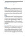
Introduction
Introduction
Thank you for purchasing the Ubiquiti Networks
™
UniFi
™
Enterprise
WiFi System. The UniFi Enterprise WiFi System includes the UniFi
Controller software, which allows you to manage your wireless
network using a web browser.
This Quick Start Guide includes the warranty terms and is for use
with the UniFi AP-AC, model UAP-AC. The UniFi Enterprise WiFi
System also includes the necessary hardware for mounting the
unit on a wall or a ceiling. The UniFi AP can be powered by any of
the following:
• PoE GigE Adapter (included)
• PoE+ 802.3at compliant switch
• Ubiquiti Networks TOUGHSwitch PRO, model TS-8-PRO
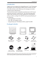
Package Contents
UniFi AP AC Mounting Bracket Ceiling Backing Plate
M3x50 Flat Head
Screws (Qty. 4)
M3 Keps Nuts
(Qty. 4)
M2.9x20 Screws
(Qty. 4)
M3x20 Screw
Anchors (Qty. 4)
Enterprise WiFi System
Model: UAP-AC
UniFi Controller
CD with User Guide
PoE GigE Adapter
(48V, 0.5A Gigabit)
Power Cord Quick Start Guide
TERMS OF USE: All Ethernet cabling runs must use CAT5 (or above). It is the customer’s responsibility to
follow local country regulations, including operation within legal frequency channels, output power,
indoor cabling requirements, and Dynamic Frequency Selection (DFS) requirements.

2
UniFi
™
AP-AC Quick Start Guide
System Requirements
• Microsoft Windows Vista, Windows 7, Windows 8, or Mac OS X
• Java Runtime Environment 1.6 (or above)
• Web Browser: Mozilla Firefox, Google Chrome, or Microsoft
Internet Explorer 8 (or above)
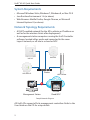
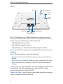
Network Topology Requirements
• A DHCP-enabled network (for the AP to obtain an IP address as
well as for the wireless clients after deployment)
• A management station computer running the UniFi Controller
software, located either onsite and connected to the same
Layer-2 network, or off-site in a cloud or NOC
or
Router
O-Site
Cloud/NOC
On-Site
Management Station
UAP-AC
UAP/UAP-LR
UAP-PRO
UAP-Outdoor
Sample Network Diagram
All UniFi APs support off-site management controllers. Refer to the
User Guide on the CD for setup details.

3
Hardware Overview
Hardware Overview
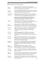
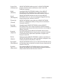
LED
LED Color Status
Flashing white Initializing.
Steady white Factory default, waiting to be integrated.
Alternating
white/blue
Device is busy; do not touch or unplug it.
This usually indicates that a process such as a
firmware upgrade is taking place.
Quickly flashing
blue
This is used to locate an AP.
When you click Locate in the UniFi Controller
software, the AP will flash. It will also display
the location of the AP on the map.
Steady blue Indicates the device has been successfully
integrated into a network and is working
properly.
Steady blue
with occasional
flashing
Indicates the device is in an isolated state (all
WLANs are brought down until an uplink is
found).

4
UniFi
™
AP-AC Quick Start Guide
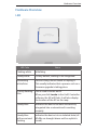
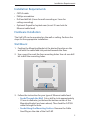
Ports
MAIN SECONDARY
Reset
This device complies with Part 15 of FCC rules.
Operation is subject to the following 2 conditions:
1) this device may not cause ha rmful interfe rence
and, 2) this device must ac cept any interfe rence
received, including interference that may cause
undesired operation.
FCC ID: SWX- UAPAC IC: 6545A-UAPAC
0560
M/N: UAP- AC 48V 0.5A POE
AP AC
|
Main Port
Secondary Port
Reset Button
Cable Feed Plug
Locking
Notch
Locking
Clip
Mounting Bracket
Main The Main port is a Gigabit Ethernet port used to connect
the power and should be connected to the LAN and DHCP server.
Power can be provided by any of the following:
• PoE GigE Adapter (included)
• PoE+ 802.3at compliant switch
• Ubiquiti Networks TOUGHSwitch PRO, model TS-8-PRO
Secondary The Secondary port is a Gigabit Ethernet port used for
bridging.
Reset The Reset button serves two functions:
• Restart It will restart the device when you press and release it
quickly.
• Restore Factory Defaults When you press and hold it for more
then 5 seconds, it will restore the device to the factory default
settings.
Locking Clip During installation, the Locking Clip on the Mounting
Bracket locks into the Locking Notch on the UniFi AP to help
prevent easy removal of the UniFi AP.
Cable Feed Plug If your Ethernet cable feeds along the mounting
surface, remove the Cable Feed Plug.

5
Installation Requirements
Installation Requirements
• CAT5/6 cable
• Phillips screwdriver
• Drill and drill bit (6 mm for wall-mounting or 3 mm for
ceiling-mounting)
• Optional: Drywall or keyhole saw (to cut 25 mm hole for
Ethernet cable feed)
Hardware Installation
The UniFi AP can be mounted on the wall or ceiling. Perform the
steps for the appropriate installation:
Wall Mount
1. Position the Mounting Bracket at the desired location on the
wall with the cable feed slot pointed towards the floor.
2. Use a pencil to mark the four mounting holes. Use a 6 mm drill
bit to drill the mounting holes.
Top
Optional 25 mm Hole for
Ethernet Cable Feed through Wall
3. Follow the instruction for your type of Ethernet cable feed:
- Feeds Through the Wall Cut or drill a circle approximately
25 mm in diameter, just below the bottom center of the
Mounting Bracket (as shown above). Then feed the CAT5/6
cable through the hole.
- Feeds Along the Mounting Surface Remove the Cable
Feed Plug on the side of the UniFi AP.

6
UniFi
™
AP-AC Quick Start Guide
4. Insert the M3x20 Screw Anchors into the 6 mm holes. Secure the
Mounting Bracket to the wall by inserting the M2.9x20 Screws
into the anchors.
5. Connect the Ethernet cable to the Main port. If the feed is
along the mounting surface, feed the cable through the Cable
Feed of the UniFi AP.
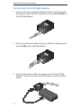
MAIN SECONDARY
RESET
This device complies with Part 15 of FCC rules.
Operation is subject to the following 2 conditions:
1) this device may not cause har mful interfere nce
and, 2) this device must acc ept any interfere nce
received, including interference that may cause
undesired operation.
FCC ID: SWX-U APAC IC: 6545A-UAPAC
0560
M/N: UAP-A C 48V 0.5A POE
AP AC
|

7
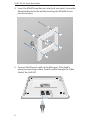
Hardware Installation
6. Align the slots on the UniFi AP with the tabs on the Mounting
Bracket.
7. Slide the UniFi AP down until it locks into place.

8
UniFi
™
AP-AC Quick Start Guide
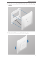
Ceiling Mount
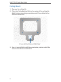
1. Remove the ceiling tile.
2. Place the Ceiling Backing Plate in the center of the ceiling tile.
Mark the four mounting screw holes and 25 mm hole for the
Ethernet cable feed.
25 mm Hole for Ethernet Cable Feed
3. Use a 3 mm drill bit to drill the screw holes, and cut or drill the
hole for the Ethernet cable feed.

9
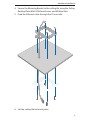
Hardware Installation
4. Secure the Mounting Bracket to the ceiling tile using the Ceiling
Backing Plate, M3x50 Flathead Screws, and M3 Keps Nuts.
5. Feed the Ethernet cable through the 25 mm hole.
6. Set the ceiling tile back into place.

10
UniFi
™
AP-AC Quick Start Guide
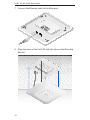
7. Connect the Ethernet cable to the Main port.
MAIN
SECONDARY
This device complies with Part 15 of FCC rules.
Operation is subject to the following 2 condit ions:
1) this device may not cause harmful inte rference
and, 2) this de vice must acce pt any interfe rence
receive d, includin g interfer ence that m ay cause
undes ired op eratio n.
FCC ID: SWX-U APAC IC: 65 45A -U APA C
056 0
M/N : UAP -AC 48V 0.5A POE
AP AC
|
8. Align the slots on the UniFi AP with the tabs on the Mounting
Bracket.

11
Powering the UniFi AP
9. Slide the UniFi AP down until it locks into place.
Powering the UniFi AP
The UniFi AP can be powered directly by a compatible PoE switch
or with the included PoE GigE Adapter.
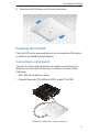
Connecting to a PoE Switch
Connect the other end of the Ethernet cable coming from the
Main port on the UniFi AP directly to a PoE port on one of the
following:
• PoE+ 802.3at compliant switch
• Ubiquiti Networks TOUGHSwitch PRO, model TS-8-PRO
TOUGHSwitch PRO Power Connection Diagram

12
UniFi
™
AP-AC Quick Start Guide
Connecting to the PoE GigE Adapter
1. Connect the other end of the Ethernet cable coming from the
Main port on the UniFi AP to the Ethernet port labeled POE on
the PoE GigE Adapter.
2. Connect an Ethernet cable from your LAN to the Ethernet port
labeled LAN on the PoE GigE Adapter.
3. Connect the power cord to the power port on the PoE GigE
Adapter. Connect the other end of the power cord to a power
outlet.

13
Software Installation
Software Installation
Insert the UniFi Controller software CD into your CD-ROM drive
and follow the instructions for your specific computer type.
Mac Users
1. Click the Install icon.
2. Click Continue and follow the on-screen instructions to install
the software.

14
UniFi
™
AP-AC Quick Start Guide
3. Go to Go > Applications and double-click the UniFi icon.
Proceed to Configuring the UniFi Controller Software on page 16.
PC Users
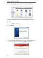
1. Launch UniFi-installer.exe.
2. Click Install.
3. If your computer doesn't have Java 1.6 or above installed, you
will be prompted to install it. Click Install to continue.

15
Software Installation
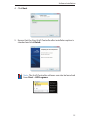
4. Click Next.
5. Ensure that the Start UniFi Controller after installation option is
checked and click Finish.
Note: The UniFi Controller software can also be launched
from Start > All Programs.

16
UniFi
™
AP-AC Quick Start Guide
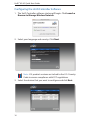
Configuring the UniFi Controller Software
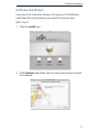
1. The UniFi Controller software startup will begin. Click Launch a
Browser to Manage Wireless Network.
2. Select your language and country. Click Next.
Note: U.S. product versions are locked to the U.S. Country
Code to ensure compliance with FCC regulations.
3. Select the devices that you want to configure and click Next.

17
Software Installation
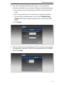
4. The UniFi Installation Wizard will create a secure primary
wireless network for your devices. Perform the following steps:
a. Enter the wireless network name (SSID) in the Secure SSID
field.
b. Enter a passphrase to be used for your primary network.
c. If you want to enable guest access, select Enable Guest
Access, and enter a guest network name in the Guest SSID
field.
d. Click Next.
5. Enter an admin name and password to use when accessing the
management interface. Confirm your password in the Confirm
field. Click Next.

18
UniFi
™
AP-AC Quick Start Guide
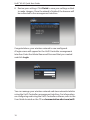
6. Review your settings. Click Finish to save your settings or Back
to make changes. Once the wizard is finished, the browser will
be redirected to the management interface.
Congratulations, your wireless network is now configured.
A login screen will appear for the UniFi Controller management
interface. Enter the Admin Name and Password that you created
and click Login.
You can manage your wireless network and view network statistics
using the UniFi Controller management interface. For information
on configuring and using the UniFi Controller software, refer to the
User Guide located on the CD or documentation.ubnt.com/unifi
Pagina se încarcă...
Pagina se încarcă...
Pagina se încarcă...
Pagina se încarcă...
Pagina se încarcă...
Pagina se încarcă...
Pagina se încarcă...
Pagina se încarcă...
Pagina se încarcă...
Pagina se încarcă...
Pagina se încarcă...
Pagina se încarcă...
-
 1
1
-
 2
2
-
 3
3
-
 4
4
-
 5
5
-
 6
6
-
 7
7
-
 8
8
-
 9
9
-
 10
10
-
 11
11
-
 12
12
-
 13
13
-
 14
14
-
 15
15
-
 16
16
-
 17
17
-
 18
18
-
 19
19
-
 20
20
-
 21
21
-
 22
22
-
 23
23
-
 24
24
-
 25
25
-
 26
26
-
 27
27
-
 28
28
-
 29
29
-
 30
30
-
 31
31
-
 32
32


Ubiquiti UniFI UAP-AC Ghid de inițiere rapidă
- Tip
- Ghid de inițiere rapidă
în alte limbi
- English: Ubiquiti UniFI UAP-AC Quick start guide
- italiano: Ubiquiti UniFI UAP-AC Guida Rapida
Lucrări înrudite
-
Ubiquiti UAP-Outdoor Ghid de inițiere rapidă
-
Ubiquiti Networks UAP-AC Manualul utilizatorului
-
-
Ubiquiti airRouter HP Ghid de inițiere rapidă
-
Ubiquiti UAP-PRO Ghid de inițiere rapidă
-
-
Ubiquiti UniFi Ghid de inițiere rapidă
-
-
Ubiquiti Networks UniFi Manualul utilizatorului
-