Ubiquiti Networks Réseau de points de UAP-AC-LITE-5 accès Manual de utilizare
- Tip
- Manual de utilizare

802.11ac Dual Radio
Access Point
Model: UAP-AC-LITE

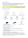
Introduction
Thank you for purchasing the Ubiquiti Networks® UniFi®AP.
This Quick Start Guide is designed to guide you through
installation and includes warranty terms.
IMPORTANT:
The UAP-AC-LITE requires the UniFi Controller
v5.4 or newer, available at: downloads.ubnt.com/unifi
Package Contents
UniFi AP AC Lite Mounting Bracket Ceiling Backing Plate
Flat Head Screws
(Qty. 4)
Keps Nuts
(Qty. 4)
Screws
(Qty. 4)
Screw Anchors
(Qty. 4)
802.11ac Dual Radio
Access Point
Model: UAP-AC-LITE
Gigabit PoE (24V, 0.5A)
with Mounting Bracket
Power Cord* Quick Start Guide
Installation Requirements
• Phillips screwdriver
• Drill and drill bit (6 mm for wall-mounting or 3 mm for
ceiling-mounting)
• Optional: Drywall or keyhole saw (to cut 18 mm hole for
Ethernet cable feed)
• Cat5/6 UTP cable for indoor installations
TERMS OF USE: Ubiquiti radio devices must be professionally installed. Shielded Ethernet
cable and earth grounding must be used as conditions of product warranty. TOUGHCable
™
is
designed for outdoor installations. It is the professional installer’s responsibility to follow local
country regulations, including operation within legal frequency channels, output power, and
Dynamic Frequency Selection (DFS) requirements.

System Requirements
• Linux, MacOSX, or Microsoft Windows 7/8/10
• Java Runtime Environment 1.8 (or above)
• Web Browser: Google Chrome (Other browsers may have
limited functionality).
• UniFi Controller software v5.4 or newer (available at:
www.ubnt.com/download/unifi)
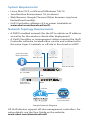
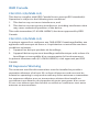
Network Topology Requirements
• A DHCP-enabled network (for the AP to obtain an IP address
as well as for the wireless clients after deployment)
• A UniFi Cloud Key or management station running the UniFi
Controller software, located either on-site and connected to
the same Layer-2 network, or off-site in the cloud or a NOC
US-16-150W
USG-PRO-4
(DHCP Server)
Internet
UAP-AC-Lite
UAP-AC-M-PRO
UAP-AC-HD
LAN
WAN
UniFi Cloud Key
(UniFi Controller)
Remote Access too
UniFi Controllerr
Sample Network Diagram
All UniFi devices support off-site management controllers. For
setup details, see the User Guide on the website:
www.ubnt.com/download/unifi

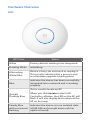
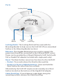
Hardware Overview
LED
LED Color Status
White
Factory default, waiting to be integrated.
Flashing White
Initializing.
Alternating
White/Blue
Device is busy; do not touch or unplug it.
This usually indicates that a process such
as a firmware upgrade is taking place.
Blue
Indicates the device has been successfully
integrated into a network and is working
properly.
Quickly
Flashing Blue
This is used to locate an AP.
When you click Locate in the UniFi
Controller software, the LED on the AP will
flash. It will also display the location of the
AP on the map.
Steady Blue
with occasional
flashing
Indicates the device is in an isolated state
(all WLANs are brought down until an
uplink is found).

Ports
Ethernet
Port
Reset
Button
Locking Notch
Cable
Feed Plug
Locking Notch The Locking Notch will be used with the
Mounting Bracket to help secure the UniFi AP. (This is described
further in the Mounting Bracket section.)
Ethernet This Gigabit Ethernet port is used to connect the
power and should be connected to the LAN and DHCP server.
Power can be provided by a Ubiquiti Networks UniFi Switch with
PoE or Gigabit PoE adapter (included with single-pack only).
Reset The Reset button serves two functions for the UniFi AP:
• Restart Press and release the Reset button quickly.
• Restore to Factory Default Settings Press and hold the
Reset button for more than five seconds.
Alternatively, the UniFi AP may be reset remotely via a Reset
button located on the bottom of the Gigabit PoE adapter.
Cable Feed Plug If your Ethernet cable feeds along the
mounting surface, remove the Cable Feed Plug.

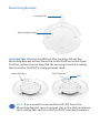
Mounting Bracket
Mounting Bracket
Locking Tab
Locking Tab During installation, the Locking Tab on the
Mounting Bracket moves from the Initial Position to the Final
Position, where the Locking Tab fits securely into the Locking
Notch on the UniFi AP to help prevent theft.
Initial Position Final Position
Slot
Note:
If you need to remove the UniFi AP from the
Mounting Bracket, insert a paper clip in the Slot to release
the Locking Tab and turn the UniFi AP counterclockwise.

Hardware Installation
The UniFi AP can be mounted on the wall or ceiling. Perform
the steps for the appropriate installation:
Wall Mount
1. Position the Mounting Bracket at the desired location on
the wall with the arrow pointing up.
2. Use a pencil to mark the four mounting holes. Use a 6 mm
drill bit to drill the mounting holes.
Arrow
3. If your Ethernet cable feeds through the wall, then cut or
drill a circle approximately 18 mm in diameter. Then feed
the CAT5/6 cable through the hole.
25 mm
Note: 25 mm is the distance from the center of the
bottom mounting hole to the center of the cable hole.

4. Insert the Screw Anchors into the 6 mm holes. Secure the
Mounting Bracket to the wall by inserting the Screws into
the anchors.
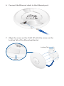
5. If the Ethernet cable runs along the mounting surface,
remove the Cable Feed Plug.

6. Connect the Ethernet cable to the Ethernet port.
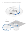
7. Align the arrow on the UniFi AP with the arrow on the
Locking Tab of the Mounting Bracket.
Arrow
Locking Tab

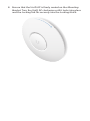
8. Ensure that the UniFi AP is firmly seated on the Mounting
Bracket. Turn the UniFi AP clockwise until it locks into place
and the Locking Tab fits securely into the Locking Notch.

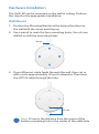
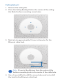
Ceiling Mount
1. Remove the ceiling tile.
2. Place the Ceiling Backing Plate in the center of the ceiling
tile. Mark the four mounting screw holes.
3. Mark a hole approximately 18 mm in diameter for the
Ethernet cable feed.
25 mm
Note: 25 mm is the distance from the center of the
bottom mounting hole to the center of the cable hole.
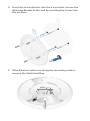
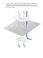
4. Use a 3 mm drill bit to drill the screw holes, and cut or drill
the hole for the Ethernet cable feed.

5. Insert the Flat Head Screws through the Mounting Bracket,
ceiling tile, and Ceiling Backing Plate. Fasten the screws
using the Keps Nuts. Then feed the Ethernet cable through
the 18 mm hole.

6. Connect the Ethernet cable to the Ethernet port.
7. Align the arrow on the UniFi AP with the arrow on the
Locking Tab of the Mounting Bracket.
Locking Tab
Arrow

8. Ensure that the UniFi AP is firmly seated on the Mounting
Bracket. Turn the UniFi AP clockwise until it locks into place
and the Locking Tab fits securely into the Locking Notch.
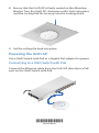
9. Set the ceiling tile back into place.
Powering the UniFi AP
Use a UniFi Switch with PoE or a Gigabit PoE adapter for power.
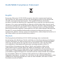
Connecting to a UniFi Switch with PoE
Connect the Ethernet cable from the UniFi AP directly to a PoE
port on the UniFi Switch with PoE.
1 3 5 7 9 11 13 15 17 19 21 22
2 4 6 8 10 12 14 16 18 20 22 24
SPF1
SPF2
*640-00180-08*
640-00180-08

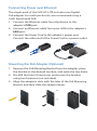
Connecting Power over Ethernet
The single-pack of the UAP-AC-LITE includes one Gigabit
PoE adapter. For multi-pack units, we recommend using a
UniFiSwitch with PoE.
1. Connect the Ethernet cable from the device to the
adapter’s POE port.
2. Connect an Ethernet cable from your LAN to the adapter’s
LAN port.
3. Connect the Power Cord to the adapter’s power port.
Connect the other end of the Power Cord to a power outlet.
Mounting the PoE Adapter (Optional)
1. Remove the PoE Mounting Bracket from the adapter, place
the bracket at the desired location, and mark the two holes.
2. Pre-drill the holes if necessary, and secure the bracket
using two fasteners (not included).
3. Align the adapter’s slots with the tabs of the PoE Mounting
Bracket, and then slide the adapterdown.

Software Installation
Download and install the latest version of the UniFi Controller
software. Launch it and follow the on-screen instructions. The
software and step-by-step instructions in the User Guide are
available at: www.ubnt.com/download/unifi
After you have installed the software and run the UniFi
Installation Wizard, a login screen will appear for the UniFi
Controller management interface. Enter the Admin Name and
Password that you created and click Log In..
You can manage your wireless network and view network
statistics using the UniFi Controller management interface.
For information on configuring and using the UniFi Controller
software, refer to the User Guide.
Mobile App Installation
Ubiquiti Networks also offers the UniFi mobile app, which
is available from the App Store (iOS) or Google Play
™
Store
(Android). You can use it to provision a UniFi AP for basic
functionality without configuring a UniFi Controller. It also
allows seamless provisioning of APs for remote controllers
(controllers not on the same Layer 2 network) and easy access
to local controllers and those monitored on unifi.ubnt.com

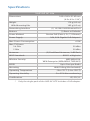
Specifications
UniFi AP AC Lite
Dimensions 160 x 160 x 31.45 mm
(6.3 x 6.3 x 1.24")
Weight
With Mounting Kits
170 g (6.0 oz)
185 g (6.5 oz)
Networking Interface (1) 10/100/1000 Ethernet Port
Buttons (1) Reset to Defaults
Power Method Passive PoE (Pairs 4, 5+; 7, 8 Return)
Power Supply 24V, 0.5A Gigabit PoE Adapter*
Max. Power Consumption 6.5W
Max. TX Power
2.4 GHz
5 GHz
20 dBm
20 dBm
Antennas (2) Dual-Band Antennas, 3 dBi Each
Wi-Fi Standards 802.11 a/b/g/n/ac
Wireless Security WEP, WPA-PSK,
WPA-Enterprise (WPA/WPA2, TKIP/AES)
BSSID Up to Four per Radio
Mounting Wall/Ceiling (Kits Included)
Operating Temperature -10 to 70° C (14 to 158° F)
Operating Humidity 5 to 95% Noncondensing
Certications CE, FCC, IC
* Only the single-pack of the UAP-AC-LITE includes a PoE adapter.

Safety Notices
1. Read, follow, and keep these instructions.
2. Heed all warnings.
3. Only use attachments/accessories specified by the manufacturer.
WARNING: Do not use this product in location that can
be submerged by water.
WARNING: Avoid using this product during an electrical
storm. There may be a remote risk of electric shock from
lightning.
Electrical Safety Information
1. Compliance is required with respect to voltage, frequency, and current
requirements indicated on the manufacturer’s label. Connection to a
different power source than those specified may result in improper
operation, damage to the equipment or pose a fire hazard if the
limitations are not followed.
2. There are no operator serviceable parts inside this equipment. Service
should be provided only by a qualified service technician.
3. This equipment is provided with a detachable power cord which has
an integral safety ground wire intended for connection to a grounded
safety outlet.
a. Do not substitute the power cord with one that is not the provided
approved type. Never use an adapter plug to connect to a 2-wire
outlet as this will defeat the continuity of the grounding wire.
b. The equipment requires the use of the ground wire as a part of the
safety certification, modification or misuse can provide a shock
hazard that can result in serious injury or death.
c. Contact a qualified electrician or the manufacturer if there
are questions about the installation prior to connecting the
equipment.
d. Protective earthing is provided by Listed AC adapter. Building
installation shall provide appropriate short-circuit backup
protection.
e. Protective bonding must be installed in accordance with local
national wiring rules and regulations.

Limited Warranty
UBIQUITI NETWORKS, Inc (“UBIQUITI NETWORKS”) warrants that the
product(s) furnished hereunder (the “Product(s)”) shall be free from defects
in material and workmanship for a period of one (1) year from the date
of shipment by UBIQUITI NETWORKS under normal use and operation.
UBIQUITI NETWORKS’ sole and exclusive obligation and liability under
the foregoing warranty shall be for UBIQUITI NETWORKS, at its discretion,
to repair or replace any Product that fails to conform to the above
warranty during the above warranty period. The expense of removal and
reinstallation of any Product is not included in this warranty. The warranty
period of any repaired or replaced Product shall not extend beyond its
original term.
Warranty Conditions
The above warranty does not apply if the Product:
(I) has been modified and/or altered, or an addition made thereto,
except by Ubiquiti Networks, or Ubiquiti Networks’ authorized
representatives, or as approved by Ubiquiti Networks in writing;
(II) has been painted, rebranded or physically modified in any way;
(III) has been damaged due to errors or defects in cabling;
(IV) has been subjected to misuse, abuse, negligence, abnormal
physical, electromagnetic or electrical stress, including lightning
strikes, or accident;
(V) has been damaged or impaired as a result of using third party
firmware;
(VI) has no original Ubiquiti MAC label, or is missing any other original
Ubiquiti label(s); or
(VII) has not been received by Ubiquiti within 30 days of issuance of
the RMA.
In addition, the above warranty shall apply only if: the product has been
properly installed and used at all times in accordance, and in all material
respects, with the applicable Product documentation; all Ethernet cabling
runs use CAT5 (or above), and for outdoor installations, shielded Ethernet
cabling is used, and for indoor installations, indoor cabling requirements
are followed.
Returns
No Products will be accepted for replacement or repair without obtaining
a Return Materials Authorization (RMA) number from UBIQUITI NETWORKS
during the warranty period, and the Products being received at UBIQUITI
NETWORKS’ facility freight prepaid in accordance with the RMA process of
UBIQUITI NETWORKS. Products returned without an RMA number will not
be processed and will be returned freight collect or subject to disposal.
Information on the RMA process and obtaining an RMA number can be
found at: www.ubnt.com/support/warranty

Disclaimer
EXCEPT FOR ANY EXPRESS WARRANTIES PROVIDED HEREIN, UBIQUITI
NETWORKS, ITS AFFILIATES, AND ITS AND THEIR THIRD PARTY DATA,
SERVICE, SOFTWARE AND HARDWARE PROVIDERS HEREBY DISCLAIM
AND MAKE NO OTHER REPRESENTATION OR WARRANTY OF ANY KIND,
EXPRESS, IMPLIED OR STATUTORY, INCLUDING, BUT NOT LIMITED TO,
REPRESENTATIONS, GUARANTEES, OR WARRANTIES OF MERCHANTABILITY,
ACCURACY, QUALITY OF SERVICE OR RESULTS, AVAILABILITY,
SATISFACTORY QUALITY, LACK OF VIRUSES, QUIET ENJOYMENT, FITNESS
FOR A PARTICULAR PURPOSE AND NON-INFRINGEMENT AND ANY
WARRANTIES ARISING FROM ANY COURSE OF DEALING, USAGE OR
TRADE PRACTICE IN CONNECTION WITH SUCH PRODUCTS AND SERVICES.
BUYER ACKNOWLEDGES THAT NEITHER UBIQUITI NETWORKS NOR
ITS THIRD PARTY PROVIDERS CONTROL BUYER’S EQUIPMENT OR THE
TRANSFER OF DATA OVER COMMUNICATIONS FACILITIES, INCLUDING
THE INTERNET, AND THAT THE PRODUCTS AND SERVICES MAY BE
SUBJECT TO LIMITATIONS, INTERRUPTIONS, DELAYS, CANCELLATIONS
AND OTHER PROBLEMS INHERENT IN THE USE OF COMMUNICATIONS
FACILITIES. UBIQUITI NETWORKS, ITS AFFILIATES AND ITS AND THEIR THIRD
PARTY PROVIDERS ARE NOT RESPONSIBLE FOR ANY INTERRUPTIONS,
DELAYS, CANCELLATIONS, DELIVERY FAILURES, DATA LOSS, CONTENT
CORRUPTION, PACKET LOSS, OR OTHER DAMAGE RESULTING FROM ANY
OF THE FOREGOING. In addition, UBIQUITI NETWORKS does not warrant
that the operation of the Products will be error-free or that operation will
be uninterrupted. In no event shall UBIQUITI NETWORKS be responsible
for damages or claims of any nature or description relating to system
performance, including coverage, buyer’s selection of products (including
the Products) for buyer’s application and/or failure of products (including
the Products) to meet government or regulatory requirements.
Limitation of Liability
EXCEPT TO THE EXTENT PROHIBITED BY LOCAL LAW, IN NO EVENT WILL
UBIQUITI OR ITS SUBSIDIARIES, AFFILIATES OR SUPPLIERS BE LIABLE FOR
DIRECT, SPECIAL, INCIDENTAL, CONSEQUENTIAL OR OTHER DAMAGES
(INCLUDING LOST PROFIT, LOST DATA, OR DOWNTIME COSTS), ARISING
OUT OF THE USE, INABILITY TO USE, OR THE RESULTS OF USE OF THE
PRODUCT, WHETHER BASED IN WARRANTY, CONTRACT, TORT OR OTHER
LEGAL THEORY, AND WHETHER OR NOT ADVISED OF THE POSSIBILITY OF
SUCH DAMAGES.
Pagina se încarcă...
Pagina se încarcă...
Pagina se încarcă...
Pagina se încarcă...
Pagina se încarcă...
Pagina se încarcă...
Pagina se încarcă...
Pagina se încarcă...
-
 1
1
-
 2
2
-
 3
3
-
 4
4
-
 5
5
-
 6
6
-
 7
7
-
 8
8
-
 9
9
-
 10
10
-
 11
11
-
 12
12
-
 13
13
-
 14
14
-
 15
15
-
 16
16
-
 17
17
-
 18
18
-
 19
19
-
 20
20
-
 21
21
-
 22
22
-
 23
23
-
 24
24
-
 25
25
-
 26
26
-
 27
27
-
 28
28


Ubiquiti Networks Réseau de points de UAP-AC-LITE-5 accès Manual de utilizare
- Tip
- Manual de utilizare
în alte limbi
Lucrări înrudite
-
Ubiquiti Networks UniFi Manualul utilizatorului
-
Ubiquiti Networks UAP-AC-M Manualul utilizatorului
-
-
-
Ubiquiti Networks UAP-AC Manualul utilizatorului
-
Ubiquiti Networks UT-Phone-Touch Manualul utilizatorului
Alte documente
-
Ubiquiti UniFi nanoHD UAP-nanoHD Ghid de inițiere rapidă
-
-
Ubiquiti UAP-PRO Ghid de inițiere rapidă
-
-
-
-
-
Ubiquiti UniFi Ghid de inițiere rapidă
-
Ubiquiti UAP-nanoHD Compact 802.11ac Wave 2 Enterprise Access Point Manualul utilizatorului
-
Ubiquiti UCK-G2 Ghid de inițiere rapidă