Ubiquiti UAP-AC-SHD-5 Ghid de inițiere rapidă
- Tip
- Ghid de inițiere rapidă

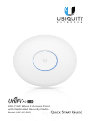
802.11AC Wave 2 Access Point
with Dedicated Security Radio
Model: UAP-AC-SHD

Introduction
Thank you for purchasing the Ubiquiti Networks®
UniFi®802.11AC Wave 2 Access Point with Dedicated Security
Radio. This Quick Start Guide is designed to guide you through
installation and includes warranty terms.
IMPORTANT: The UAP-AC-SHD requires the UniFi Controller
v5.4 or newer, available at: downloads.ubnt.com/unifi
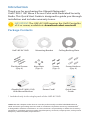
Package Contents
UniFi AP AC SHD Mounting Bracket Ceiling Backing Plate
Flat Head Screws
(Qty. 4)
Keps Nuts
(Qty. 4)
Screws
(Qty. 4)
Screw Anchors
(Qty. 4)
802.11AC Wave 2 Access Point
with Dedicated Security Radio
Model: UAP-AC-SHD
Gigabit PoE* (48V, 0.5A)
with Mount Bracket
Power Cord* Quick Start
Guide
* Included only in the single-pack of the UAP-AC-SHD
TERMS OF USE: Ubiquiti radio devices must be professionally installed. Shielded Ethernet
cable and earth grounding must be used as conditions of product warranty. TOUGHCable™
is designed for outdoor installations. It is the customer’s responsibility to follow local country
regulations, including operation within legal frequency channels, output power, and Dynamic
Frequency Selection (DFS) requirements.

Installation Requirements
• Phillips screwdriver
• Drill and drill bit (6 mm for wall-mounting or 3 mm for
ceiling-mounting)
• Optional: Drywall or keyhole saw (to cut 18 mm hole for
Ethernet cable feed)
• Cat5/6 UTP cable for indoor installations
Outdoor Installation Requirements
IMPORTANT: The UAP-AC-SHD may be installed
outdoors under an eave or other protected location. Do
not install the UniFi AP in an open environment.
• Mounting location should be at least 60 cm (2 ft) from the
edge of the eave or ceiling.
• Cable feed opening must be directed away from the open
environment.
• Cable feed must be pointed downwards when wall-mounted.
• Shielded Category 5 (or above) cabling should be used
for all outdoor wired Ethernet connections and should be
grounded through the AC ground of the PoE.
We recommend that you protect your networks from
harmful outdoor environments and destructive ESD events
with industrial-grade, shielded Ethernet cable from Ubiquiti
Networks. For more details, visit:
www.ubnt.com/toughcable
System Requirements
• Linux, MacOSX, or Microsoft Windows 7/8/10
• Java Runtime Environment 1.6 (1.8 or newer recommended)
• Web Browser: Google Chrome (Other browsers may have
limited functionality.)
• UniFi Controller software v5.4 or newer (available at:
downloads.ubnt.com/unifi)

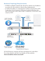
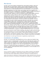
Network Topology Requirements
• A DHCP-enabled network (for the AP to obtain an IP address
as well as for the wireless clients after deployment)
• A UniFi Cloud Key or management station running the UniFi
Controller v5.4 (or newer) software, located either on-site
and connected to the same Layer 2 network, or off-site in the
cloud or NOC
US-16-150W
USG-PRO-4
(DHCP Server)
Internet
UAP-AC-SHD
UAP-AC-M-PRO
UAP-AC-PRO
LAN
WAN
UniFi Cloud Key
(UniFi Controller)
Remote Access to
UniFi Controller
Sample Network Diagram
All UniFi devices support off-site management controllers.
For setup details, see the User Guide on the website:
documentation.ubnt.com/unifi

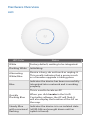
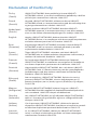
Hardware Overview
LED
LED Color Status
White Factory default, waiting to be integrated.
Flashing White Initializing.
Alternating
White/Blue
Device is busy; do not touch or unplug it.
This usually indicates that a process such
as a firmware upgrade is taking place.
Blue
Indicates the device has been successfully
integrated into a network and is working
properly.
Quickly
Flashing Blue
This is used to locate an AP.
When you click Locate in the UniFi
Controller software, the AP will flash. It
will also display the location of the AP on
the map.
Steady Blue
with occasional
flashing
Indicates the device is in an isolated state
(all WLANs are brought down until an
uplink is found).

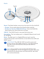
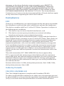
Ports
Main
Port
Secondary
Port
Security
Slot
Reset
Button
USB 3C
Port
Reset The Reset button serves two functions for the UniFi AP:
• Restart Press and release the Reset button quickly.
• Restore to Factory Default Settings Press and hold the
Reset button for more than five seconds.
USB 3C The USB 3C port is reserved for future use.
Secondary The Secondary port is a Gigabit Ethernet port used
for bridging.
Main The Main port is a Gigabit Ethernet port used to
connect the power and should be connected to the LAN and
DHCPserver.
IMPORTANT: The UAP-AC-SHD cannot be powered
by the US-8 or US-8-60W; however, it can be powered
by other UniFi PoE Switches that provide 802.3at
PoE+power.
Note: If you need to remove the UniFi AP from the
Mounting Bracket, insert a straightened paper clip in the
Security Slot to release the Lock Tab and turn the UniFi
AP counterclockwise.

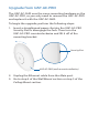
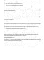
Upgrade from UAP-AC-PRO
The UAP-AC-SHD uses the same mounting hardware as the
UAP-AC-PRO, so you only need to remove the UAP-AC-PRO
and replace it with the UAP-AC-SHD.
To begin the upgrade, perform the following steps:
1. Insert a straightened paper clip into the UAP-AC-PRO
Security Slot to disengage the lock. Then turn the
UAP-AC-PRO counterclockwise and lift it off of the
mounting bracket.
Security Slot
UAP-AC-PRO (wall mount installation)
2. Unplug the Ethernet cable from the Main port.
3. Go to step 4 of the Wall Mount section or step 5 of the
Ceiling Mount section.

Hardware Installation
The UniFi AP can be mounted on the wall or ceiling. Perform
the steps for the appropriate installation:
Wall Mount
1. Position the Mounting Bracket at the desired location on
the wall with the Arrow pointing up.
2. Mark the four mounting holes, and use a 6 mm drill bit to
drill the holes. If your Ethernet cable feeds through the
wall, cut or drill a circle approximately 18 mm in diameter.
Then feed the CAT5/6 cable through the hole.
Arrow
Optional 18 mm Hole for
Ethernet Cable Feed through the Wall

3. Insert the Screw Anchors into the holes. Secure the
Mounting Bracket to the wall by inserting the Screws into
the anchors.
4. Remove the rubber port cover from the UniFi AP.

5. If the Ethernet cable is fed through the wall, skip to step6.
If the Ethernet cable runs along the mounting surface,
remove the cable feed plug.
6. Feed the Ethernet cable through the port cover.
Note: The feed hole will stretch to accommodate the
RJ45 connector, and then seal around the cable.
7. Connect the Ethernet cable to the Main port and replace
the port cover.

8. Align the Arrow on the top edge of the UniFi AP with the
Arrow on the Mounting Bracket.
Lock
Tab
Arrow
Arrow
9. Rotate the UniFi AP clockwise until the tabs lock into place
and the Lock Tab engages.

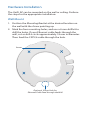
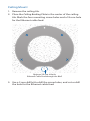
Ceiling Mount
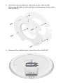
1. Remove the ceiling tile.
2. Place the Ceiling Backing Plate in the center of the ceiling
tile. Mark the four mounting screw holes and a 18 mm hole
for the Ethernet cable feed.
Optional 18 mm Hole for
Ethernet Cable Feed through the Wall
3. Use a 3 mm drill bit to drill the screw holes, and cut or drill
the hole for the Ethernet cable feed.

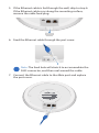
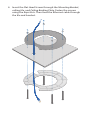
4. Insert the Flat Head Screws through the Mounting Bracket,
ceiling tile, and Ceiling Backing Plate. Fasten the screws
using the Keps Nuts. Then feed the Ethernet cable through
the tile and bracket.

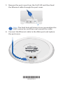
5. Remove the port cover from the UniFi AP, and then feed
the Ethernet cable through the port cover.
Note: The feed hole will stretch to accommodate the
RJ45 connector, and then seal around the cable.
6. Connect the Ethernet cable to the Main port and replace
the port cover.
*640-00279-01*
640-00279-01

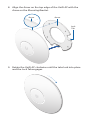
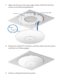
7. Align the Arrow on the top edge of the UniFi AP with the
Arrow on the Mounting Bracket.
Lock Tab
Arrow
Arrow
8. Rotate the UniFi AP clockwise until the tabs lock into place
and the Lock Tab engages.
9. Set the ceiling tile back into place.

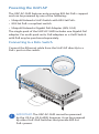
Powering the UniFi AP
The UAP-AC-SHD features auto-sensing 802.3at PoE+ support
and can be powered by one of the following:
• Ubiquiti Networks UniFi Switch with 802.3at PoE+
• 802.3at PoE+ compliant switch
• Ubiquiti Networks Gigabit PoE Adapter (48V, 0.5A)
The single-pack of the UAP-AC-SHD includes one Gigabit PoE
adapter. For multi-pack units, PoE adapters or a UniFi Switch
with PoE may be purchased separately.
Connecting to a PoE+ Switch
Connect the Ethernet cable from the UniFiAP directly to a
PoE+ port on the switch.
IMPORTANT: The UAP-AC-SHD cannot be powered
by the US-8 or US-8-60W; however, it can be powered
by other UniFi PoE Switches that provide 802.3at
PoE+power.

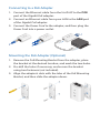
Connecting to a PoE Adapter
1. Connect the Ethernet cable from the UniFi AP to the POE
port of the Gigabit PoE adapter.
2. Connect an Ethernet cable from your LAN to the LAN port
of the Gigabit PoE adapter.
3. Connect the Power Cord to the adapter, and then plug the
Power Cord into a power outlet.
Mounting the PoE Adapter (Optional)
1. Remove the PoE Mounting Bracket from the adapter, place
the bracket at the desired location, and mark the two holes.
2. Pre-drill the holes if necessary, and secure the bracket
using two fasteners (not included).
3. Align the adapter’s slots with the tabs of the PoE Mounting
Bracket, and then slide the adapterdown.

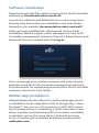
Software Installation
Download and install the latest version of the UniFi Controller
software at: downloads.ubnt.com/unifi
Launch the software and follow the on-screen instructions.
Step-by-step instructions are available in the User Guide
located on our website: documentation.ubnt.com/unifi
After you have installed the software and run the UniFi
Installation Wizard, a login screen will appear for the UniFi
Controller management interface. Enter the Admin Name and
Password that you created and click Log In.
You can manage your wireless network and view network
statistics using the UniFi Controller management interface.
For information on configuring and using the UniFi Controller
software, refer to the User Guide.
Mobile App Installation
Ubiquiti Networks also offers the UniFi mobile app, which
is available from the App Store (iOS) or Google Play™ Store
(Android™). You can use it to provision a UniFi AP for basic
functionality without configuring a UniFi Controller. It also
allows seamless provisioning of APs for remote controllers
(controllers not on the same Layer 2 network) and easy
access to both local controllers and those monitored on
unifi.ubnt.com.

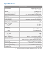
Specifications
UAP-AC-SHD
Dimensions 220 x 220 x 48.1 mm
(8.66 x 8.66 x 1.89")
Weight
with Mounting Kit
700 g (1.54 lb)
830 g (1.83 lb)
Networking Interface (2) 10/100/1000 Ethernet Ports
Buttons Reset
Power Method PoE+ 802.3at
Power Supply 48V, 0.5A Gigabit PoE Adapter*
Max. Power Consumption 17W
Max. TX Power
2.4 GHz
5 GHz
25 dBm
25 dBm
Antennas
2.4 GHz
5 GHz
(2) Dual-Polarity
(2) Dual-Polarity
Antenna Gain
2.4 GHz
5 GHz
3 dBi
4 dBi
Wi-Fi Standards 802.11 a/b/g/n/ac/ac-wave2
Wireless Security WEP, WPA-PSK,
WPA-Enterprise (WPA/WPA2, TKIP/AES)
Mounting Wall/Ceiling (Kits Included)
Operating Temperature -10 to 70° C (14 to 158° F)
Operating Humidity 5 to 95% Noncondensing
Certications CE, FCC, IC
* Included with the single-pack of the UAP-AC-SHD

Safety Notices
1. Read, follow, and keep these instructions.
2. Heed all warnings.
3. Only use attachments/accessories specified by the manufacturer.
WARNING: Do not use this product in location that can
be submerged by water.
WARNING: Avoid using this product during an electrical
storm. There may be a remote risk of electric shock from
lightning.
Electrical Safety Information
1. Compliance is required with respect to voltage, frequency, and current
requirements indicated on the manufacturer’s label. Connection to a
different power source than those specified may result in improper
operation, damage to the equipment or pose a fire hazard if the
limitations are not followed.
2. There are no operator serviceable parts inside this equipment. Service
should be provided only by a qualified service technician.
3. This equipment is provided with a detachable power cord which has
an integral safety ground wire intended for connection to a grounded
safety outlet.
a. Do not substitute the power cord with one that is not the provided
approved type. Never use an adapter plug to connect to a 2-wire
outlet as this will defeat the continuity of the grounding wire.
b. The equipment requires the use of the ground wire as a part of the
safety certification, modification or misuse can provide a shock
hazard that can result in serious injury or death.
c. Contact a qualified electrician or the manufacturer if there
are questions about the installation prior to connecting the
equipment.
d. Protective earthing is provided by Listed AC adapter. Building
installation shall provide appropriate short-circuit backup
protection.
e. Protective bonding must be installed in accordance with local
national wiring rules and regulations.
Pagina se încarcă...
Pagina se încarcă...
Pagina se încarcă...
Pagina se încarcă...
Pagina se încarcă...
Pagina se încarcă...
Pagina se încarcă...
Pagina se încarcă...
-
 1
1
-
 2
2
-
 3
3
-
 4
4
-
 5
5
-
 6
6
-
 7
7
-
 8
8
-
 9
9
-
 10
10
-
 11
11
-
 12
12
-
 13
13
-
 14
14
-
 15
15
-
 16
16
-
 17
17
-
 18
18
-
 19
19
-
 20
20
-
 21
21
-
 22
22
-
 23
23
-
 24
24
-
 25
25
-
 26
26
-
 27
27
-
 28
28


Ubiquiti UAP-AC-SHD-5 Ghid de inițiere rapidă
- Tip
- Ghid de inițiere rapidă
în alte limbi
- français: Ubiquiti UAP-AC-SHD-5 Guide de démarrage rapide
- English: Ubiquiti UAP-AC-SHD-5 Quick start guide
- italiano: Ubiquiti UAP-AC-SHD-5 Guida Rapida
Lucrări înrudite
-
Ubiquiti Networks UAP-AC-M Manual de utilizare
-
Ubiquiti UniFi Ghid de inițiere rapidă
-
Ubiquiti UAP-AC-PRO Ghid de inițiere rapidă
-
-
-
-
-
Ubiquiti UAP-PRO Ghid de inițiere rapidă
-
Ubiquiti UAP-IW-HD Manualul utilizatorului
-
Ubiquiti UAP-nanoHD Compact 802.11ac Wave 2 Enterprise Access Point Manualul utilizatorului
