
802.11n PRO Access Point
Model: UAP-PRO

Introduction
Thank you for purchasing the Ubiquiti Networks® UniFi®AP
PRO. This Quick Start Guide is designed to guide you through
installation and also includes warranty terms.
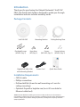
Package Contents
UniFi AP-PRO Mounting Bracket Ceiling Backing Plate
Flat Head Screws
(M3x50, Qty. 3)
Keps Nuts
(M3, Qty. 3)
Screws
(M2.9x20, Qty. 3)
Screw Anchors
(M3x20, Qty. 3)
802.11n PRO Access Point
Model: UAP-PRO
Gigabit PoE (48V, 0.5A)
with Mounting Bracket
Power Cord Quick Start Guide
Installation Requirements
• CAT5/6 cable
• Phillips screwdriver
• Drill and drill bit (6 mm for wall-mounting or 3 mm for
ceiling-mounting)
• Optional: Drywall or keyhole saw (to cut 25 mm hole for
Ethernet cable feed)
TERMS OF USE: All Ethernet cabling runs must use CAT5 (or above). It is the customer’s
responsibility to follow local country regulations, including operation within legal frequency
channels, output power, indoor cabling requirements, and Dynamic Frequency Selection
(DFS) requirements.

System Requirements
• Linux, MacOSX, or Microsoft Windows 7/8
• Java Runtime Environment 1.6 (or above)
• Web Browser: Mozilla Firefox, Google Chrome, or Microsoft
Internet Explorer 8 (or above)
• UniFi Controller software (available at:
downloads.ubnt.com/unifi)
Network Topology Requirements
• A DHCP-enabled network (for the AP to obtain an IP address
as well as for the wireless clients after deployment)
• A management station computer running the UniFi
Controller software, located either onsite and connected to
the same Layer-2 network, or off-site in a cloud or NOC
UAP-Pro
or
Network Health
www
WAN LAN
WLAN
VOIP
www
WAN LAN WLAN VOIP
IP
DNS
GATEWAY
ACTIVE CLIENTS
DOWN
UP
SWITCHES
USERS
GUESTS
DOWN
UP
APS
USERS
GUESTS
DOWN
UP
PHONES
EXTENSION
CALLS IN
CALLS OUT
XXX.XXX.XXX.XXX
XXX.XXX.XXX.XXX
192
0
0
0
0
0
0
162
2
0
0
0
30
4
3
6
0
DASHBOARD
MAP
DEVICES
CLIENTS
CALLS
STATISTICS
INSIGHTS
SETTINGS
CURRENT SITE
Default
REFRESH RATE
2 minutes
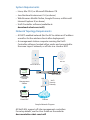
O-Site
Cloud/NOC
On-Site
Management
Station
UniFi Switch
UniFi
Security
Gateway
Internet
LAN
WAN
1G
UAP-AC Outdoor
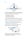
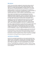
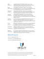
Sample Network Diagram
All UniFi APs support off-site management controllers.
For setup details, see the User Guide on the website:
documentation.ubnt.com/unifi

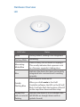
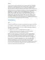
Hardware Overview
LED
LED Color Status
White
Factory default, waiting to be integrated.
Flashing White
Initializing.
Alternating
White/Blue
Device is busy; do not touch or unplug it.
This usually indicates that a process such
as a firmware upgrade is taking place.
Blue
Indicates the device has been successfully
integrated into a network and is working
properly.
Quickly
Flashing Blue
This is used to locate an AP.
When you click Locate in the UniFi
Controller software, the LED on the AP will
flash. It will also flash the location of the AP
on the map three times and then stop.
Steady Blue
with occasional
flashing
Indicates the device is in an isolated state
(all WLANs are brought down until an
uplink is found).

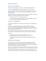
Ports
Main/48V
Ethernet Port
Secondary
Ethernet Port
Reset Button
Cable Feed Plug
Main/48V This Gigabit Ethernet port is used to connect the
power and should be connected to the LAN and DHCP server.
Power can be provided by any of the following:
• Included Gigabit PoE adapter
• 48V, 802.3af compliant switch
• Ubiquiti Networks UniFi Switch
• Ubiquiti Networks TOUGHSwitch
™
PRO, model TS-8-PRO
Secondary This Gigabit Ethernet port is used for bridging.
Reset This button serves two functions for the UniFi AP-PRO:
• Restart Press and release the Reset button quickly.
• Restore to Factory Default Settings Press and hold the
Reset button for more then five seconds.
Cable Feed Plug If your Ethernet cable feeds along the
mounting surface, remove theCable Feed Plug.
Locking
Clip
Mounting
Bracket
Locking Clip During installation, the Locking Clip on
the Mounting Bracket locks into the Locking Notch on the
UniFiAP-PRO to help prevent theft.

Hardware Installation
The UniFi AP-PRO can be mounted to the wall or ceiling.
Perform the steps for the appropriate installation:
Wall Mount
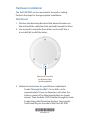
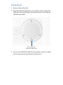
1. Position the Mounting Bracket at the desired location on
the wall with the cable feed slot pointed towards the floor.
2. Use a pencil to mark the three holes on the wall. Use a
6mm drill bit to drill the holes.
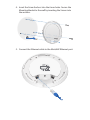
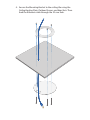
Optional 25 mm Hole
for Ethernet Cable
Feed through Wall
3. Follow the instruction for your Ethernet cable feed:
- Feeds Through the Wall Cut or drill a circle
approximately 25 mm in diameter, just below the
bottom center of the Mounting Bracket (as shown
above). Then feed the CAT5/6 cable through the hole.
- Feeds Along the Mounting Surface Remove the
Cable Feed Plug on the side of the UniFi AP-PRO.
*640-00207-01*
640-00207-01

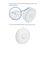
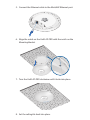
4. Insert the Screw Anchors into the 6 mm holes. Secure the
Mounting Bracket to the wall by inserting the Screws into
the anchors.
5. Connect the Ethernet cable to the Main/48V Ethernet port.

6. Align the notch on the UniFi AP-PRO with the notch on the
Mounting Bracket.
7. Turn the UniFi AP-PRO clockwise until it locks into place.

Ceiling Mount
1. Remove the ceiling tile.
2. Place the Mounting Bracket in the center of the ceiling tile.
Mark the three mounting screw holes and 25 mm hole for
the Ethernet cable.
25 mm Hole for
Ethernet Cable Feed
3. Use a 3 mm drill bit to drill the screw holes, and cut or drill
the 25 mm hole for the Ethernet cable feed.

4. Secure the Mounting Bracket to the ceiling tile using the
Ceiling Backing Plate, Flathead Screws, and KepsNuts. Then
feed the Ethernet cable through the 25mmhole.

5. Connect the Ethernet cable to the Main/48V Ethernet port.
6. Align the notch on the UniFi AP-PRO with the notch on the
Mounting Bracket.
7. Turn the UniFi AP-PRO clockwise until it locks into place.
8. Set the ceiling tile back into place.

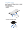
Powering the UniFi AP-PRO
The UniFi AP-PRO can be powered by the included Gigabit PoE
adapter or a compatible PoE device.
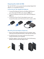
Connecting to the Gigabit PoE Adapter
1. Connect the Ethernet cable from the Main/48V Ethernet
port of the UniFi AP-PRO to the adapter’s POE port.
2. Connect an Ethernet cable from your LAN to the adapter’s
LAN port.
3. Connect the Power Cord to the adapter’s power port.
Connect the other end of the Power Cord to a power outlet.
Mounting the PoE Adapter (Optional)
1. Remove the PoE Mounting Bracket from the adapter, place
the bracket at the desired location, and mark the two holes.
2. Pre-drill the holes if necessary, and secure the bracket
using two fasteners (not included).
3. Align the adapter’s slots with the tabs of the PoE Mounting
Bracket, and then slide the adapterdown.

Connecting to a PoE Device
Connect the other end of the Ethernet cable coming from the
Main/48V Ethernet port on the UniFi AP directly to a PoE port
on one of the following:
• 48V, 802.3af compliant switch
• UniFi Switch
1 3 5 7 9 11 13 15 17 19 21 22
2 4 6 8 10 12 14 16 18 20 22 24
SPF1
SPF2
UniFi Switch Power Connection Diagram
• TOUGHSwitch PRO, model TS-8-PRO
TOUGHSwitch Power Connection Diagram

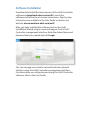
Software Installation
Download and install the latest version of the UniFi Controller
software at downloads.ubnt.com/unifi. Launch the
software and follow the on-screen instructions. Step-by-step
instructions are available in the User Guide located on our
website: documentation.ubnt.com/unifi
After you have installed the software and run the UniFi
Installation Wizard, a login screen will appear for the UniFi
Controller management interface. Enter the Admin Name and
Password that you created and click Login.
You can manage your wireless network and view network
statistics using the UniFi Controller management interface.
For information on configuring and using the UniFi Controller
software, refer to the User Guide.

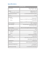
Specifications
UniFi AP PRO
Dimensions 200 x 200 x 36.5 mm
(7.87 x 7.87 x 1.44")
Weight
Mounting Kits Included
298 g (10.51 oz)
358 g (12.63 oz)
Networking Interfaces (2) 10/100/1000 Ethernet Ports
Buttons Reset
Antennas
2.4 GHz
5 GHz
3 Integrated
(Supports 3x3 MIMO with Spatial Diversity)
2 Integrated
(Supports 2x2 MIMO with Spatial Diversity)
Wi-Fi Standards 802.11 a/b/g/n
Power Method Passive Power over Ethernet (48V),
802.3af Supported
Power Supply 48V, 0.5A PoE Gigabit Adapter (Included)
Max. Power Consumption 12W
Max. TX Power
2.4 GHz
5 GHz
30 dBm
22 dBm
BSSID Up to Four per Radio
Power Save Supported
Wireless Security WEP, WPA-PSK, WPA-Enterprise
(WPA/WPA2, TKIP/AES)
Certications CE, FCC, IC
Mounting Wall/Ceiling (Kits Included)
Operating Temperature -10 to 70° C
(14 to 158° F)
Operating Humidity 5 to 80% Noncondensing

Safety Notices
1. Read, follow, and keep these instructions.
2. Heed all warnings.
3. Only use attachments/accessories specified by the manufacturer.
WARNING: Do not use this product in location that can
be submerged by water.
WARNING: Avoid using this product during an electrical
storm. There may be a remote risk of electric shock from
lightning.
Electrical Safety Information
1. Compliance is required with respect to voltage, frequency, and current
requirements indicated on the manufacturer’s label. Connection to a
different power source than those specified may result in improper
operation, damage to the equipment or pose a fire hazard if the
limitations are not followed.
2. There are no operator serviceable parts inside this equipment. Service
should be provided only by a qualified service technician.
3. This equipment is provided with a detachable power cord which has
an integral safety ground wire intended for connection to a grounded
safety outlet.
a. Do not substitute the power cord with one that is not the provided
approved type. Never use an adapter plug to connect to a 2-wire
outlet as this will defeat the continuity of the grounding wire.
b. The equipment requires the use of the ground wire as a part of the
safety certification, modification or misuse can provide a shock
hazard that can result in serious injury or death.
c. Contact a qualified electrician or the manufacturer if there
are questions about the installation prior to connecting the
equipment.
d. Protective earthing is provided by Listed AC adapter. Building
installation shall provide appropriate short-circuit backup
protection.
e. Protective bonding must be installed in accordance with local
national wiring rules and regulations.

Limited Warranty
UBIQUITI NETWORKS, Inc (“UBIQUITI NETWORKS”) warrants that the
product(s) furnished hereunder (the “Product(s)”) shall be free from defects
in material and workmanship for a period of one (1) year from the date
of shipment by UBIQUITI NETWORKS under normal use and operation.
UBIQUITI NETWORKS’ sole and exclusive obligation and liability under
the foregoing warranty shall be for UBIQUITI NETWORKS, at its discretion,
to repair or replace any Product that fails to conform to the above
warranty during the above warranty period. The expense of removal and
reinstallation of any Product is not included in this warranty. The warranty
period of any repaired or replaced Product shall not extend beyond its
original term.
Warranty Conditions
The above warranty does not apply if the Product:
(I) has been modified and/or altered, or an addition made thereto,
except by Ubiquiti Networks, or Ubiquiti Networks’ authorized
representatives, or as approved by Ubiquiti Networks in writing;
(II) has been painted, rebranded or physically modified in any way;
(III) has been damaged due to errors or defects in cabling;
(IV) has been subjected to misuse, abuse, negligence, abnormal
physical, electromagnetic or electrical stress, including lightning
strikes, or accident;
(V) has been damaged or impaired as a result of using third party
firmware;
(VI) has no original Ubiquiti MAC label, or is missing any other original
Ubiquiti label(s); or
(VII) has not been received by Ubiquiti within 30 days of issuance of
the RMA.
In addition, the above warranty shall apply only if: the product has been
properly installed and used at all times in accordance, and in all material
respects, with the applicable Product documentation; all Ethernet cabling
runs use CAT5 (or above), and for outdoor installations, shielded Ethernet
cabling is used, and for indoor installations, indoor cabling requirements
are followed.
Returns
No Products will be accepted for replacement or repair without obtaining
a Return Materials Authorization (RMA) number from UBIQUITI NETWORKS
during the warranty period, and the Products being received at UBIQUITI
NETWORKS’ facility freight prepaid in accordance with the RMA process of
UBIQUITI NETWORKS. Products returned without an RMA number will not
be processed and will be returned freight collect or subject to disposal.
Information on the RMA process and obtaining an RMA number can be
found at: www.ubnt.com/support/warranty.

Disclaimer
EXCEPT FOR ANY EXPRESS WARRANTIES PROVIDED HEREIN, UBIQUITI
NETWORKS, ITS AFFILIATES, AND ITS AND THEIR THIRD PARTY DATA,
SERVICE, SOFTWARE AND HARDWARE PROVIDERS HEREBY DISCLAIM
AND MAKE NO OTHER REPRESENTATION OR WARRANTY OF ANY KIND,
EXPRESS, IMPLIED OR STATUTORY, INCLUDING, BUT NOT LIMITED TO,
REPRESENTATIONS, GUARANTEES, OR WARRANTIES OF MERCHANTABILITY,
ACCURACY, QUALITY OF SERVICE OR RESULTS, AVAILABILITY,
SATISFACTORY QUALITY, LACK OF VIRUSES, QUIET ENJOYMENT, FITNESS
FOR A PARTICULAR PURPOSE AND NON-INFRINGEMENT AND ANY
WARRANTIES ARISING FROM ANY COURSE OF DEALING, USAGE OR
TRADE PRACTICE IN CONNECTION WITH SUCH PRODUCTS AND SERVICES.
BUYER ACKNOWLEDGES THAT NEITHER UBIQUITI NETWORKS NOR
ITS THIRD PARTY PROVIDERS CONTROL BUYER’S EQUIPMENT OR THE
TRANSFER OF DATA OVER COMMUNICATIONS FACILITIES, INCLUDING
THE INTERNET, AND THAT THE PRODUCTS AND SERVICES MAY BE
SUBJECT TO LIMITATIONS, INTERRUPTIONS, DELAYS, CANCELLATIONS
AND OTHER PROBLEMS INHERENT IN THE USE OF COMMUNICATIONS
FACILITIES. UBIQUITI NETWORKS, ITS AFFILIATES AND ITS AND THEIR THIRD
PARTY PROVIDERS ARE NOT RESPONSIBLE FOR ANY INTERRUPTIONS,
DELAYS, CANCELLATIONS, DELIVERY FAILURES, DATA LOSS, CONTENT
CORRUPTION, PACKET LOSS, OR OTHER DAMAGE RESULTING FROM ANY
OF THE FOREGOING. In addition, UBIQUITI NETWORKS does not warrant
that the operation of the Products will be error-free or that operation will
be uninterrupted. In no event shall UBIQUITI NETWORKS be responsible
for damages or claims of any nature or description relating to system
performance, including coverage, buyer’s selection of products (including
the Products) for buyer’s application and/or failure of products (including
the Products) to meet government or regulatory requirements.
Limitation of Liability
EXCEPT TO THE EXTENT PROHIBITED BY LOCAL LAW, IN NO EVENT WILL
UBIQUITI OR ITS SUBSIDIARIES, AFFILIATES OR SUPPLIERS BE LIABLE FOR
DIRECT, SPECIAL, INCIDENTAL, CONSEQUENTIAL OR OTHER DAMAGES
(INCLUDING LOST PROFIT, LOST DATA, OR DOWNTIME COSTS), ARISING
OUT OF THE USE, INABILITY TO USE, OR THE RESULTS OF USE OF THE
PRODUCT, WHETHER BASED IN WARRANTY, CONTRACT, TORT OR OTHER
LEGAL THEORY, AND WHETHER OR NOT ADVISED OF THE POSSIBILITY OF
SUCH DAMAGES.

Note
Some countries, states and provinces do not allow exclusions of implied
warranties or conditions, so the above exclusion may not apply to you.
You may have other rights that vary from country to country, state to
state, or province to province. Some countries, states and provinces do not
allow the exclusion or limitation of liability for incidental or consequential
damages, so the above limitation may not apply to you. EXCEPT TO
THE EXTENT ALLOWED BY LOCAL LAW, THESE WARRANTY TERMS DO
NOT EXCLUDE, RESTRICT OR MODIFY, AND ARE IN ADDITION TO, THE
MANDATORY STATUTORY RIGHTS APPLICABLE TO THE LICENSE OF ANY
SOFTWARE (EMBEDDED IN THE PRODUCT) TO YOU. The United Nations
Convention on Contracts for the International Sale of Goods shall not apply
to any transactions regarding the sale of the Products.
Compliance
FCC
Changes or modifications not expressly approved by the party responsible
for compliance could void the user’s authority to operate the equipment.
This device complies with Part 15 of the FCC Rules. Operation is subject to
the following two conditions:
1. This device may not cause harmful interference, and
2. This device must accept any interference received, including
interference that may cause undesired operation.
NOTE: This equipment has been tested and found to comply with the
limits for a Class A digital device, pursuant to part 15 of the FCC Rules.
These limits are designed to provide reasonable protection against
harmful interference when the equipment is operated in a commercial
environment. This equipment generates, uses, and can radiate radio
frequency energy and, if not installed and used in accordance with
the instruction manual, may cause harmful interference to radio
communications. Operations of this equipment in a residential area is likely
to cause harmful interference in which case the user will be required to
correct the interference at his own expense.

Industry Canada
CAN ICES-3(A)/NMB-3(A)
This Class A digital apparatus complies with Canadian CAN ICES-3(A).
To reduce potential radio interference to other users, the antenna
type and its gain should be so chosen that the equivalent isotropically
radiated power (e.i.r.p.) is not more than that permitted for successful
communication.
This device complies with Industry Canada licence-exempt RSS standard(s).
Operation is subject to the following two conditions:
1. This device may not cause interference, and
2. This device must accept any interference, including interference that
may cause undesired operation of the device.
CAN ICES-3(A)/NMB-3(A)
Cet appareil numérique de la classe A est conforme à la norme NMB-3(A)
Canada.
Pour réduire le risque d’interférence aux autres utilisateurs, le type
d’antenne et son gain doivent être choisies de façon que la puissance
isotrope rayonnée équivalente (PIRE) ne dépasse pas ce qui est nécessaire
pour une communication réussie.
Cet appareil est conforme à la norme RSS Industrie Canada exempts de
licence norme(s). Son fonctionnement est soumis aux deux conditions
suivantes:
1. Cet appareil ne peut pas provoquer d’interférences et
2. Cet appareil doit accepter toute interférence, y compris les
interférences qui peuvent causer un mauvais fonctionnement du
dispositif.
RF Exposure Warning
The antennas used for this transmitter must be installed to provide a
separation distance of at least 20 cm from all persons and must not be
located or operating in conjunction with any other antenna or transmitter,
except as listed for this product’s certification.
Les antennes utilisées pour cet émetteur doit être installé pour fournir une
distance de séparation d’au moins 20 cm de toutes les personnes et ne doit
pas être situé ou opérant en conjonction avec une autre antenne ou un
autre émetteur, sauf dans les cas énumérés à la certification de ce produit.
Pagina se încarcă...
Pagina se încarcă...
Pagina se încarcă...
Pagina se încarcă...
-
 1
1
-
 2
2
-
 3
3
-
 4
4
-
 5
5
-
 6
6
-
 7
7
-
 8
8
-
 9
9
-
 10
10
-
 11
11
-
 12
12
-
 13
13
-
 14
14
-
 15
15
-
 16
16
-
 17
17
-
 18
18
-
 19
19
-
 20
20
-
 21
21
-
 22
22
-
 23
23
-
 24
24


în alte limbi
- English: Ubiquiti UAP-PRO Quick start guide
- italiano: Ubiquiti UAP-PRO Guida Rapida
Lucrări înrudite
-
Ubiquiti Networks UniFi Manualul utilizatorului
-
Ubiquiti UniFi USG Ghid de inițiere rapidă
-
Ubiquiti UAP-LR Ghid de inițiere rapidă
-
-
Ubiquiti Networks Réseau de points de UAP-AC-LITE-5 accès Manual de utilizare
-
-
-
-
-
Ubiquiti Networks UAP-AC Manualul utilizatorului