
DOC024.98.93052
POLYMETRON Model
8350/8351 Probes
06/2018, Edition 7
User Manual
Benutzerhandbuch
Manuale utente
Manuel d'utilisation
Manual de usuario
Manual do utilizador
Návod k použití
Brugervejledning
Gebruikershandleiding
Instrukcja obsługi
Bruksanvisning
Käyttäjän käsikirja
Kullanım Kılavuzu
Korisnički priručnik
Manual de utilizare
Navodila za uporabo
Εγχειρίδιο χρήστη

English..............................................................................................................................3
Deutsch............................................................................................................................ 9
Italiano............................................................................................................................ 15
Français......................................................................................................................... 21
Español.......................................................................................................................... 27
Português...................................................................................................................... 33
Čeština........................................................................................................................... 39
Dansk..............................................................................................................................45
Nederlands....................................................................................................................51
Polski.............................................................................................................................. 57
Svenska......................................................................................................................... 63
Suomi..............................................................................................................................69
Türkçe.............................................................................................................................75
Hrvatski.......................................................................................................................... 81
Română......................................................................................................................... 87
Slovenski....................................................................................................................... 93
Ελληνικά........................................................................................................................ 99
2

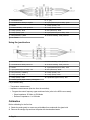
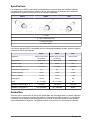
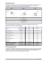
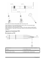
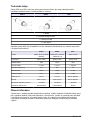
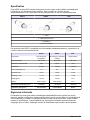
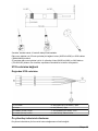
Specifications
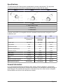
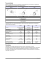
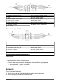
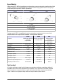
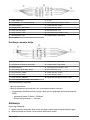
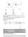
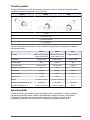
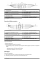
The 8350 pH and 8351 Redox probes are dedicated for process measurements. The pH probes
incorporate impedance control and a temperature sensor in contact with the sample.
8350.4 8350.5 8351
1 - Glass
2 - Tube containing PT100
3 - Platinum ring
4 - PTFE Junction
A special model (8350.3) is compatible with all the standard accessories and is designed for use in
hydrofluoric acid.
8350.4 8350.5 8351
Application Measuring pH at high
temperatures
Measuring pH in a
waste water
environment
Measuring redox
Junction type Flat, PTFE Flat, PTFE Flat, PTFE
Body material PPS CPVC PPS
Measurement range 0-14 pH 0-12 pH ± 1500 mV
Maximum temperature (°C) 110 80 110
Maximum pressure 10 bar 10 bar 10 bar
Drift (/ week) < 3 mV < 3 mV < 3 mV
Offset @ pH7 ± 20 mV ± 20 mV N/A
Slope 56-61 mV/pH 56-61 mV/pH N/A
Reference impedance @ 25°C < 50 Kohm < 50 Kohm < 50 Kohm
Glass impedance @ 25°C 150-500 Mohm 150-500 Mohm Platinum
General information
In no event will the manufacturer be liable for direct, indirect, special, incidental or consequential
damages resulting from any defect or omission in this manual. The manufacturer reserves the right to
make changes in this manual and the products it describes at any time, without notice or obligation.
Revised editions are found on the manufacturer’s website.
English
3

Safety information
N O T I C E
The manufacturer is not responsible for any damages due to misapplication or misuse of this product including,
without limitation, direct, incidental and consequential damages, and disclaims such damages to the full extent
permitted under applicable law. The user is solely responsible to identify critical application risks and install
appropriate mechanisms to protect processes during a possible equipment malfunction.
Please read this entire manual before unpacking, setting up or operating this equipment. Pay
attention to all danger and caution statements. Failure to do so could result in serious injury to the
operator or damage to the equipment.
Make sure that the protection provided by this equipment is not impaired. Do not use or install this
equipment in any manner other than that specified in this manual.
Use of hazard information
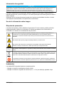
Precautionary labels
Read all labels and tags attached to the instrument. Personal injury or damage to the instrument
could occur if not observed. A symbol on the instrument is referenced in the manual with a
precautionary statement.
This is the safety alert symbol. Obey all safety messages that follow this symbol to avoid potential
injury. If on the instrument, refer to the instruction manual for operation or safety information.
This symbol indicates that a risk of electrical shock and/or electrocution exists.
This symbol indicates the presence of devices sensitive to Electro-static Discharge (ESD) and
indicates that care must be taken to prevent damage with the equipment.
This symbol, when noted on a product, indicates the instrument is connected to alternate current.
Electrical equipment marked with this symbol may not be disposed of in European domestic or
public disposal systems. Return old or end-of-life equipment to the manufacturer for disposal at no
charge to the user.
Products marked with this symbol indicates that the product contains toxic or hazardous substances
or elements. The number inside the symbol indicates the environmental protection use period in
years.
Installation
The probes can be installed in any position.
• Insertion mounting: screw-in or flange fitting
• Immersion mounting: immersion shafts (0.5, 1, or 1.5 meters) with fixed, adjustable or clip-type
flange.
4
English

The probes are fitted with 10 metres of cable as standard.
For longer cable lengths (up to 25 meters) use a junction box (08350=A=8500) and the 2654 cable
(358048,00000).
For cable lengths greater than 25 meters, use a pre-amplifier unit (08350=A=8000) and the
2666 cable (370=506=025). In this case it will not be possible to monitor the impedance.
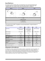
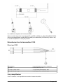
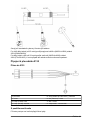
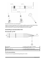
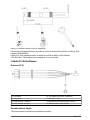
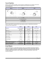
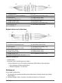
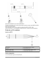
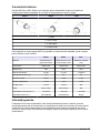
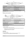
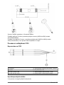
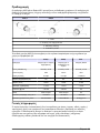
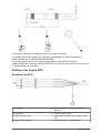
Connection to the 9135 transmitter
Directly to the 9135
1 pH module 5 Input (measured pH or redox) - transparent
2 Probe 6 Ref. (reference) - black
3 Temp+ (PT100) - white 7 Liquid earth (liquid contact) - blue
4 Temp- (PT100) - red 8 External shielding - EMC protection
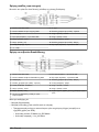
Using the pre-amplifier unit
With this scenario it is impossible to connect the solution ground.
English
5

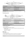
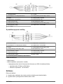
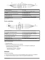
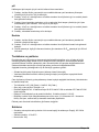
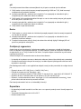
1 Model 2666 cable 9 -V - grey
2 Model 08350=A=8000 pre-amplifier 10 Input (measured pH or ORP) - green
3 Sensor 11 Temp+ (Pt100) - red
4 External shielding - EMC protection 12 Temp- (Pt100) - white
5 Temp+ (Pt100) - white 13 Ref. (reference) - black
6 Temp- (Pt100) - pink 14 Input (measured pH or ORP) - clear
7 Ref. (reference) - yellow 15 External shielding - EMC protection
8 +V - brown
Using the junction box
1 Model 2654 cable 9 External shielding - EMC protection
2 Model 08350=A=8500 junction box 10 External shielding - EMC protection
3 Sensor 11 Input (measured pH or ORP) - clear
4 Input (measured pH or ORP) - core 12 Ref. (reference) - black
5 Ref. (reference) - shielding 13 Temp+ (Pt100) - red
6 Temp+ (Pt100) - white 14 Temp- (Pt100) - white
7 Temp- (Pt100) - violet 15 Liquid earth (liquid contact) - blue
8 Solution ground (liquid contact) - yellow/green
For pH sensors only:
• Temperature measurement
• Impedance measurement (blue wire from the controller):
• Program the control frequency upper and lower limits (refer to the 9500 user manual):
• Glass impedance: 50 Mohm to 500 Mohm
• Reference impedance: 1 to 100 kohm
Calibration
Before calibrating for the first time:
1. Shake the probe gently to remove any air bubbles from underneath the glass bulb.
2. Remove the storage cap and rinse the probe with demineralized water.
6
English

pH
Refer to the pH transmitter user manual to select the type of calibration.
1. Rinse the probe with the freshly prepared first buffer solution (pH 6.88 or 7.00) ideally at the same
temperature of the measurement sample.
2. Immerse the probe to a depth of 4 to 5 cm and wait for stable measurements (pH and
temperature) before calibrating.
3. Rinse the probe, first with demineralised water and then with the second buffer solution (pH close
to that of the process, 4.00 or 9.22).
4. Immerse the probe to a depth of 4 to 5cm and wait for stable measurements (pH and
temperature) before calibrating.
5. Rinse the probe in demineralized water.
Redox
1. Rinse the probe with a freshly prepared standard quinhydrone solution ideally at the same
temperature of the measurement sample.
2. Immerse the probe to a depth of 4 to 5 cm and wait for stable measurements before calibrating.
3. The measured potential is defined with respect to the Ag/AgCl reference system. Add 200 mV for
an E
H2
reference potential.
Cleaning and regeneration
These electrodes are considered as consumable items and therefore have a limited lifespan, largely
dependant on the application. Under normal conditions a typical lifespan would be about one year.
Before replacing them, however, simply cleaning the electrodes may regenerate them.
Such cleaning will be necessary whenever the following are observed:
• An offset from zero or a measurement drift (the reference system is contaminated)
• A significant drop in response time and a loss of slope (glass diaphragm or platinum ring dirty)
Provided the glass diaphragm is neither scratched nor cracked, follow one of the cleaning
procedures below:
• Salt deposits: HCl 0.1M (5 mins) + NaOH 0.1M (5 mins)
• Grease or oil film: Detergent + water
• Reference junction dirty: KCl 3M @ 60-80°C for 10 mins, then cool in KCl 3M @ 25°C
• Calcium, metal hydroxide or protein deposits: HCl 10% for 10 mins
• Deposits, wear on redox measurements: Aqua regia (1/1 concentrated HCl / concentrated HNO
3
).
This process must only be carried out by qualified individuals.
If the electrode response is still not improved, replace it.
Storage
• Never store the probes in air or with a dry protection cap. Moisten the cap with KCl 3M
• Storage temperature: 10 to 30°C
• Typical duration: 6 months
English
7

Probe and accessory part numbers
Description Item no.
Combination pH probe for hydrofluoric acid environments with integrated temperature
sensor.
08350=C=0003
Combination pH probe for high temperatures with protected sensor, impedance
control and integrated temperature sensor.
08350=C=0004
Combination pH probe for waste water environments incorporating a protected, flat
sensor, impedance control and integrated temperature sensor
08350=C=0005
Combination redox probe for high temperatures 08351=C=0000
PVC DN 40 flow chamber, flange fitting 08350=A=9500
PP immersion shaft, clip fitting (0.5, 1, 1.5 meter) 08350=A=1105/10/15
PP immersion shaft, adjustable flange (0.5, 1, 1.5 meter) 08350=A=1005/10/15
PP immersion shaft, fixed flange (0.5, 1, 1.5 meter) 08350=A=6005/10/15
PP chemical cleaning kit (nozzle and feed pipes) 08350=A=7000
Liquid reservoir unit 08350=A=4000
Junction box 08350=A=8500
Pre-amplifier for 8350 probes 08350=A=8000
Low-impedance cable, type 2666 370=506=025
High-impedance co-axial cable, type 2654 358048,00000
8 English

Spezifikationen
Die Sonden Ph 8350 und Redox 8351 sind für Messungen unter schwierigen Bedingungen
vorgesehen (Schmutz) und gegen Stösse geschützt. Die pH Sonden verfügen über einen
Temperaturfühler, der mit dem Prozess und der Impedanzkontrolle in Kontakt ist.
8350.4 8350.5 8351
1 - Glas
2 - Rohr mit PT100
3 - Platinenring
4 - Verbindung PTFE
Eine spezielle Version 8350.3, kompatible mit dem Standardzubehör, ermöglicht Kontakt mit
Fluorwasserstoffsäure.
8350.4 8350.5 8351
Anwendung pH-Messung bei hohen
Temperaturen
pH-Messung in
verschmutzender
Umgebung
Redox-Messung
Verbindungstyp Flach, PTFE Flach, PTFE Flach, PTFE
Körpermaterial PPS CPVC PPS
Arbeitsbereich 0-14 pH 0-12 pH ± 1500 mV
Max. Temperatur (°C) 110 80 110
Max. Druck 10 bar 10 bar 10 bar
Abweichung (/ Woche) < 3 mV < 3 mV < 3 mV
Offset @ pH7 ± 20 mV ± 20 mV N/A
Steilheit 56-61 mV/pH 56-61 mV/pH N/A
Referenz-Impendanz @ 25 °C < 50 Kohm < 50 Kohm < 50 Kohm
Glas-Impendanz @ 25 °C 150-500 Mohm 150-500 Mohm Platin
Allgemeine Informationen
Der Hersteller ist nicht verantwortlich für direkte, indirekte, versehentliche oder Folgeschäden, die
aus Fehlern oder Unterlassungen in diesem Handbuch entstanden. Der Hersteller behält sich
jederzeit und ohne vorherige Ankündigung oder Verpflichtung das Recht auf Verbesserungen an
diesem Handbuch und den hierin beschriebenen Produkten vor. Überarbeitete Ausgaben der
Bedienungsanleitung sind auf der Hersteller-Webseite erhältlich.
Deutsch
9

Sicherheitshinweise
H I N W E I S
Der Hersteller ist nicht für Schäden verantwortlich, die durch Fehlanwendung oder Missbrauch dieses Produkts
entstehen, einschließlich, aber ohne Beschränkung auf direkte, zufällige oder Folgeschäden, und lehnt jegliche
Haftung im gesetzlich zulässigen Umfang ab. Der Benutzer ist selbst dafür verantwortlich, schwerwiegende
Anwendungsrisiken zu erkennen und erforderliche Maßnahmen durchzuführen, um die Prozesse im Fall von
möglichen Gerätefehlern zu schützen.
Bitte lesen Sie dieses Handbuch komplett durch, bevor Sie dieses Gerät auspacken, aufstellen oder
bedienen. Beachten Sie alle Gefahren- und Warnhinweise. Nichtbeachtung kann zu schweren
Verletzungen des Bedieners oder Schäden am Gerät führen.
Stellen Sie sicher, dass die durch dieses Messgerät bereitgestellte Sicherheit nicht beeinträchtigt
wird. Verwenden bzw. installieren Sie das Messsystem nur wie in diesem Handbuch beschrieben.
Bedeutung von Gefahrenhinweisen
Warnaufkleber
Lesen Sie alle am Gerät angebrachten Aufkleber und Hinweise. Nichtbeachtung kann Verletzungen
oder Beschädigungen des Geräts zur Folge haben. Im Handbuch werden auf die am Gerät
angebrachten Symbole in Form von Warnhinweisen verwiesen.
Dies ist das Sicherheits-Warnsymbol. Befolgen Sie alle Sicherheitshinweise im Zusammenhang mit
diesem Symbol, um Verletzungen zu vermeiden. Wenn es am Gerät angebracht ist, beachten Sie
die Betriebs- oder Sicherheitsinformationen im Handbuch.
Dieses Symbol weist auf die Gefahr eines elektrischen Schlages hin, der tödlich sein kann.
Dieses Symbol zeigt das Vorhandensein von Geräten an, die empfindlich auf elektrostatische
Entladung reagieren. Es müssen Vorsichtsmaßnahmen getroffen werden, um die Geräte nicht zu
beschädigen.
Dieses Symbol weist darauf hin, dass das Instrument an Wechselstrom angeschlossen werden
muss.
Elektrogeräte, die mit diesem Symbol gekennzeichnet sind, dürfen nicht im normalen öffentlichen
Abfallsystem entsorgt werden. Senden Sie Altgeräte an den Hersteller zurück. Dieser entsorgt die
Geräte ohne Kosten für den Benutzer.
Produkte, die mit diesem Symbol gekennzeichnet sind, enthalten toxische oder gefährliche
Substanzen oder Elemente. Die Ziffer in diesem Symbol gibt den Umweltschutzzeitraum in Jahren
an.
Installation
Die Sonden 8350 können in allen Positionen installiert werden.
• Montage durch Einfügen : direktes Anschrauben oder Flansch
• Eintauch-Montage : Eintauch-Länge (0.5, 1, oder 1.5 m) mit festem oder anpassbarem Flansch
oder Clip.
10
Deutsch

Die Sonden haben ein 10 m langes Kabel.
Einen einfachen Anschlusskasten für bis zu 25 m verwenden (08350=A=8500) und das Kabel
2654 (358048,00000).
Bei grösserer Distanz einen Verstärker verwenden (08350=A=8000) und das Kabel
2666 (370=506=025). In diesem Fall ist die Impendanz-Kontrolle nicht mehr möglich.
Anschluss an den Übertrager 9135
Direkt an 9135
1 pH-Modul 5 Input (pH-Messung oder Redox) - transparent
2 Sonde 6 Ref. (Referenz) - schwarz
3 Temp+ (PT100) - weiss 7 Liq. earth (Flüssigkontakt) - blau
4 Temp- (PT100) - rot 8 Äusserer Schim - CEM Schutz
Verwendung des Vorverstärkers
Bei diesem Szenario ist es unmöglich, den Solution Ground zu verbinden.
Deutsch
11

1 Modell 2666 Kabel 9 -V - Grau
2 Modell 08350=A=8000 Vorverstärker 10 Eingang (pH oder ORP gemessen ) - Grün
3 Sensor 11 Temp+ (Pt100) - Rot
4 Äusserer Schim - EMV-Schutz 12 Temp- (Pt100) - Weiß
5 Temp+ (Pt100) - Weiß 13 Ref. (Referenz) - Schwarz
6 Temp- (Pt100) - Pink 14 Eingang (pH oder ORP gemessen ) - hell
7 Ref. (Referenz) - Gelb 15 Äusserer Schim - EMV-Schutz
8 +V - Braun
Verwendung des Anschlusskastens
1 Modell 2654 Kabel 9 Äusserer Schim - EMV-Schutz
2 Modell 08350=A=8500 Anschlusskasten 10 Äusserer Schim - EMV-Schutz
3 Sensor 11 Eingang (pH oder ORP gemessen ) - hell
4 Eingang (pH oder ORP gemessen ) - Seele 12 Ref. (Referenz) - Schwarz
5 Ref. (Referenz) - Abschirmung 13 Temp+ (Pt100) - Rot
6 Temp+ (Pt100) - Weiß 14 Temp- (Pt100) - Weiß
7 Temp- (Pt100) - Violett 15 Liquid earth (Flüssigkeitskontakt) - Blau
8 Solution Ground (Flüssigkeitskontakt) - Gelb/Grün
Nur für pH-Sensoren:
• Temperaturmessung
• Impendanzmessung (blaues Kabel vom Controller):
• Programmieren Sie die oberen und unteren Grenzen der Ansteuerfrequenz (siehe
9500 Bedienhandbuch):
• Glasimpedanz: 50 Mohm bis 500 Mohm
• Referenzimpedanz: 1 - 100 kohm
Kalibrierung
Vor dem ersten Kalibrierung :
1. Die Sonde leicht schütteln, damit alle Luftbalsen unter der Glashaube entfernt werden.
2. Die Lagerhaube abnehmen und die Sonde mit entmineralisiertem Wasser spülen.
12
Deutsch

pH
Siehe Anwenderhandbuch des Ph-Übertragers für die Wahl der Kalibrierung.
1. Die Sonde mit der ersten Pufferlösung spülen (6.88 oder 7.00 pH), frisch zubereitet und wenn
möglich bei derselben Temperatur wie die zu messende Flüssigkeit.
2. Eintauchen (etwa 4 bis 5 cm) und warten bis die Messung sich stabilisiert (pH und Temperatur)
bevor geeicht wird.
3. Die Sonde mit entmineralisiertem Wasser spülen, anschliessend in die zweite Pufferlösung
eintauchen (pH so nahe wie möglich am Prozess, 4.00 oder 9.22).
4. Eintauchen (etwa 4 bis 5 cm) und warten bis die Messung sich stabilisiert (pH und Temperatur)
bevor geeicht wird.
5. Die Sonde mit entmineralisiertem Wasser spülen.
Redox
1. Die Sonde mit einer Standard-Chinhydronlösung, frisch zubereitet und wenn möglich bei
derselben Temperatur wie die zu messende Flüssigkeit, spülen.
2. Eintauchen (etwa 4 bis 5 cm) und warten bis die Messung sich stabilisiert, bevor geeicht wird.
3. Das Messpotential wird im Verhältnis zum Referenzsystem Ag/AgCl definiert. 200 mV für die
Referenz des Potentials E
H2
hinzufügen.
Reinigung und Regenerierung
Die Elektroden werden als Verschleissteile angesehen und haben eine beschränkte Lebensdauer, je
nach Ar der Anwendung. Normalerweise beträgt ihre durchschnittliche Lebensdauer 1 Jahr. Vor dem
Austauschen können durch eine Reinigen der Elektroden korrekte Parameter wieder erzielt werden.
Diese Reinigung ist notwendig, wenn festgestellt wird :
• Eine Abweichung von Null oder eine Mess-Abweichung (Referenz-System kontaminiert)
• Eine bedeutende Verlängerung der Antwortzeit und ein Steigungs-Verlust (Glasmembrane oder
Platine verschmutzt.
Wenn die Glasmembrane weder verkratzt noch gebrochen ist, folgende Reinigungsprozeduren
durchführen :
• Salzablagerung : HCl 0.1 M (5 Min) + NaOH 0.1M (5 Min)
• Fett- oder Ölschicht : Reinigungsmittel + Wasser
• Referenz-Verbindung verschmutzt: KCl 3M @ 60-80 °C während 10 Min anschliessend Kühlung in
KCl 3M@25 °C
• Kalk-, Metallhydroxid-, Proteinablagerung : HCl 10% während 10 Min
• Ablagerung, Abnutzung auf Redox-Messung : Aqua Regia (HCl Konzentrat/HNO
3
Konzentrat 1/1)
Nur durch qualifiziertes Personal.
Wenn die Antwortzeit der Elektrode nicht verbessert wird, muss sie ausgetauscht werden.
Lagerung
• Die Sonden nicht an der Luft oder in einem trockenen Deckel lagern. Der Deckel muss mit KCl 3M
befeuchtet werden.
• Lagertemperatur : 10 und 30 °C
• Dauer : 6 Monate.
Deutsch
13

Sonden und Zubehörnummern
Beschreibung Teilenr.
Kombinierte Ph-Sonde für Flüssigkeit mit Fluorhydridsäure, integrierte
Temperaturmessung
08350=C=0003
Kombinierte Ph-Sonde für hohe Temperaturen, geschützter Fühler,
Impendanzkontrolle, integrierte Temperaturmessung
08350=C=0004
Kombinierte Ph-Sonde für verschmutzende Umgebung, geschützter Fühler,
Impendanzkontrolle, integrierte Temperaturmessung
08350=C=0005
Kombinierte Redox-Sonde für hohe Temperaturen 08351=C=0000
Kreislaufkammer DN 40 PVC, Befestigung Sonde mit Flansch 08350=A=9500
Eintauchrohr PP mit Clip (0.5, 1, 1.5m) 08350=A=1105/10/15
Eintauchrohr PP mit Gleitflansch (0.5, 1, 1.5m) 08350=A=1005/10/15
Eintauchrohr PP mit festem Flansch (0.5, 1, 1.5m) 08350=A=6005/10/15
Chemisches Reinigungsset PP (Ventil + Versorgungsschlauch) 08350=A=7000
Rückhaltevorrichtung für Flüssigkeit 08350=A=4000
Verteilerdose 08350=A=8500
Verstärker für Sonde 8350 08350=A=8000
Kabel 2666 niedrige Impendanz 370=506=025
Coaxial-Kabel 2654 für Hochimpendanz-Anschluss 358048,00000
14 Deutsch

Specifiche
Le sonde di pH 8350 e redox 8351 sono destinate alle misure in condizioni difficili (incrostazione) e
sono protette contro gli urti…). Le sonde di pH dispongono di un sensore di temperatura in contatto
con il processo e di controllo di impedenza.
8350.4 8350.5 8351
1 - Vetro
2 - Tubo contenente la PT100
3 - Anello di platino
4 - Connessione PTFE
Una versione speciale 8350.3, compatibile con gli esistenti accessori standard, consente la messa in
contatto con l’acido fluoridrico.
8350.4 8350.5 8351
Applicazione Misura di pH alta
temperatura
Misura di pH in
ambiente sporco
Misura redox
Tipo connessione Piana, PTFE Piana, PTFE Piana, PTFE
Materiali corpo PPS CPVC PPS
Intervallo di misurazione 0-14 pH 0-12 pH ± 1500 mV
Temperatura massima (°C) 110 80 110
Pressione massima 10 bar 10 bar 10 bar
Deriva (/ settimana) < 3 mV < 3 mV < 3 mV
Offset @ pH7 ± 20 mV ± 20 mV N/D
Pendenza 56-61 mV/pH 56-61 mV/pH N/D
Impedenza riferimento @ 25 °C < 50 Kohm < 50 Kohm < 50 Kohm
Impedenza vetro @ 25 °C 150-500 Mohm 150-500 Mohm Platino
Informazioni generali
In nessun caso, il produttore potrà essere ritenuto responsabile per danni diretti, indiretti o accidentali
per qualsiasi difetto o omissione relativa al presente manuale. Il produttore si riserva il diritto di
apportare eventuali modifiche al presente manuale e ai prodotti ivi descritti in qualsiasi momento
senza alcuna notifica o obbligo preventivi. Le edizioni riviste sono presenti nel sito Web del
produttore.
Italiano
15

Informazioni sulla sicurezza
A V V I S O
Il produttore non sarà da ritenersi responsabile in caso di danni causati dall'applicazione errata o dall'uso errato di
questo prodotto inclusi, a puro titolo esemplificativo e non limitativo, i danni incidentali e consequenziali; inoltre
declina qualsiasi responsabilità per tali danni entro i limiti previsti dalle leggi vigenti. La responsabilità relativa
all'identificazione dei rischi critici dell'applicazione e all'installazione di meccanismi appropriati per proteggere le
attività in caso di eventuale malfunzionamento dell'apparecchiatura compete unicamente all'utilizzatore.
Prima di disimballare, installare o utilizzare l’apparecchio, si prega di leggere l’intero manuale. Si
raccomanda di leggere con attenzione e rispettare le istruzioni riguardanti note di pericolosità. La non
osservanza di tali indicazioni potrebbe comportare lesioni gravi all'operatore o danni all'apparecchio.
Assicurarsi che i dispositivi di sicurezza insiti nell'apparecchio siano efficaci all'atto della messa in
servizio e durante l'utilizzo dello stesso. Non utilizzare o installare questa apparecchiatura in modo
diverso da quanto specificato nel presente manuale.
Utilizzo dei segnali di avvertimento
Etichette precauzionali
Leggere sempre tutte le indicazioni e le targhette di segnalazione applicate all'apparecchio. La
mancata osservanza delle stesse può infatti causare lesioni personali o danni allo strumento. Un
simbolo sullo strumento è indicato nel manuale unitamente a una frase di avvertenza.
Questo è il simbolo di allarme sicurezza. Seguire tutti i messaggi di sicurezza dopo questo simbolo
per evitare potenziali lesioni. Se sullo strumento, fare riferimento al manuale delle istruzioni per il
funzionamento e/o informazioni sulla sicurezza.
Questo simbolo indica un rischio di scosse elettriche e/o elettrocuzione.
Questo simbolo indica la presenza di dispositivi sensibili alle scariche elettrostatiche (ESD, Electro-
static Discharge) ed è pertanto necessario prestare la massima attenzione per non danneggiare
l'apparecchiatura.
Questo simbolo, quando applicato su un prodotto, indica che lo strumento è collegato a corrente
alternata.
Le apparecchiature elettriche contrassegnate con questo simbolo non possono essere smaltite
attraverso sistemi domestici o pubblici europei. Restituire le vecchie apparecchiature al produttore il
quale si occuperà gratuitamente del loro smaltimento.
I prodotti contrassegnati dal presente simbolo contengono sostanze o elementi tossici o pericolosi.
Il numero all'interno del simbolo indica il periodo di utilizzo senza rischio per l'ambiente, espresso in
anni.
Installazione
Le sonde 8350 possono essere installate in tutte le posizioni.
• Montaggio con inserimento : avvitatura diretta o flangia
• Montaggio con immersione : Lunghezze d’inserimento (0.5; 1; 1.5 m) con flangia fissa,
aggiustabile o clips.
16
Italiano

Le sonde sono dotate di 10 metri di cavo.
Utilizzare una scatola di connessione semplice fino a 25 m (08350=A=8500) e il cavo
2654 (358048,00000).
Utilizzare un preamplificatore per una lunghezza superiore (08350=A=8000) e il cavo
2666 (370=506=025). In tal caso, non sarà più possibile il controllo di impedenza.
Collegamento sul trasmettitore 9135
Diretto su 9135
1 pH modulo 5 Input (misura pH o redox) - trasparente
2 Sonda 6 Ref. (riferimento) - nero
3 Temp+ (PT100) - blanco 7 Liquid earth (contatto liquido) - blu
4 Temp- (PT100) - rosso 8 Schermatura esterna - Protezione CEM
Su preamplificatore
In questo caso non è possibile collegare la messa a terra della soluzione.
Italiano
17

1 Cavo modello 2666 9 -V - grigio
2 Preamplificatore modello 08350=A=8000 10 Ingresso (pH o ORP misurato) - verde
3 Sensore 11 Temp+ (Pt100) - rosso
4 Schermatura esterna - Protezione CEM 12 Temp- (Pt100) - bianco
5 Temp+ (Pt100) - bianco 13 Ref. (riferimento) - nero
6 Temp- (Pt100) - rosa 14 Ingresso (pH o ORP misurato) - libero
7 Ref. (riferimento) - giallo 15 Schermatura esterna - Protezione CEM
8 +V - marrone
Su scatola di connessione
1 Cavo modello 2654 9 Schermatura esterna - Protezione CEM
2 Scatola di connessione modello 08350=A=8500 10 Schermatura esterna - Protezione CEM
3 Sensore 11 Ingresso (pH o ORP misurato) - libero
4 Ingresso (pH o ORP misurato) - nucleo 12 Ref. (riferimento) - nero
5 Ref. (riferimento) - schermatura 13 Temp+ (Pt100) - rosso
6 Temp+ (Pt100) - bianco 14 Temp- (Pt100) - bianco
7 Temp- (Pt100) - viola 15 Messa a terra del liquido (contatto liquido) - blu
8 Messa a terra della soluzione (contatto liquido) -
giallo/verde
Solo per sensori pH:
• Misura della temperatura
• Misura dell'impedenza (cavo blu dal controller):
• Programmare i limiti superiore e inferiore della frequenza di controllo (consultare il manuale per
l'utente del modello 9500):
• Impedenza vetro : 50 Mohm - 500 Mohm
• Impedenza di riferimento : 1 - 100 kohm
Calibrazione
Prima di effettuare la prima calibratura :
18
Italiano

1. Scuotere lievemente la sonda per eliminare tutte le bolle d’aria sotto il bulbo di vetro.
2. Rimuovere il cappuccio di stoccaggio e sciacquare la sonda con acqua demineralizzata.
pH
Riferirsi al manuale operativo del trasmettitore pH per la scelta del tipo di calibratura.
1. Sciacquare la sonda con la prima soluzione tampone (6.88 o 7.00 pH) appena preparata e
preferibilmente alla stessa temperatura dell'ambiente da misurare.
2. Immergerla (su 4 o 5 cm) e aspettare la stabilizzazione della misura (pH e temperatura) prima di
calibrarla.
3. Sciacquare la sonda con acqua demineralizzata, quindi con la seconda soluzione tampone (pH
più vicino al processo, 4.00 o 9.22).
4. Immergerla (su 4 o 5 cm) e aspettare la stabilizzazione della misura (pH e temperatura) prima di
calibrarla.
5. Sciacquare la sonda con acqua demineralizzata.
Redox
1. Sciacquare la sonda con una soluzione standard di quinidronio preparata di recente e
preferibilmente alla stessa temperatura dell'ambiente da misurare.
2. Immergerla (su 4 o 5 cm) e aspettare la stabilizzazione della misura prima di calibrarla.
3. Il potenziale misurato è definito rispetto al sistema di riferimento Ag/AgCl. Aggiungere 200 mV
per classificare il potenziale a E
H2
.
Pulizia e rigenerazione
Gli elettrodi sono considerati beni consumabili e hanno una durata di vita limitata nel tempo, che
dipendente molto dell’applicazione. In genere, in condizioni tradizionali, la durata di vita è di 1 anno.
Prima di sostituirli, basta pulirli per poter ritrovare parametri corretti.
Detta pulizia risulta necessaria quando succede sia :
• Uno spostamento dello zero o una deriva della misura (sistema di riferimento contaminato)
• Una diminuzione significativa del tempo di risposta e una perdita di pendenza (membrana di vetro
o platino intasati)
Se la membrana di vetro non risulta né rigata, né screpolata, seguire una delle seguenti procedure :
• Depositi di sale : HCl 0.1 M (5 mn) + NaOH 0.1M (5 mn)
• Pellicola di grasso o di olio : Detergente + acqua
• Connessione di riferimento intasata : KCl 3M @ 60-80 °C per 10 mn quindi raffreddamento in KCl
3M@25 °C
• Deposito calcareo, di idrossido metallico, di proteine : HCl 10 % per 10 mn
• Depositi, l'usura su misura di redox : Acquaragia (HCl concentrato/HNO
3
concentrato 1/1).
Esclusivamente eseguito da personale qualificato.
Se la risposta dell’elettrodo non risulta migliorata, sostituirla.
Stoccaggio
• Non conservare le sonde all'aria aperta oppure in un cappuccio asciutto. Il cappuccio deve essere
umidificato con KCl 3M.
• Temperatura di stoccaggio : 10 e 30 °C
• Durata tipica : 6 mesi
Italiano
19

Codici sonda ed accessori
Descrizione Articolo n.
Sonda pH combinata per ambiente contenente acido fluoridrico, misura di
temperatura integrata
08350=C=0003
Sonda pH combinata per alte temperature, sensore protetto, controllo di impedenza,
misura di temperatura integrata
08350=C=0004
Sonda pH combinata per ambienti sporchi, sensore affiorante protetto, controllo di
impedenza, misura di temperatura integrata
08350=C=0005
Sonda redox combinata per alte temperature 08351=C=0000
Camera di circolazione DN 40 PVC, fissaggio sonda con flangia 08350=A=9500
Tubo tuffante PP con clips L = 0.5 / 1 / 1.5 m 08350=A=1105/10/15
Tubo tuffante PP con flangia scorrevole L = 0.5 / 1 / 1.5 m 08350=A=1005/10/15
Tubo tuffante PP con flangia fissa L = 0.5 / 1 / 1.5 m 08350=A=6005/10/15
Kit di pulizia chimico PP (Ugello + tubi di alimentazione) 08350=A=7000
Dispositivo di ritenuta del liquido 08350=A=4000
Morsettiera elettrica 08350=A=8500
Preamplificatore per sonda 8350 08350=A=8000
Cavo 2666 bassa impedenza 370=506=025
Cavo coassiale 2654 per collegamento alta impedenza 358048,00000
20 Italiano
Pagina se încarcă...
Pagina se încarcă...
Pagina se încarcă...
Pagina se încarcă...
Pagina se încarcă...
Pagina se încarcă...
Pagina se încarcă...
Pagina se încarcă...
Pagina se încarcă...
Pagina se încarcă...
Pagina se încarcă...
Pagina se încarcă...
Pagina se încarcă...
Pagina se încarcă...
Pagina se încarcă...
Pagina se încarcă...
Pagina se încarcă...
Pagina se încarcă...
Pagina se încarcă...
Pagina se încarcă...
Pagina se încarcă...
Pagina se încarcă...
Pagina se încarcă...
Pagina se încarcă...
Pagina se încarcă...
Pagina se încarcă...
Pagina se încarcă...
Pagina se încarcă...
Pagina se încarcă...
Pagina se încarcă...
Pagina se încarcă...
Pagina se încarcă...
Pagina se încarcă...
Pagina se încarcă...
Pagina se încarcă...
Pagina se încarcă...
Pagina se încarcă...
Pagina se încarcă...
Pagina se încarcă...
Pagina se încarcă...
Pagina se încarcă...
Pagina se încarcă...
Pagina se încarcă...
Pagina se încarcă...
Pagina se încarcă...
Pagina se încarcă...
Pagina se încarcă...
Pagina se încarcă...
Pagina se încarcă...
Pagina se încarcă...
Pagina se încarcă...
Pagina se încarcă...
Pagina se încarcă...
Pagina se încarcă...
Pagina se încarcă...
Pagina se încarcă...
Pagina se încarcă...
Pagina se încarcă...
Pagina se încarcă...
Pagina se încarcă...
Pagina se încarcă...
Pagina se încarcă...
Pagina se încarcă...
Pagina se încarcă...
Pagina se încarcă...
Pagina se încarcă...
Pagina se încarcă...
Pagina se încarcă...
Pagina se încarcă...
Pagina se încarcă...
Pagina se încarcă...
Pagina se încarcă...
Pagina se încarcă...
Pagina se încarcă...
Pagina se încarcă...
Pagina se încarcă...
Pagina se încarcă...
Pagina se încarcă...
Pagina se încarcă...
Pagina se încarcă...
Pagina se încarcă...
Pagina se încarcă...
Pagina se încarcă...
Pagina se încarcă...
Pagina se încarcă...
Pagina se încarcă...
-
 1
1
-
 2
2
-
 3
3
-
 4
4
-
 5
5
-
 6
6
-
 7
7
-
 8
8
-
 9
9
-
 10
10
-
 11
11
-
 12
12
-
 13
13
-
 14
14
-
 15
15
-
 16
16
-
 17
17
-
 18
18
-
 19
19
-
 20
20
-
 21
21
-
 22
22
-
 23
23
-
 24
24
-
 25
25
-
 26
26
-
 27
27
-
 28
28
-
 29
29
-
 30
30
-
 31
31
-
 32
32
-
 33
33
-
 34
34
-
 35
35
-
 36
36
-
 37
37
-
 38
38
-
 39
39
-
 40
40
-
 41
41
-
 42
42
-
 43
43
-
 44
44
-
 45
45
-
 46
46
-
 47
47
-
 48
48
-
 49
49
-
 50
50
-
 51
51
-
 52
52
-
 53
53
-
 54
54
-
 55
55
-
 56
56
-
 57
57
-
 58
58
-
 59
59
-
 60
60
-
 61
61
-
 62
62
-
 63
63
-
 64
64
-
 65
65
-
 66
66
-
 67
67
-
 68
68
-
 69
69
-
 70
70
-
 71
71
-
 72
72
-
 73
73
-
 74
74
-
 75
75
-
 76
76
-
 77
77
-
 78
78
-
 79
79
-
 80
80
-
 81
81
-
 82
82
-
 83
83
-
 84
84
-
 85
85
-
 86
86
-
 87
87
-
 88
88
-
 89
89
-
 90
90
-
 91
91
-
 92
92
-
 93
93
-
 94
94
-
 95
95
-
 96
96
-
 97
97
-
 98
98
-
 99
99
-
 100
100
-
 101
101
-
 102
102
-
 103
103
-
 104
104
-
 105
105
-
 106
106


Hach POLYMETRON 8350 Manual de utilizare
- Tip
- Manual de utilizare
- Acest manual este potrivit și pentru
în alte limbi
- português: Hach POLYMETRON 8350 Manual do usuário
Lucrări înrudite
Alte documente
-
Grundfos AQC-D12 Installation And Operating Instructions Manual
-
-
Duravit 003110 Instrucțiuni de utilizare
-
DEVI 140F1098 Instrucțiuni de utilizare
-
-
Cortex Z1000117 Manual de utilizare