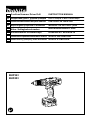
Makita BHP343 Manual de utilizare
- Categorie
- Burghie combinate fără fir
- Tip
- Manual de utilizare
Acest manual este potrivit și pentru

1
GB
Cordless Hammer Driver Drill INSTRUCTION MANUAL
UA
PL
Akumulatorowa wiertarko-wkrtarka udarowa
INSTRUKCJA OBSUGI
RO
Main de gurit i înurubat cu acumulatori
MANUAL DE INSTRUCIUNI
DE
Akku- Schla
g
bohrschraube
r
BEDIENUNGSANLEITUNG
HU
Akkumulátoros csavarbehajtó HASZNÁLATI KÉZIKÖNYV
SK
Akumulátorová pneumatická zarážacia vtaka
NÁVOD NA OBSLUHU
CZ
Akumulátorový píklepový vrtací šroubovák
NÁVOD K OBSLUZE
BHP343
BHP453

2
1
2
3
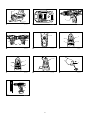
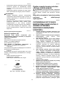
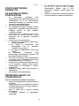
1 012153
1
2 012128
1
3 009084
A
B
1
4 009086
1
5 009079
8
6
10
1
2
3
4
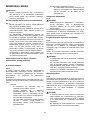
6 009087
8
6
10
1
2
3
4
7 009087
1
8 009088
1
9 002449
10 009085

3
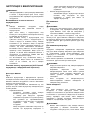
ENGLISH (Original instructions)
Explanation of general view
1-1. Red indicator
1-2. Button
1-3. Battery cartridge
2-1. Star marking
3-1. Switch trigger
4-1. Reversing switch lever
5-1. Speed change lever
6-1. Adjusting ring
6-2. Action mode changing ring
6-3. Graduation
6-4. Arrow
7-1. Adjusting ring
7-2. Action mode changing ring
7-3. Graduation
7-4. Arrow
8-1. Sleeve
9-1. Blow-out bulb
SPECIFICATIONS
Model BHP343 BHP453
Concrete 10 mm 13 mm
Steel 10 mm 13 mm
Wood 25 mm 36 mm
Wood screw 5.1 mm x 63 mm 6 mm x 75 mm
Capacities
Machine screw 6 mm
High (2) 0- 1,300
No load speed (min
-1
)
Low (1) 0 - 400
High (2) 0 - 19,500
Blows per minute (min
-1
)
Low (1) 0 - 6,000
Overall length 211 mm 232 mm
Net weight 1.4 Kg 1.7 Kg
Rated voltage D.C. 14.4 V D.C. 18 V
• Due to our continuing program of research and development, the specifications herein are subject to change without notice.
• Specifications and battery cartridge may differ from country to country.
• Weight, with battery cartridge, according to EPTA-Procedure 01/2003
ENE039-1
Intended use
The tool is intended for impact drilling in brick, concrete
and stone as well as for drilling without impact in wood,
metal, ceramic and plastic.
ENG905-1
Noise
The typical A-weighted noise level determined according
to EN60745:
Model BHP343
Sound pressure level (L
pA
) : 80 dB(A)
Uncertainty (K) : 3 dB(A)
The noise level under working may exceed 80 dB (A).
Model BHP453
Sound pressure level (L
pA
) : 83 dB(A)
Sound power level (L
WA
) : 94 dB(A)
Uncertainty (K) : 3 dB(A)
Wear ear protection
ENG900-1
Vibration
The vibration total value (tri-axial vector sum) determined
according to EN60745:
Model BHP343
Work mode: impact drilling into concrete
Vibration emission (a
h,ID
) : 10.0 m/s
2
Uncertainty (K) : 2.5 m/s
2
Work mode: drilling into metal
Vibration emission (a
h,D
) : 2.5 m/s
2
or less
Uncertainty (K) : 1.5 m/s
2
Model BHP453
Work mode: impact drilling into concrete
Vibration emission (a
h,ID
) : 10.0 m/s
2
Uncertainty (K) : 1.5 m/s
2
Work mode: drilling into metal
Vibration emission (a
h,D
) : 2.5 m/s
2
or less
Uncertainty (K) : 1.5 m/s
2
ENG901-1
•
The declared vibration emission value has been
measured in accordance with the standard test
method and may be used for comparing one tool
with another.
• The declared vibration emission value may also be
used in a preliminary assessment of exposure.

4
WARNING:
• The vibration emission during actual use of the
power tool can differ from the declared emission
value depending on the ways in which the tool is
used.
• Be sure to identify safety measures to protect the
operator that are based on an estimation of
exposure in the actual conditions of use (taking
account of all parts of the operating cycle such as
the times when the tool is switched off and when it
is running idle in addition to the trigger time).
ENH101-15
For European countries only
EC Declaration of Conformity
We Makita Corporation as the responsible
manufacturer declare that the following Makita
machine(s):
Designation of Machine:
Cordless Hammer Driver Drill
Model No./ Type: BHP343,BHP453
are of series production and
Conforms to the following European Directives:
2006/42/EC
And are manufactured in accordance with the following
standards or standardised documents:
EN60745
The technical documentation is kept by our authorised
representative in Europe who is:
Makita International Europe Ltd.
Michigan Drive, Tongwell,
Milton Keynes, Bucks MK15 8JD, England
30.1.2009
000230
Tomo ya su Kat o
Director
Makita Corporation
3-11-8, Sumiyoshi-cho,
Anjo, Aichi, 446-8502, JAPAN
GEA010-1
General Power Tool Safety
Warnings
WARNING Read all safety warnings and all
instructions. Failure to follow the warnings and
instructions may result in electric shock, fire and/or
serious injury.
Save all warnings and instructions for
future reference.
GEB056-4
CORDLESS HAMMER DRIVER
DRILL SAFETY WARNINGS
1. Wear ear protectors with impact drilling.
Exposure to noise can cause hearing loss.
2. Use auxiliary handle(s), if supplied with the
tool. Loss of control can cause personal injury.
3. Hold power tool by insulated gripping
surfaces, when performing an operation
where the cutting accessory may contact
hidden wiring. Cutting accessory contacting a
"live" wire may make exposed metal parts of the
power tool "live" and could give the operator an
electric shock.
4. Hold power tool by insulated gripping
surfaces, when performing an operation
where the fastener may contact hidden wiring.
Fasteners contacting a "live" wire may make
exposed metal parts of the power tool "live" and
could give the operator an electric shock.
5. Always be sure you have a firm footing.
Be sure no one is below when using the tool in
high locations.
6. Hold the tool firmly.
7. Keep hands away from rotating parts.
8. Do not leave the tool running. Operate the tool
only when hand-held.
9. Do not touch the bit or the workpiece
immediately after operation; they may be
extremely hot and could burn your skin.
10. Some material contains chemicals which may
be toxic. Take caution to prevent dust
inhalation and skin contact. Follow material
supplier safety data.
SAVE THESE INSTRUCTIONS.
WARNING:
DO NOT let comfort or familiarity with product
(gained from repeated use) replace strict adherence
to safety rules for the subject product. MISUSE or
failure to follow the safety rules stated in this
instruction manual may cause serious personal
injury.

5
ENC007-7
IMPORTANT SAFETY
INSTRUCTIONS
FOR BATTERY CARTRIDGE
1. Before using battery cartridge, read all
instructions and cautionary markings on (1)
battery charger, (2) battery, and (3) product
using battery.
2. Do not disassemble battery cartridge.
3. If operating time has become excessively
shorter, stop operating immediately. It may
result in a risk of overheating, possible burns
and even an explosion.
4. If electrolyte gets into your eyes, rinse them
out with clear water and seek medical
attention right away. It may result in loss of
your eyesight.
5. Do not short the battery cartridge:
(1) Do not touch the terminals with any
conductive material.
(2) Avoid storing battery cartridge in a
container with other metal objects such as
nails, coins, etc.
(3) Do not expose battery cartridge to water
or rain.
A battery short can cause a large current flow,
overheating, possible burns and even a
breakdown.
6. Do not store the tool and battery cartridge in
locations where the temperature may reach or
exceed 50 C (122 F).
7. Do not incinerate the battery cartridge even if
it is severely damaged or is completely worn
out. The battery cartridge can explode in a fire.
8. Be careful not to drop or strike battery.
9. Do not use a damaged battery.
SAVE THESE INSTRUCTIONS.
Tips for maintaining maximum battery life
1. Charge the battery cartridge before
completely discharged.
Always stop tool operation and charge the
battery cartridge when you notice less tool
power.
2. Never recharge a fully charged battery
cartridge.
Overcharging shortens the battery service life.
3. Charge the battery cartridge with room
temperature at 10 C - 40 C (50 F - 104 F).
Let a hot battery cartridge cool down before
charging it.
4. Charge the battery cartridge once in every six
months if you do not use it for a long period of
time.
FUNCTIONAL DESCRIPTION
CAUTION:
• Always be sure that the tool is switched off and the
battery cartridge is removed before adjusting or
checking function on the tool.
Installing or removing battery cartridge
Fig.1
• Always switch off the tool before installing or
removing of the battery cartridge.
• To r emove th e b at tery car tr idge, slid e i t fro m t he
tool while sliding the button on the front of the
cartridge.
• To in stall t he battery cartri dg e, align t he tongue on
the battery cartridge with the groove in the housing
and slip it into place. Always insert it all the way
until it locks in place with a little click. If you can see
the red indicator on the upper side of the button, it is
not locked completely. Install it fully until the red
indicator cannot be seen. If not, it may accidentally
fall out of the tool, causing injury to you or someone
around you.
• Do not use force when installing the battery
cartridge. If the cartridge does not slide in easily, it
is not being inserted correctly.
Battery protection system (Lithium-ion
battery with star marking)
For Model BHP453
Fig.2
Lithium-ion batteries with a star marking are equipped
with a protection system. This system automatically cuts
off power to the tool to extend battery life.
The tool will automatically stop during operation if the tool
and/or battery are placed under one of the following
conditions:
• Overloaded:
The tool is operated in a manner that causes
it to draw an abnormally high current.
In this situation, release the trigger switch on
the tool and stop the application that caused
the tool to become overloaded. Then pull the
trigger switch again to restart.
If the tool does not start, the battery is
overheated. In this situation, let the battery
cool before pulling the trigger switch again.
• Low battery voltage:
The remaining battery capacity is too low and
the tool will not operate. In this situation,
remove and recharge the battery.

6
Switch action
Fig.3
CAUTION:
• Before inserting the battery cartridge into the tool,
always check to see that the switch trigger actuates
properly and returns to the "OFF" position when
released.
To sta rt the t oo l, sim pl y pull the swi tc h trigge r. Too l s pe ed
is increased by increasing pressure on the switch trigger.
Release the switch trigger to stop.
Reversing switch action
Fig.4
This tool has a reversing switch to change the direction of
rotation. Depress the reversing switch lever from the A
side for clockwise rotation or from the B side for
counterclockwise rotation.
When the reversing switch lever is in the neutral position,
the switch trigger cannot be pulled.
CAUTION:
• Always check the direction of rotation before
operation.
• Use the reversing switch only after the tool comes
to a complete stop. Changing the direction of
rotation before the tool stops may damage the tool.
• When not operating the tool, always set the
reversing switch lever to the neutral position.
Speed change
Fig.5
To c hange the s pee d, fi rst sw itch off the tool and then
slide the speed change lever to the "2" side for high
speed or "1" side for low speed. Be sure that the speed
change lever is set to the correct position before
operation. Use the right speed for your job.
CAUTION:
•
Always set the speed change lever fully to the
correct position. If you operate the tool with the
speed change lever positioned halfway between the
"1" side and "2" side, the tool may be damaged.
• Do not use the speed change lever while the tool is
running. The tool may be damaged.
Selecting the action mode
Fig.6
This tool employs an action mode changing ring. Select
one of the three modes suitable for your work needs by
using this ring.
For rotation only, turn the ring so that the arrow on the
tool body points toward the
mark on the ring.
For rotation with hammering, turn the ring so that the
arrow points toward the
mark on the ring.
For rotation with clutch, turn the ring so that the arrow
points toward the
mark on the ring.
CAUTION:
• Always set the ring correctly to your desired mode
mark. If you operate the tool with the ring positioned
halfway between the mode marks, the tool may be
damaged.
Adjusting the fastening torque
Fig.7
The fastening torque can be adjusted in 16 steps by
turning the adjusting ring so that its graduations are
aligned with the arrow on the tool body. The fastening
torque is minimum when the number 1 is aligned with the
arrow, and maximum when the number 16 is aligned with
the arrow.
Before actual operation, drive a trial screw into your
material or a piece of duplicate material to determine
which torque level is required for a particular application.
ASSEMBLY
CAUTION:
• Always be sure that the tool is switched off and the
battery cartridge is removed before carrying out
any work on the tool.
Installing or removing driver bit or drill bit
Fig.8
Turn the sleeve counterclockwise to open the chuck jaws.
Place the bit in the chuck as far as it will go. Turn the
sleeve clockwise to tighten the chuck.
To re mo ve t he bit , turn t he sle eve count erclockw ise.
OPERATION
Hammer drilling operation
CAUTION:
• There is a tremendous and sudden twisting force
exerted on the tool/bit at the time of hole
break-through, when the hole becomes clogged
with chips and particles, or when striking reinforcing
rods embedded in the concrete.
First, turn the action mode changing ring so that the
arrow on the tool body points to the
marking. The
adjusting ring can be aligned in any torque levels for this
operation.
Be sure to use a tungsten-carbide tipped bit.
Position the bit at the desired location for the hole, then
pull the switch trigger. Do not force the tool. Light
pressure gives best results. Keep the tool in position and
prevent it from slipping away from the hole.
Do not apply more pressure when the hole becomes
clogged with chips or particles. Instead, run the tool at an
idle, then remove the bit partially from the hole. By
repeating this several times, the hole will be cleaned out
and normal drilling may be resumed.

7
Blow-out bulb (optional accessory)
Fig.9
After drilling the hole, use the blow-out bulb to clean the
dust out of the hole.
Screwdriving operation
Fig.10
First, turn the action mode changing ring so that the
arrow on the tool body points to the
marking. Adjust
the adjusting ring to the proper torque level for your work.
Then proceed as follows.
Place the point of the driver bit in the screw head and
apply pressure to the tool. Start the tool slowly and then
increase the speed gradually. Release the switch trigger
as soon as the clutch cuts in.
CAUTION:
• Make sure that the driver bit is inserted straight in
the screw head, or the screw and/or bit may be
damaged.
NOTE:
• When driving wood screws, predrill pilot holes to
make driving easier and to prevent splitting of the
workpiece. See the chart.
Nominal diameter of wood screw
(mm)
Recommended size of pilot hole
(mm)
3.1 2.0 - 2.2
3.5 2.2 - 2.5
3.8 2.5 - 2.8
4.5 2.9 - 3.2
4.8 3.1 - 3.4
5.1 3.3 - 3.6
5.5 3.7 - 3.9
5.8 4.0 - 4.2
6.1 4.2 - 4.4
006421
Drilling operation
First, turn the adjusting ring so that the pointer points to
the
marking. Then proceed as follows.
CAUTION:
•
Pressing excessively on the tool will not speed up
the drilling. In fact, this excessive pressure will only
serve to damage the tip of your bit, decrease the tool
performance and shorten the service life of the tool.
• There is a tremendous force exerted on the tool/bit
at the time of hole break through. Hold the tool
firmly and exert care when the bit begins to break
through the workpiece.
• A stuck bit can be removed simply by setting the
reversing switch to reverse rotation in order to back
out. However, the tool may back out abruptly if you
do not hold it firmly.
• Always secure small workpieces in a vise or similar
hold-down device.
• If the tool is operated continuously until the battery
cartridge has discharged, allow the tool to rest for
15 minutes before proceeding with a fresh battery.
Drilling in wood
When drilling in wood, the best results are obtained with
wood drills equipped with a guide screw. The guide
screw makes drilling easier by pulling the bit into the
workpiece.
Drilling in metal
To pre vent t he bit from s li pping w hen sta rting a ho le ,
make an indentation with a center-punch and hammer at
the point to be drilled. Place the point of the bit in the
indentation and start drilling.
Use a cutting lubricant when drilling metals. The
exceptions are iron and brass which should be drilled dry.
MAINTENANCE
CAUTION:
• Always be sure that the tool is switched off and the
battery cartridge is removed before attempting to
perform inspection or maintenance.
• Never use gasoline, benzine, thinner, alcohol or the
like. Discoloration, deformation or cracks may
result.
To maint ain produc t SA FETY an d RELIABI LI TY, re pa ir s,
any other maintenance or adjustment should be
performed by Makita Authorized Service Centers, always
using Makita replacement parts.
OPTIONAL ACCESSORIES
CAUTION:
• These accessories or attachments are
recommended for use with your Makita tool
specified in this manual. The use of any other
accessories or attachments might present a risk of
injury to persons. Only use accessory or
attachment for its stated purpose.
If you need any assistance for more details regarding
these accessories, ask your local Makita Service Center.
• Drill bits
• Tungsten-carbide tipped hammer bit
• Phillips bit
• Slotted bit
• Socket bit
• Blow-out bulb
• Safety goggles
• Various type of Makita genuine batteries and
chargers
• Rubber pad assembly
• Wool bonnet
• Foam polishing pad
• Plastic carrying case
NOTE:
• Some items in the list may be included in the tool
package as standard accessories. They may differ
from country to country.

8
( )
1-1.
1-2.
1-3.
2-1.
3-1.
4-1.
5-1.
6-1.
6-2.
6-3.
6-4.
7-1.
7-2.
7-3.
7-4.
8-1.
9-1.
BHP343 BHP453
10 13
10 13
25 36
5,1 x 63 6 x 75
6
(2) 0- 1300
(.
-1
)
(1) 0 - 400
(2) 0 - 19500
(.
-1
)
(1) 0 - 6000
211 232
1,4 1,7
14,4 . 18 .
• , ,
.
• .
• EPTA-Procedure 01/2003
ENE039-1
, ,
, , .
ENG905-1
,
EN60745:
BHP343
(L
pA
): 80 (A)
(): 3 (A)
80
(A).
BHP453
(L
pA
): 83 (A)
(L
WA
): 94 (A)
(K) : 3 (A)
ENG900-1
( )
EN60745:
BHP343
:
(a
,ID
) : 10,0 /
2
(): 2,5 /
2
:
(a
,D
) : 2,5 /
2
(): 1,5 /
2
BHP453
:
(a
,ID
) : 10,0 /
2
(): 1,5 /
2
:
(a
,D
) : 2,5 /
2
(): 1,5 /
2
ENG901-1
•

9
.
•
.
:
•
.
•
,
(
, ,
).
ENH101-15
, Makita Corporation,
, ,
Makita:
:
/ : BHP343,BHP453
:
2006/42/EC
:
EN60745
, :
Makita International Europe Ltd.
Michigan Drive, Tongwell,
Milton Keynes, Bucks MK15 8JD,
000230
Tomo ya su Kat o
Makita Corporation
3-11-8, Sumiyoshi-cho,
Anjo, Aichi, 446-8502,
GEA010-1
!
.
/ .
.
GEB056-4
-
1.
.
.
2. () (),
()
.
.
3.
,
.
.
4.
,
.
.
5. .
, .
6. .
7. ,
.
8. .
,
.
9.
,
.
10.
. ,
.
.
.

10
:
( );
.
, ,
.
ENC007-7
1.
,
(1)
, (2)
(3) ,
.
2. .
3. ,
.
,
.
4.
,
.
.
5. .
(1)
.
(2)
, ,
..
(3)
.
,
.
6.
,
50. C (122
F).
7.
,
.
.
8. .
9.
.
.
1.
, .
,
.
2.
.
.
3.
10 C - 40
C (50 F -
104 F).
.
4.
,
.

11
:
• , ,
,
.
.
Fig.1
•
.
• ,
,
.
• ,
.
.
,
, .
,
.
,
, .
• ,
.
, ,
.
(-
)
BHP453
Fig.2
-
.
.
, /
:
• :
.
,
.
,
.
,
, .
,
.
• :
,
.
.
.
Fig.3
:
• ,
,
,
".", .
, ,
.
.
.
-.
Fig.4
.
-
"",
- "".
-
, .
:
•
.
•
.
.
• ,
-
.
Fig.5
,
"2"
"1" . ,
, ,
.
, .
:
•
.
,

12
"1" "2",
.
•
, .
.
Fig.6
.
.
.
.
,
.
,
.
:
•
.
,
.
Fig.7
16
,
. ,
"1", -
"16".
, ,
,
,
.
:
•
, ,
, ,
- .
Fig.8
,
.
.
, .
, ,
.
:
•
/
,
,
.
,
.
- .
.
,
, .
.
.
,
.
,
.
,
.
, ,
.
( )
Fig.9
, ,
.
Fig.10
,
.
,
. .
.
, .
,
.
:
• ,
, /
.
:
•
. . .

13
Номінальний діаметр гвинта для деревини
(мм)
Рекомендований розмір напрямного отвору
(мм)
3,1 2,0 - 2,2
3,5 2,2 - 2,5
3,8 2,5 - 2,8
4,5 2,9 - 3,2
4,8 3,1 - 3,4
5,1 3,3 - 3,6
5,5 3,7 - 3,9
5,8 4,0 - 4,2
6,1 4,2 - 4,4
006421
,
.
.
:
•
.
,
.
•
/
.
,
.
• , , ,
, .
,
, .
•
.
• ,
,
, ,
15
.
,
.
, .
, .
.
- .
, .
:
• , ,
,
.
• , ,
, .
,
.
,
, ,
"",
"".
:
•
"",
.
.
.
,
"".
•
•
• Phillips
•
•
•
•
•
Makita
•
• '
•
•
:
•
.
.

14
POLSKI (Oryginalna instrukcja)
Objanienia do widoku ogólnego
1-1. Czerwony element
1-2. Przycisk
1-3. Akumulator
2-1. Znak gwiazdki
3-1. Spust przecznika
4-1. Dwignia przecznika obrotów
wstecznych
5-1. Dwignia zmiany prdkoci
6-1. Piercie regulacyjny
6-2. Piercie zmiany trybu pracy
6-3. Skala
6-4. Strzaka
7-1. Piercie regulacyjny
7-2. Piercie zmiany trybu pracy
7-3. Skala
7-4. Strzaka
8-1. Tuleja
9-1. Gruszka do przedmuchiwania
SPECYFIAKCJE
Model BHP343 BHP453
Beton 10 mm 13 mm
Stal 10 mm 13 mm
Drewno 25 mm 36 mm
Wkrt do drewna 5,1 mm x 63 mm 6 mm x 75 mm
Wydajno
Wkrt do elementów metalowych
6 mm
Wysoka (2) 0- 1300
Prdko bez obcienia
(min
-1
)
Niska (1) 0 - 400
Wysoka (2) 0 - 19500
Liczba udarów na minut
(min
-1
)
Niska (1) 0 - 6000
Dugo cakowita 211 mm 232 mm
Ciar netto 1,4 kg 1,7 kg
Napicie znamionowe Prd stay 14,4 V Prd stay 18 V
• W zwizku ze stale prowadzonym przez nasz firm programem badawczo-rozwojowym, niniejsze specyfikacje mog ulec zmianom
bez wczeniejszego powiadomienia.
• W innych krajach urzdzenie moe mie odmienne parametry techniczne I moe by wyposaone w inny akumulator.
• Waga urzdzenia wraz z akumulatorem obliczona zgodnie z procedur EPTA 01/2003
ENE039-1
Przeznaczenie
Narzdzie przeznaczone jest do wiercenia udarowego w
cegle, betonie i kamieniu, jak równie do wiercenia w
drewnie, metalu, ceramice i tworzywach sztucznych bez
uycia udaru.
ENG905-1
Poziom haasu i drga
Typowy równowany poziom dwiku A okrelony w
oparciu o EN60745:
Model BHP343
Poziom cinienia akustycznego (L
pA
): 80 dB(A)
Niepewno (K): 3 dB(A)
Poziom haasu podczas pracy moe przekracza 80 dB
(A).
Model BHP453
Poziom cinienia akustycznego (L
pA
): 83 dB(A)
Poziom mocy akustycznejl (L
WA
): 94 dB(A)
Niepewno (K): 3 dB(A)
Naley stosowa ochraniacze na uszy
ENG900-1
Drgania
Cakowita warto poziomu drga (suma wektorów w 3
osiach) okrelona zgodnie z norm EN60745:
Model BHP343
Tryb pracy: wiercenie udarowe w betonie
Emisja drga (a
h,ID
) : 10,0 m/s
2
Niepewno (K) : 2,5 m/s
2
Tryb pracy: wiercenie w metalu
Emisja drga (a
h,D
) : 2,5 m/s
2
lub poniej
Niepewno (K) : 1,5 m/s
2
Model BHP453
Tryb pracy: wiercenie udarowe w betonie
Emisja drga (a
h,ID
) : 10,0 m/s
2
Niepewno (K) : 1,5 m/s
2
Tryb pracy: wiercenie w metalu
Emisja drga (a
h,D
) : 2,5 m/s
2
lub poniej
Niepewno (K) : 1,5 m/s
2

15
ENG901-1
•
Deklarowana warto wytwarzanych drga zostaa
zmierzona zgodnie ze standardow metod
testow i mona j wykorzysta do porównywania
narzdzi.
• Deklarowan warto wytwarzanych drga mona
take wykorzysta we wstpnej ocenie naraenia.
OSTRZEENIE:
• Drgania wytwarzane podczas rzeczywistego
uytkowania elektronarzdzia mog si róni od
wartoci deklarowanej, w zalenoci od sposobu
jego uytkowania.
• W oparciu o szacowane naraenie w rzeczywistych
warunkach uytkowania naley okreli rodki
bezpieczestwa w celu ochrony operatora
(uwzgldniajc wszystkie elementy cyklu dziaania,
tj. czas, kiedy narzdzie jest wyczone i kiedy
pracuje na biegu jaowym, a take czas, kiedy jest
wczone).
ENH101-15
Dotyczy tylko krajów europejskich
Deklaracja zgodnoci UE
Niniejszym firma Makita Corporation jako
odpowiedzialny producent owiadcza, i opisywane
urzdzenie marki Makita:
Opis maszyny:
Akumulatorowa wiertarko-wkrtarka udarowa
Model nr/ Typ: BHP343,BHP453
jest produkowane seryjnie oraz
Jest zgodne z wymogami okrelonymi w
nastpujcych dyrektywach europejskich:
2006/42/EC
Jest produkowane zgodnie z nastpujcymi normami lub
dokumentami normalizacyjnymi:
EN60745
Dokumentacja techniczna przechowywana jest przez
naszego autoryzowanego przedstawiciela na Europ,
którym jest:
Makita International Europe Ltd.
Michigan Drive, Tongwell,
Milton Keynes, Bucks MK15 8JD, Anglia
000230
Tomo ya su Kat o
Dyrektor
Makita Corporation
3-11-8, Sumiyoshi-cho,
Anjo, Aichi, 446-8502, JAPONIA
GEA010-1
Ogólne zasady bezpieczestwa
obsugi elektronarzdzi
OSTRZEENIE Przeczytaj wszystkie ostrzeenia
i instrukcje. Nie przestrzeganie ich moe prowadzi do
porae prdem, poarów i/lub powanych obrae
ciaa.
Wszystkie ostrzeenia i instrukcje naley
zachowa do póniejszego
wykorzystania.
GEB056-4
OSTRZEENIA DOTYCZCE
BEZPIECZNEJ EKSPLOATACJI
AKUMULATOROWEJ
WIERTARKO-WKRTARKI
UDAROWEJ
1. Podczas uywania wiertatek udarowych no
ochraniacze na uszy. Haas moe spowodowa
utrat suchu.
2. Uywa narzdzia z dostarczonymi uchwytami
pomocniczymi. Utrata kontroli moe
spowodowa obraenia.
3. Gdy narzdzie podczas pracy moe zetkn
si z ukrytymi przewodami elektrycznymi,
naley trzyma urzdzenie za izolowane
uchwyty. Przecicie przewodu elektrycznego pod
napiciem powoduje, e równie odsonite
elementy metalowe narzdzia znajd si pod
napiciem, groc poraeniem operatora prdem
elektrycznym.
4. Gdy narzdzie podczas pracy moe zetkn
si z ukrytymi przewodami elektrycznymi,
naley trzyma
urzdzenie za izolowane
uchwyty. Zetknicie z przewodem elektrycznym
pod napiciem powoduje, e równie odsonite
elementy metalowe narzdzia znajd si pod
napiciem, groc poraeniem operatora prdem
elektrycznym.
5. Zapewni stae podoe.
Upewni si, czy nikt nie znajduje si poniej
miejsca pracy na wysokoci.
6. Narzdzie naley trzyma mocno i pewnie.
7. Trzyma rce z dala od czci obrotowych.
8. Nie pozostawia zaczonego elektronarzdzia.
Mona uruchomi elektronarzdzie tylko
wtedy, gdy jest trzymane w rkach.
9. Zaraz po zakoczeniu pracy nie wolno dotyka
wierta ani obrabianego elementu. Mog
one
by bardzo gorce, groc poparzeniem skóry.
10. Niektóre materiay zawieraj substancje
chemiczne, które mog by toksyczne. Unika
wdychania i kontaktu ze skór. Przestrzega
przepisów bezpieczestwa podanych przez

16
dostawc materiaów.
ZACHOWA INSTRUKCJE.
OSTRZEENIE:
NIE WOLNO pozwoli, aby wygoda lub rutyna
(nabyta w wyniku wielokrotnego uywania
narzdzia) zastpiy cise przestrzeganie zasad
bezpieczestwa obsugi. NIEWACIWE
UYTKOWANIE narzdzia lub niestosowanie si do
zasad bezpieczestwa podanych w niniejszej
instrukcji obsugi moe prowadzi do powanych
obrae ciaa.
ENC007-7
WANE ZASADY
BEZPIECZESTWA
DOTYCZCE AKUMULATORA
1. Przed uyciem akumulatora zapozna si z
wszystkimi zaleceniami i znakami
ostrzegawczymi na (1) adowarce, (2)
akumulatorze i (3) wyrobie, w którym bdzie
uywany akumulator.
2. Akumulatora nie wolno rozbiera.
3. Jeeli czas pracy uleg znacznemu skróceniu,
naley natychmiast przerwa prac. Moe
bowiem doj do przegrzania, ewentualnych
poparze, a nawet eksplozji.
4. W przypadku przedostania si elektrolitu do
oczu, przemy je wod i niezwocznie uzyska
pomoc lekarsk. Moe on bowiem
spowodowa utrat wzroku.
5. Nie doprowadza do zwarcia akumulatora:
(1) Nie dotyka styków przedmiotami
wykonanymi z materiaów
przewodzcych.
(2) Unika przechowywania akumulatora w
pojemniku z metalowymi przedmiotami,
typu gwodzie, monety itp.
(3) Chroni akumulator przed wod i
deszczem.
Zwarcie prowadzi do przepywu prdu
elektrycznego o du
ym nateniu i przegrzania
akumulatora, co w konsekwencji moe grozi
poparzeniami a nawet awari urzdzenia.
6. Narzdzia i akumulatora nie wolno
przechowywa w miejscach, w których
temperatura osiga bd przekracza 50 C
(122 F).
7. Akumulatorów nie wolno pali, równie tych
powanie uszkodzonych lub cakowicie
zuytych. W ogniu mog one bowiem
eksplodowa.
8. Chroni akumulator przed upadkiem i
uderzeniami.
9. Nie wolno uywa uszkodzonego
akumulatora.
ZACHOWA INSTRUKCJE.
Wskazówki dotyczce zachowania
maksymalnej trwaoci akumulatora
1. Akumulator naley naadowa zanim zostanie
do koca rozadowany.
Gdy zauwaysz spadek mocy narzdzia,
przerwij prac i naaduj akumulator.
2. Nie wolno adowa powtórnie w peni
naadowanego akumulatora.
Przeadowanie akumulatora skraca jego czas
eksploatacji.
3. Akumulator adowa w temperaturze
mieszczcej si w przedziale 10 C - 40 C
(50 F - 104 F). Gdy akumulator jest gorcy,
przed przystpieniem do jego adowania
odczeka, a ostygnie.
4. aduj akumulator raz na sze miesicy, jeli
nie uywasz urzdzenia przez dugi okres
czasu.

17
OPIS DZIAANIA
UWAGA:
• Przed przystpieniem do regulacji lub przegldu
narzdzia upewni si, czy jest ono wyczone i czy
zosta wyjty akumulator.
Wkadanie i wyjmowanie akumulatora
Rys.1
• Przed montaem lub demontaem akumulatora
naley wycza narzdzie
• Aby wyj akumulator, naley przesun przycisk
znajdujcy si w przedniej jego czci i wysun
akumulator.
• Aby woy akumulator, wystarczy wyrówna
wystp na akumulatorze z rowkiem w obudowie i
wsun go na swoje miejsce. Akumulator naley
wsuwa do oporu, a si zablokuje, co jest
sygnalizowane delikatnym klikniciem. Jeli jest
widoczny czerwony element w górnej czci
przycisku, akumulator nie zosta cakowicie
zablokowany. Naley go zamontowa cakowicie,
tak aby czerwony element przesta by widoczny.
W przeciwnym razie moe przypadkowo wypa z
narzdzia, ranic operatora lub osoby postronne.
• Przy montau akumulatora nie wolno uywa siy.
Jeli akumulator nie daje si swobodnie wsun,
prawdopodobnie zosta woony nieprawidowo.
System ochrony akumulatora (akumulator
litowo-jonowy ze znakiem gwiazdki)
Dla modelu BHP453
Rys.2
Akumulatory litowo-jonowe ze znakiem gwiazdki
posiadaj w system ochrony. System ten automatycznie
odcina dopyw prdu do narzdzia w celu wyduenia
ywotnoci akumulatora.
Narzdzie zostanie automatycznie zatrzymane podczas
pracy w nastpujcych sytuacjach zwizanych z
narzdziem/akumulatorem:
• Przecienie:
Narzdzie pracuje w sposób przyczyniajcy
si do niezwykle wysokiego wzrostu napicia.
W takiej sytuacji naley zwolni jzyk
spustowy narzdzia i zatrzyma wykonywan
prac, która doprowadzia do przecienia
narzdzia. Nastpnie pocign jzyk
spustowy w celu ponownego uruchomienia
narzdzia.
Jeeli narzdzie nie wczy si, akumulator
uleg przegrzaniu. W takiej sytuacji naley
poczeka, a akumulator ostygnie przed
ponownym pocigniciem za jzyk spustowy.
• Niskie napicie akumulatora:
Za niski poziom naadowania akumulatora,
aby narzdzie mogo pracowa. W takiej
sytuacji naley wyj akumulator i go
naadowa.
Wczanie
Rys.3
UWAGA:
• Przed woeniem akumulatora do narzdzia
zawsze sprawd, czy jzyk spustowy wycznika
dziaa prawidowo i po zwolnieniu powraca do
pooenia „OFF".
Aby uruchomi narzdzie, naley pocign za jzyk
spustowy przecznika. Prdko narzdzia ronie wraz
ze zwikszaniem nacisku na jzyk spustowy. W celu
zatrzymania urzdzenia wystarczy zwolni jzyk
spustowy przecznika.
Wczanie obrotów wstecznych.
Rys.4
Omawiane narzdzie jest wyposaone w przecznik
umoliwiajcy zmian kierunku obrotów. W celu
uzyskania obrotów zgodnych z ruchem wskazówek
zegara naley nacisn dwigni przecznika zmiany
kierunku obrotów po stronie A, natomiast by uzyska
obroty przeciwne do ruchu wskazówek zegara,
wystarczy nacisn dwigni przecznika po stronie B.
Gdy dwignia przecznika zmiany kierunku obrotów
znajduje si w pooeniu neutralnym, jzyk spustowy
przecznika jest zablokowany.
UWAGA:
• Przed uruchomieniem narzdzia naley zawsze
sprawdzi ustawienie kierunku obrotów.
• Kierunek obrotów mona zmienia tylko wówczas,
gdy urzdzenie cakowicie si zatrzyma. Zmiana
kierunku obrotów przed zatrzymaniem si
narzdzia grozi jego uszkodzeniem.
• Gdy narzdzie nie bdzie uywane, naley zawsze
ustawi dwigni przecznika zmiany kierunku
obrotów w pooeniu neutralnym.
Zmiana prdkoci
Rys.5
Aby zmieni prdko, najpierw wycz narzdzie, a
nastpnie przesu dwigni zmiany prdkoci do pozycji
„2", aby uzyska wysok prdko, lub do pozycji „1",
aby uzyska nisk prdko. Przed przystpieniem do
pracy upewnij si, czy dwignia zmiany prdkoci
obrotowej jest ustawiona we waciwej pozycji. Do
wykonania konkretnego zadania uywaj waciwej
prdkoci.
UWAGA:
• Dwigni zmiany prdkoci naley zawsze
ustawia dokadnie w wybranej pozycji. W
przypadku uruchomienia narzdzia przy dwigni
zmiany prdkoci ustawionej w poowie midzy
pozycj „1" i „2" moe doj do uszkodzenia
narzdzia.

18
• Nie wolno korzysta z dwigni zmiany prdkoci,
gdy narzdzie jest w ruchu. Narzdzie moe
bowiem ulec uszkodzeniu.
Wybór trybu pracy
Rys.6
W tym narzdziu zastosowano piercie zmiany trybu
pracy. Pozwala on wybra sporód trzech trybów jeden
odpowiedni do potrzeb danego zadania.
W celu wczenia ruchu obrotowego naley obróci
piercie tak, aby strzaka na korpusie narzdzia
wskazywaa symbol
na piercieniu.
W celu wczenia wiercenia udarowego naley obróci
piercie w taki sposób, aby strzaka na korpusie
narzdzia wskazywaa symbol
na piercieniu.
W celu wczenia ruchu obrotowego ze sprzgem
naley obróci piercie w taki sposób, aby strzaka na
korpusie narzdzia wskazywaa symbol
na
piercieniu.
UWAGA:
• Piercie powinien by zawsze precyzyjnie
ustawiony w pozycji symbolu odpowiadajcego
wybranemu trybowi pracy. W przypadku
uruchomienia narzdzia, gdy piercie ustawiony
jest midzy symbolami trybu pracy, moe doj do
uszkodzenia narzdzia.
Regulacja momentu dokrcania
Rys.7
Moment dokrcania mona regulowa w zakresie 16
ustawie poprzez obrót piercienia regulacyjnego w taki
sposób, aby waciwe ustawienie na piercieniu znalazo
si w jednej linii ze strzak na obudowie narzdzia.
Moment dokrcania ma warto minimaln, gdy strzaka
wskazuje numer 1, a maksymaln po wyrównaniu
strzaki z numerem 16.
Przed przystpieniem do pracy naley przeprowadzi
prób wkrcania w dany element lub inny element z tego
samego materiau, aby ustali poziom momentu
obrotowego wymagany w danym zastosowaniu.
MONTA
UWAGA:
• Przed przystpieniem do jakichkolwiek czynnoci
zwizanych z obsug narzdzia naley koniecznie
upewni si, czy jest ono wyczone i czy
akumulator zosta wyjty.
Monta i demonta tradycyjnej kocówki do
wkrcania lub kocówki nasadowej
Rys.8
Obró tulej w kierunku przeciwnym do ruchu
wskazówek zegara, aby rozsun szczki uchwytu.
Wsu wierto do oporu do uchwytu wiertarskiego. Obró
tulej w kierunku zgodnym z ruchem wskazówek zegara,
aby zacisn uchwyt.
W celu wyjcia wierta obró tulej w kierunku
przeciwnym do ruchu wskazówek zegara.
DZIAANIE
Operacja wiercenia z uyciem udaru
UWAGA:
• W momencie przewiercania otworu, gdy otwór
zapchany jest wiórami, opikami lub gruzem lub w
przypadku natknicia si na prty zbrojeniowe
osadzone w betonie na narzdzie/wierto
wywierana jest nagle olbrzymia sia skrcajca.
Najpierw naley obróci piercie zmiany trybu pracy w
takie pooenie, aby strzaka na korpusie narzdzia
wskazywaa symbol
. Za pomoc piercienia
regulacyjnego mona ustawi dowoln warto
momentu wymaganego do wykonania danej operacji.
Naley koniecznie uywa wierta z kocówk z wglika
wolframu.
Ustawi wierto w wybranym miejscu, gdzie ma by
wywiercony otwór, a nastpnie pocign za jzyk
spustowy przecznika. Nie przecia narzdzia. Lekki
nacisk daje najlepsze wyniki. Trzyma narzdzie w
jednej pozycji uwaajc, aby wierto nie lizgao si i nie
przesuwao si wzgldem otworu.
Nie zwiksza nacisku, gdy otwór zapcha si wiórami,
opikami lub gruzem. Zamiast tego pozwól, aby
narzdzie pracowao przez chwil bez obcienia, a
nastpnie wyci
gnij wierto czciowo z otworu. Po
kilkakrotnym powtórzeniu tej procedury otwór zostanie
oczyszczony i mona wznowi normaln operacj
wiercenia.
Gruszka do przedmuchiwania (wyposaenie
dodatkowe)
Rys.9
Po wywierceniu otworu mona skorzysta z gruszki do
przedmuchiwania, aby oczyci otwór z pyu.
Operacja wkrcania
Rys.10
Najpierw naley obróci piercie zmiany trybu pracy w
takie pooenie, aby strzaka na korpusie narzdzia
wskazywaa symbol
. Ustaw piercie regulacyjny w
pozycji odpowiadajcej waciwemu dla danej operacji
momentowi. Nastpnie postpuj zgodnie z poniszym
opisem.
Wsu ostrze kocówki do wkrcania do gniazda we bie
wkrtu i docinij narzdzie. Uruchom powoli narzdzie, a
nastpnie stopniowo zwikszaj prdko. Gdy tylko
sprzgo zadziaa, zwolnij jzyk spustowy przecznika.
UWAGA:
• Kocówka do wkrcania powinna by prostopada
do ba wkrtu, w przeciwnym razie wkrt i/lub
kocówka mog ulec uszkodzeniu.

19
UWAGA:
• W przypadku osadzania wkrtów w drewnie naley
wczeniej ponawierca otwory prowadzce.
Uatwiaj one wkrcanie i zapobiegaj pkaniu
elementu. Zapoznaj si z tabel.
Nominalna średnica wkrętu do drewna
(mm)
Zalecany rozmiar otworu prowadzącego
(mm)
3,1 2,0 - 2,2
3,5 2,2 - 2,5
3,8 2,5 - 2,8
4,5 2,9 - 3,2
4,8 3,1 - 3,4
5,1 3,3 - 3,6
5,5 3,7 - 3,9
5,8 4,0 - 4,2
6,1 4,2 - 4,4
006421
Wiercenie otworów
Najpierw obró piercie regulacyjny tak, aby strzaka
wskazywaa znak
. Nastpnie postpuj zgodnie z
poniszym opisem.
UWAGA:
• Wywieranie nadmiernego nacisku na narzdzie nie
przyspiesza wiercenia. W praktyce, wywieranie
nadmiernego nacisku przyczynia si jedynie do
uszkodzenia kocówki wierta, zmniejszenia
wydajnoci i skrócenia okresu eksploatacyjnego
narzdzia.
• W momencie przebijania otworu na
narzdzie/wierto wywierana jest olbrzymia sia.
Gdy wierto zaczyna przebija na wylot otwór w
elemencie, naley zachowa ostrono i mocno
trzyma narzdzie.
•
Zablokowane wierto mona atwo wyj, zaczajc
przecznik wstecznych obrotów i wyprowadzajc
wierto. Elektronarzdzie moe jednak nagle odbi,
jeli nie zostanie mocno przytrzymane.
• Niewielkie obrabiane kawaki materiau zawsze
zamocowywa w imadle lub podobnym przyrzdzie
przytrzymujcym.
• Jeeli narzdzie jest uywane bez przerwy a do
rozadowania akumulatora, naley je odstawi na
15 minut, zanim praca zostanie podjta na nowo z
uyciem innego naadowanego akumulatora.
Wiercenie w drewnie
Podczas wiercenia w drewnie najlepsze wyniki osiga
si wkrtami do drewna ze rub prowadzc. ruba
prowadzca uatwia wiercenie dziki naprowadzeniu
wierta w obrabiany materia.
Wiercenie w metalu
Dla uniknicia zelizgnicia si wierta przy
rozpoczynaniu wiercenia, napunktowa miejsce otworu
przy pomocy punktaka i motka. Umieci kocówk
wierta we wgbieniu i rozpocz wiercenie.
Stosowa rodki smarujco-chodzce przy wierceniu w
metalu. Wyjtki stanowi
elazo i mied, które naley
wierci na sucho.
KONSERWACJA
UWAGA:
• Przed przystpieniem do przegldu narzdzia lub
jego konserwacji upewni si, czy jest ono
wyczone i czy akumulator zosta wyjty.
• Nie wolno uywa benzyny, benzenu,
rozpuszczalnika, alkoholu itp. Substancje takie
mog spowodowa odbarwienia, odksztacenia lub
pknicia.
Dla zachowania BEZPIECZESTWA i
NIEZAWODNOCI wyrobu, naprawy oraz inne prace
konserwacyjne i regulacyjne powinny by wykonywane
przez Autoryzowane Centra Serwisowe Makita,
wycznie przy uyciu czci zamiennych Makita.
AKCESORIA OPCJONALNE
UWAGA:
• Zaleca si stosowanie wymienionych akcesoriów i
dodatków razem z elektronarzdziem Makita
opisanym w niniejszej instrukcji. Stosowanie
jakichkolwiek innych akcesoriów i dodatków moe
stanowi ryzyko uszkodzenia ciaa. Stosowa
akcesoria i dodatki w celach wycznie zgodnych z
ich przeznaczeniem.
W razie potrzeby, wszelkiej pomocy i szczegóowych
informacji na temat niniejszych akcesoriów udziel
Pastwu lokalne Centra Serwisowe Makita.
• Wierta
• Wierto udarowe z kocówk z wglika wolframu
• Kocówka krzyowa
• Kocówka paska
• Kocówka nasadowa
• Gruszka do przedmuchiwania
• Gogle ochronne
• Róne typy oryginalnych akumulatorów i adowarek
marki Makita
• Gumowa tarcza szlifierska
• Nakadka weniana
• Piankowa tarcza polerska
• Walizka z tworzywa sztucznego
UWAGA:
• Niektóre pozycje znajdujce si na licie mog by
doczone do pakietu narzdziowego jako
akcesoria standardowe. Mog to by róne pozycje,
w zalenoci od kraju.

20
ROMÂN (Instruciuni originale)
Explicitarea vederii de ansamblu
1-1. Indicator rou
1-2. Buton
1-3. Cartuul acumulatorului
2-1. Marcaj în stea
3-1. Trgaciul întreruptorului
4-1. Levier de inversor
5-1. Pârghie de schimbare a vitezei
6-1. Inel de reglare
6-2. Inel de schimbare a modului de
acionare
6-3. Gradaie
6-4. Sgeat
7-1. Inel de reglare
7-2. Inel de schimbare a modului de
acionare
7-3. Gradaie
7-4. Sgeat
8-1. Manon
9-1. Par de suflare
SPECIFICAII
Model BHP343 BHP453
Beton 10 mm 13 mm
Oel 10 mm 13 mm
Lemn 25 mm 36 mm
urub pentru lemn 5,1 mm x 63 mm 6 mm x 75 mm
Capaciti
urub cu cap 6 mm
Înalt (2) 0- 1.300
Turaia în gol (min
-1
)
Redus (1) 0 - 400
Înalt (2) 0 - 19.500
Lovituri pe minut (min
-1
)
Redus (1) 0 - 6.000
Lungime total 211 mm 232 mm
Greutate net 1,4 kg 1,7 kg
Tensiu ne no mina l 14,4 V cc. 18 V cc.
• Datorit programului nostru continuu de cercetare i dezvoltare, caracteristicile pot fi modificate fr o notificare prealabil.
• Specificaiile i ansamblul baterie pot diferi de la ar la ar.
• Greutatea, cu ansamblul baterie, conform procedurii EPTA 01/2003
ENE039-1
Destinaia de utilizare
Maina este destinat guririi cu percuie în crmid,
beton i piatr precum i guririi fr percuie în lemn,
metal, ceramic i plastic.
ENG905-1
Emisie de zgomot
Nivelul de zgomot normal ponderat A determinat în
conformitate cu EN60745:
Model BHP343
Nivel de presiune acustic (L
pA
): 80 dB(A)
Eroare (K): 3 dB (A)
Nivelul de zgomot în lucru poate depi 80 dB (A).
Model BHP453
Nivel de presiune acustic (L
pA
): 83 dB(A)
Nivel putere sonor (L
WA
): 94 dB(A)
Eroare (K): 3 dB(A)
Purtai mijloace de protecie a auzului
ENG900-1
Vibraii
Valoarea total a vibraiilor (suma vectorilor tri-axiali)
determinat conform EN60745:
Model BHP343
Mod de funcionare: gurire cu percuie în beton
Nivel de vibraii (a
h,ID
): 10,0 m/s
2
Incertitudine (K): 2,5 m/s
2
Mod de funcionare: gurire în metal
Nivel de vibraii (a
h,D
): 2,5 m/s
2
sau mai puin
Incertitudine (K): 1,5 m/s
2
Model BHP453
Mod de funcionare: gurire cu percuie în beton
Nivel de vibraii (a
h,ID
): 10,0 m/s
2
Incertitudine (K): 1,5 m/s
2
Mod de funcionare: gurire în metal
Nivel de vibraii (a
h,D
): 2,5 m/s
2
sau mai puin
Incertitudine (K): 1,5 m/s
2
Pagina se încarcă...
Pagina se încarcă...
Pagina se încarcă...
Pagina se încarcă...
Pagina se încarcă...
Pagina se încarcă...
Pagina se încarcă...
Pagina se încarcă...
Pagina se încarcă...
Pagina se încarcă...
Pagina se încarcă...
Pagina se încarcă...
Pagina se încarcă...
Pagina se încarcă...
Pagina se încarcă...
Pagina se încarcă...
Pagina se încarcă...
Pagina se încarcă...
Pagina se încarcă...
Pagina se încarcă...
Pagina se încarcă...
Pagina se încarcă...
Pagina se încarcă...
Pagina se încarcă...
Pagina se încarcă...
Pagina se încarcă...
Pagina se încarcă...
Pagina se încarcă...
-
 1
1
-
 2
2
-
 3
3
-
 4
4
-
 5
5
-
 6
6
-
 7
7
-
 8
8
-
 9
9
-
 10
10
-
 11
11
-
 12
12
-
 13
13
-
 14
14
-
 15
15
-
 16
16
-
 17
17
-
 18
18
-
 19
19
-
 20
20
-
 21
21
-
 22
22
-
 23
23
-
 24
24
-
 25
25
-
 26
26
-
 27
27
-
 28
28
-
 29
29
-
 30
30
-
 31
31
-
 32
32
-
 33
33
-
 34
34
-
 35
35
-
 36
36
-
 37
37
-
 38
38
-
 39
39
-
 40
40
-
 41
41
-
 42
42
-
 43
43
-
 44
44
-
 45
45
-
 46
46
-
 47
47
-
 48
48


Makita BHP343 Manual de utilizare
- Categorie
- Burghie combinate fără fir
- Tip
- Manual de utilizare
- Acest manual este potrivit și pentru
în alte limbi
- slovenčina: Makita BHP343 Používateľská príručka
- polski: Makita BHP343 Instrukcja obsługi
- Deutsch: Makita BHP343 Benutzerhandbuch
Lucrări înrudite
-
Makita DHP483 Cordless Hammer Driver Drill Manual de utilizare
-
Makita BHP456 Manual de utilizare
-
-
Makita HP488D Manual de utilizare
-
Makita DHP482 Manual de utilizare
-
-
Makita DHP482ZW Manual de utilizare
-
-
-