Makita DHP482 Manual de utilizare
- Categorie
- Burghie combinate fără fir
- Tip
- Manual de utilizare

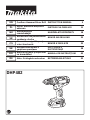
DHP482
EN Cordless Hammer Driver Drill INSTRUCTION MANUAL 5
PL Akum. wiertarko-wkrętarka
udarowa INSTRUKCJA OBSŁUGI 11
HU Akkumulátoros
csavarbehajtó HASZNÁLATI KÉZIKÖNYV 18
SK Akumulátorová pneumatická
zarážacia vŕtačka NÁVOD NA OBSLUHU 25
CS Akumulátorový příklepový
vrtací šroubovák NÁVOD K OBSLUZE 32
UK Бездротовий дриль з
ударним приводом
ІНСТРУКЦІЯ З
ЕКСПЛУАТАЦІЇ 38
RO Maşină de găurit şi înşurubat
cu acumulatori MANUAL DE INSTRUCŢIUNI 45
DE Akku- Schlagbohrschrauber BETRIEBSANLEITUNG 52

2
3
1
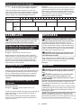
Fig.1
1
Fig.2
1
2
Fig.3
1
Fig.4
1
Fig.5
1
AA
AB
Fig.6
1
Fig.7
1
2
3
4
Fig.8
2

1
2
3
4
Fig.9
2
3
1
Fig.10
2
1
3
Fig.11
2
1
Fig.12
Fig.13
1
Fig.14
1
Fig.15
1
2
Fig.16
3

1
23
Fig.17
1
Fig.18
2
1
Fig.19
1
2
Fig.20
4

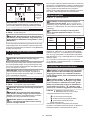
5ENGLISH
ENGLISH (Original instructions)
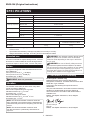
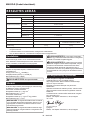
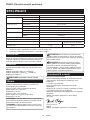
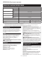
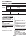
SPECIFICATIONS
Model: DHP482
Drilling capacities Concrete 13 mm
Steel 13 mm
Wood 38 mm
Fastening capacities Wood screw 10 mm x 90 mm
Machine screw M6
No load speed High (2) 0 - 1,900 min-1
Low (1) 0 - 600 min-1
Blows per minute High (2) 0 - 28,500 min-1
Low (1) 0 - 9,000 min-1
Overall length 198 mm
Rated voltage D.C. 18 V
Battery cartridge BL1815N, BL1820, BL1820B BL1830, BL1840, BL1850, BL1830B,
BL1840B, BL1850B, BL1860B
Net weight 1.5 kg 1.8 kg
• Due to our continuing program of research and development, the specications herein are subject to change
without notice.
• Specications and battery cartridge may differ from country to country.
• Weight, with battery cartridge, according to EPTA-Procedure 01/2003
Intended use
The tool is intended for impact drilling in brick, concrete
and stone. It is also suitable for screw driving and drill-
ing without impact in wood, metal, ceramic and plastic.
Noise
The typical A-weighted noise level determined accord-
ing to EN60745:
Sound pressure level (LpA):82 dB(A)
Sound power level (LWA):93 dB (A)
Uncertainty (K) :3dB(A)
WARNING: Wear ear protection.
Vibration
The vibration total value (tri-axial vector sum) deter-
mined according to EN60745:
Work mode: impact drilling into concrete
Vibration emission (ah,ID):6.0 m/s2
Uncertainty (K) :1.5 m/s2
Work mode: drilling into metal
Vibration emission (ah,D):2.5 m/s2 or less
Uncertainty (K) :1.5 m/s2
NOTE: The declared vibration emission value has
been measured in accordance with the standard test
method and may be used for comparing one tool with
another.
NOTE: The declared vibration emission value
may also be used in apreliminary assessment of
exposure.
WARNING: The vibration emission during actual
use of the power tool can differ from the declared
emission value depending on the ways in which the
tool is used.
WARNING: Be sure to identify safety measures
to protect the operator that are based on an estima-
tion of exposure in the actual conditions of use (taking
account of all parts of the operating cycle such as
the times when the tool is switched off and when it is
running idle in addition to the trigger time).
EC Declaration of Conformity
For European countries only
Makita declares that the following Machine(s):
Designation of Machine: Cordless Hammer Driver Drill
Model No./ Type: DHP482
Conforms to the following European Directives:
2006/42/EC
They are manufactured in accordance with the following
standard or standardized documents: EN60745
The technical le in accordance with 2006/42/EC is
available from:
Makita, Jan-Baptist Vinkstraat 2, 3070, Belgium
30.3.2015
Yasushi Fukaya
Director
Makita, Jan-Baptist Vinkstraat 2, 3070, Belgium

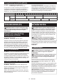
6ENGLISH
General power tool safety warnings
WARNING: Read all safety warnings and
all instructions. Failure to follow the warnings and
instructions may result in electric shock, re and/or
serious injury.
Save all warnings and instruc-
tions for future reference.
The term "power tool" in the warnings refers to your
mains-operated (corded) power tool or battery-operated
(cordless) power tool.
Cordless hammer driver drill safety
warnings
1. Wear ear protectors when impact drilling.
Exposure to noise can cause hearing loss.
2. Use auxiliary handle(s), if supplied with the
tool. Loss of control can cause personal injury.
3. Hold power tool by insulated gripping sur-
faces, when performing an operation where
the cutting accessory may contact hidden
wiring. Cutting accessory contacting a"live"
wire may make exposed metal parts of the power
tool "live" and could give the operator an electric
shock.
4. Hold power tool by insulated gripping sur-
faces, when performing an operation where
the fastener may contact hidden wiring.
Fasteners contacting a"live" wire may make
exposed metal parts of the power tool "live" and
could give the operator an electric shock.
5. Always be sure you have a rm footing. Be
sure no one is below when using the tool in
high locations.
6. Hold the tool rmly.
7. Keep hands away from rotating parts.
8. Do not leave the tool running. Operate the tool
only when hand-held.
9. Do not touch the bit or the workpiece immedi-
ately after operation; they may be extremely
hot and could burn your skin.
10. Some material contains chemicals which may
be toxic. Take caution to prevent dust inhala-
tion and skin contact. Follow material supplier
safety data.
SAVE THESE INSTRUCTIONS.
WARNING: DO NOT let comfort or familiarity
with product (gained from repeated use) replace
strict adherence to safety rules for the subject
product. MISUSE or failure to follow the safety
rules stated in this instruction manual may cause
serious personal injury.
Important safety instructions for
battery cartridge
1.
Before using battery cartridge, read all instruc-
tions and cautionary markings on (1) battery
charger, (2) battery, and (3) product using battery.
2. Do not disassemble battery cartridge.
3. If operating time has become excessively
shorter, stop operating immediately. It may
result in a risk of overheating, possible burns
and even an explosion.
4.
If electrolyte gets into your eyes, rinse them out
with clear water and seek medical attention right
away. It may result in loss of your eyesight.
5. Do not short the battery cartridge:
(1) Do not touch the terminals with any con-
ductive material.
(2) Avoid storing battery cartridge in a con-
tainer with other metal objects such as
nails, coins, etc.
(3)
Do not expose battery cartridge to water or rain.
A battery short can cause a large current
ow, overheating, possible burns and even a
breakdown.
6. Do not store the tool and battery cartridge in
locations where the temperature may reach or
exceed 50 °C (122 °F).
7. Do not incinerate the battery cartridge even if
it is severely damaged or is completely worn
out. The battery cartridge can explode in a re.
8. Be careful not to drop or strike battery.
9. Do not use a damaged battery.
10.
The contained lithium-ion batteries are subject to
the Dangerous Goods Legislation requirements.
For commercial transports e.g. by third parties,
forwarding agents, special requirement on pack-
aging and labeling must be observed.
For preparation of the item being shipped, consult-
ing an expert for hazardous material is required.
Please also observe possibly more detailed
national regulations.
Tape or mask off open contacts and pack up the
battery in such amanner that it cannot move
around in the packaging.
11. Follow your local regulations relating to dis-
posal of battery.
SAVE THESE INSTRUCTIONS.
CAUTION:
Only use genuine Makita batteries.
Use of non-genuine Makita batteries, or batteries that
have been altered, may result in the battery bursting
causing res, personal injury and damage. It will also
void the Makita warranty for the Makita tool and charger.
Tips for maintaining maximum
battery life
1. Charge the battery cartridge before completely
discharged. Always stop tool operation and
charge the battery cartridge when you notice
less tool power.
2. Never recharge a fully charged battery car-
tridge. Overcharging shortens the battery
service life.
3. Charge the battery cartridge with room tem-
perature at 10 °C - 40 °C (50 °F - 104 °F). Let
a hot battery cartridge cool down before
charging it.
4. Charge the battery cartridge if you do not use
it for a long period (more than six months).

7ENGLISH
FUNCTIONAL
DESCRIPTION
CAUTION: Always be sure that the tool is
switched off and the battery cartridge is removed
before adjusting or checking function on the tool.
Installing or removing battery
cartridge
CAUTION: Always switch off the tool before
installing or removing of the battery cartridge.
CAUTION: Hold the tool and the battery car-
tridge rmly when installing or removing battery
cartridge. Failure to hold the tool and the battery
cartridge rmly may cause them to slip off your hands
and result in damage to the tool and battery cartridge
and apersonal injury.
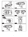
►Fig.1: 1. Red indicator 2. Button 3. Battery cartridge
To remove the battery cartridge, slide it from the tool
while sliding the button on the front of the cartridge.
To install the battery cartridge, align the tongue on the
battery cartridge with the groove in the housing and slip
it into place. Insert it all the way until it locks in place
with a little click. If you can see the red indicator on the
upper side of the button, it is not locked completely.
CAUTION: Always install the battery cartridge
fully until the red indicator cannot be seen. If not,
it may accidentally fall out of the tool, causing injury to
you or someone around you.
CAUTION: Do not install the battery cartridge
forcibly. If the cartridge does not slide in easily, it is
not being inserted correctly.
Battery protection system
Lithium-ion battery with star marking
►Fig.2: 1. Star marking
Lithium-ion batteries with astar marking are equipped
with aprotection system. This system automatically
cuts off power to the tool to extend battery life.
The tool will automatically stop during operation if the
tool and/or battery are placed under one of the following
conditions:
Overloaded:
The tool is operated in amanner that causes it to draw
an abnormally high current.
In this situation, turn the tool off and stop the application
that caused the tool to become overloaded. Then turn
the tool on to restart.
If the tool does not start, the battery is overheated. In
this situation, let the battery cool before turning the tool
on again.
Low battery voltage:
The remaining battery capacity is too low and the tool
will not operate. In this situation, remove and recharge
the battery.
Indicating the remaining battery
capacity
Only for battery cartridges with "B" at the end of the
model number
►Fig.3: 1. Indicator lamps 2. Check button
Press the check button on the battery cartridge to indi-
cate the remaining battery capacity. The indicator lamps
light up for few seconds.
Indicator lamps Remaining
capacity
Lighted Off Blinking
75% to 100%
50% to 75%
25% to 50%
0% to 25%
Charge the
battery.
The battery
may have
malfunctioned.
NOTE: Depending on the conditions of use and the
ambient temperature, the indication may differ slightly
from the actual capacity.
Switch action
►Fig.4: 1. Switch trigger
CAUTION: Before installing the battery car-
tridge into the tool, always check to see that the
switch trigger actuates properly and returns to
the "OFF" position when released.
To start the tool, simply pull the switch trigger. Tool
speed is increased by increasing pressure on the switch
trigger. Release the switch trigger to stop.
Lighting up the front lamp
►Fig.5: 1. Lamp
CAUTION: Do not look in the light or see the
source of light directly.
Pull the switch trigger to light up the lamp. The lamp
keeps on lighting while the switch trigger is being pulled.
The lamp goes out 10 -15 seconds after releasing the
trigger.
NOTE: Use a dry cloth to wipe the dirt off the lens of
the lamp. Be careful not to scratch the lens of lamp, or
it may lower the illumination.

8ENGLISH
Reversing switch action
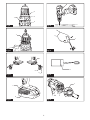
►Fig.6: 1. Reversing switch lever
CAUTION: Always check the direction of
rotation before operation.
CAUTION: Use the reversing switch only after
the tool comes to a complete stop. Changing the
direction of rotation before the tool stops may dam-
age the tool.
CAUTION: When not operating the tool,
always set the reversing switch lever to the neu-
tral position.
This tool has areversing switch to change the direction
of rotation. Depress the reversing switch lever from the
Aside for clockwise rotation or from the Bside for coun-
terclockwise rotation.
When the reversing switch lever is in the neutral posi-
tion, the switch trigger cannot be pulled.
Speed change
►Fig.7: 1. Speed change lever
CAUTION: Always set the speed change lever
fully to the correct position. If you operate the
tool with the speed change lever positioned halfway
between the "1" side and "2" side, the tool may be
damaged.
CAUTION: Do not use the speed change lever
while the tool is running. The tool may be damaged.
Position of
speed
change lever
Speed Torque Applicable
operation
1Low High Heavy load-
ing operation
2High Low Light loading
operation
To change the speed, switch off the tool rst. Select
the "2" side for high speed or "1" for low speed but high
torque. Be sure that the speed change lever is set to the
correct position before operation.
If the tool speed is coming down extremely during the
operation with "2", slide the lever to the "1" and restart
the operation.
Selecting the action mode
CAUTION: Always set the ring correctly to
your desired mode mark. If you operate the tool
with the ring positioned halfway between the
mode marks, the tool may be damaged.
CAUTION: When you change the position
from " " to other modes, it may be a little dif-
culty to slide the action mode changing ring. In
this case, switch on and run the tool for a second
at the " " position, then stop the tool and slide
the ring to your desired position.
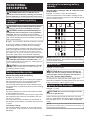
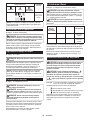
►Fig.8: 1. Action mode changing ring 2. Adjusting
ring 3. Graduation 4. Arrow
This tool has three action modes.
• Drilling mode (rotation only)
• Hammer drilling mode (rotation with
hammering)
• Screwdriving mode (rotation with clutch)
Select one mode suitable for your work. Turn the
action mode changing ring and align the mark that you
selected with the arrow on the tool body.
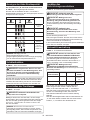
Adjusting the fastening torque
►Fig.9: 1. Action mode changing ring 2. Adjusting
ring 3. Graduation 4. Arrow
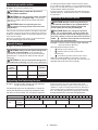
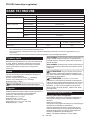
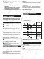
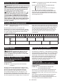
The fastening torque can be adjusted in 21 steps by
turning the adjusting ring. Align the graduations with
the arrow on the tool body. You can get the minimum
fastening torque at 1 and maximum torque at 21.
Before actual operation, drive a trial screw into your
material or a piece of duplicate material to determine
which torque level is required for a particular applica-
tion. The following shows the rough guide of the rela-
tionship between the screw size and graduation.
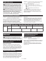
Graduation 12345678910 11 12 13 14 15 16 17 18 19 20 21
Machine screw M4 M5 M6
Wood
screw Soft wood
(e.g. pine) –ɸ3.5 x 22 ɸ4.1x 38 –
Hard wood
(e.g. lauan) –ɸ3.5 x 22 ɸ4.1x 38 –

9ENGLISH
ASSEMBLY
CAUTION: Always be sure that the tool is
switched off and the battery cartridge is removed
before carrying out any work on the tool.
Installing or removing driver bit/
drill bit
Optional accessory
►Fig.10: 1. Sleeve 2. Close 3. Open
Turn the sleeve counterclockwise to open the chuck
jaws. Place the driver bit/drill bit in the chuck as far
as it will go. Turn the sleeve clockwise to tighten the
chuck. To remove the driver bit/drill bit, turn the sleeve
counterclockwise.
Installing hook
►Fig.11: 1. Groove 2. Hook 3. Screw
The hook is convenient for temporarily hanging the tool.
This can be installed on either side of the tool. To install
the hook, insert it into a groove in the tool housing on
either side and then secure it with ascrew. To remove,
loosen the screw and then take it out.
Installing driver bit holder
Optional accessory
►Fig.12: 1. Driver bit holder 2. Driver bit
Fit the driver bit holder into the protrusion at the tool foot
on either right or left side and secure it with a screw.
When not using the driver bit, keep it in the driver bit
holders. Driver bits 45 mm-long can be kept there.
OPERATION
CAUTION: Always insert the battery cartridge
all the way until it locks in place. If you can see the
red indicator on the upper side of the button, it is not
locked completely. Insert it fully until the red indicator
cannot be seen. If not, it may accidentally fall out of
the tool, causing injury to you or someone around
you.
CAUTION: When the speed comes down
extremely, reduce the load or stop the tool to
avoid the tool damage.
Hold the tool rmly with one hand on the grip and the
other hand on the bottom of the battery cartridge to
control the twisting action.
►Fig.13
Screwdriving operation
CAUTION: Adjust the adjusting ring to the
proper torque level for your work.
CAUTION: Make sure that the driver bit is
inserted straight in the screw head, or the screw
and/or driver bit may be damaged.
First, turn the action mode changing ring so that the
arrow on the tool body points to the marking.
Place the point of the driver bit in the screw head and apply pres-
sure to the tool. Start the tool slowly and then increase the speed
gradually. Release the switch trigger as soon as the clutch cuts in.
NOTE: When driving wood screw, pre-drill a pilot hole
2/3 the diameter of the screw. It makes driving easier
and prevents splitting of the workpiece.
Hammer drilling operation
CAUTION:
There is a tremendous and sudden
twisting force exerted on the tool/drill bit at the
time of hole breakthrough, when the hole becomes
clogged with chips and particles, or when striking
reinforcing rods embedded in the concrete.
First, turn the action mode changing ring so that the arrow
on the tool body points to the marking. The adjusting
ring can be aligned in any torque levels for this operation.
Be sure to use atungsten-carbide tipped drill bit.
Position the drill bit at the desired location for the hole,
then pull the switch trigger. Do not force the tool. Light
pressure gives best results. Keep the tool in position
and prevent it from slipping away from the hole.
Do not apply more pressure when the hole becomes
clogged with chips or particles. Instead, run the tool at
an idle, then remove the drill bit partially from the hole.
By repeating this several times, the hole will be cleaned
out and normal drilling may be resumed.
Blow-out bulb
Optional accessory
►Fig.14: 1. Blow-out bulb
After drilling the hole, use the blow-out bulb to clean the
dust out of the hole.
Drilling operation
First, turn the adjusting ring so that the pointer points to
the marking. Then proceed as follows.
Drilling in wood
When drilling in wood, the best results are obtained with
wood drills equipped with aguide screw. The guide screw
makes drilling easier by pulling the drill bit into the workpiece.
Drilling in metal
To prevent the drill bit from slipping when starting a
hole, make an indentation with a center-punch and
hammer at the point to be drilled. Place the point of the
drill bit in the indentation and start drilling.
Use acutting lubricant when drilling metals. The excep-
tions are iron and brass which should be drilled dry.

10 ENGLISH
CAUTION: Pressing excessively on the tool
will not speed up the drilling. In fact, this excessive
pressure will only serve to damage the tip of your drill
bit, decrease the tool performance and shorten the
service life of the tool.
CAUTION: Hold the tool rmly and exert care
when the drill bit begins to break through the
workpiece. There is atremendous force exerted on
the tool/drill bit at the time of hole break through.
CAUTION: A stuck drill bit can be removed
simply by setting the reversing switch to reverse
rotation in order to back out. However, the tool
may back out abruptly if you do not hold it rmly.
CAUTION: Always secure small workpieces
in a vise or similar hold-down device.
CAUTION: If the tool is operated continuously
until the battery cartridge has discharged, allow
the tool to rest for 15 minutes before proceeding
with a fresh battery.
MAINTENANCE
CAUTION: Always be sure that the tool is
switched off and the battery cartridge is removed
before attempting to perform inspection or
maintenance.
NOTICE: Never use gasoline, benzine, thinner,
alcohol or the like. Discoloration, deformation or
cracks may result.
Replacing carbon brushes
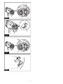
►Fig.15: 1. Limit mark
Check the carbon brushes regularly.
Replace them when they wear down to the limit mark.
Keep the carbon brushes clean and free to slip in the
holders. Both carbon brushes should be replaced at the
same time. Use only identical carbon brushes.
1. Use a screwdriver to remove two screws then
remove the rear cover.
►Fig.16: 1. Rear cover 2. Screw
2. Raise the arm part of the spring and then place
it in the recessed part of the housing with aslotted bit
screwdriver of slender shaft or the like.
►Fig.17: 1. Recessed part 2. Spring 3.Arm
3. Use pliers to remove the carbon brush caps of
the carbon brushes. Take out the worn carbon brushes,
insert the new ones and replace the carbon brush caps
in reverse.
►Fig.18: 1. Carbon brush cap
4. Make sure to place the lead wire in opposite side
of the arm.
►Fig.19: 1. Lead wire 2. Carbon brush cap
5. Make sure that the carbon brush caps have t into
the holes in brush holders securely.
►Fig.20: 1. Hole 2. Carbon brush cap
6. Reinstall the rear cover and tighten two screws
securely.
7. Insert the battery cartridge into the tool and break
in brushes by running tool with no load for about 1
minute.
8. Check the tool while running and electric brake
operation when releasing the switch trigger. If electric
brake is not working well, ask Makita Authorized or
Factory Service Centers for repair.
To maintain product SAFETY and RELIABILITY,
repairs, any other maintenance or adjustment should
be performed by Makita Authorized or Factory Service
Centers, always using Makita replacement parts.
OPTIONAL
ACCESSORIES
CAUTION: These accessories or attachments
are recommended for use with your Makita tool
specied in this manual. The use of any other
accessories or attachments might present a risk of
injury to persons. Only use accessory or attachment
for its stated purpose.
If you need any assistance for more details regard-
ing these accessories, ask your local Makita Service
Center.
• Drill bits
• Driver bits
• Tungsten-carbide tipped drill bit
• Blow-out bulb
• Driver bit holder
•Hook
• Makita genuine battery and charger
NOTE: Some items in the list may be included in the
tool package as standard accessories. They may
differ from country to country.

11 POLSKI
POLSKI (Instrukcja oryginalna)
DANE TECHNICZNE
Model: DHP482
Zakresy wiercenia Beton 13 mm
Stal 13 mm
Drewno 38 mm
Zakresy dokręcania Wkręt do drewna 10 mm x 90 mm
Wkręt maszynowy M6
Prędkość bez obciążenia Wysoka (2) 0–1 900 min-1
Niska (1) 0–600 min-1
Liczba udarów na minutę Wysoka (2) 0–28 500 min-1
Niska (1) 0–9 000 min-1
Długość całkowita 198 mm
Napięcie znamionowe Prąd stały 18 V
Akumulator BL1815N, BL1820, BL1820B BL1830, BL1840, BL1850, BL1830B,
BL1840B, BL1850B, BL1860B
Ciężar netto 1,5 kg 1,8 kg
• W związku ze stale prowadzonym przez naszą rmę programem badawczo-rozwojowym niniejsze dane mogą
ulec zmianom bez wcześniejszego powiadomienia.
• W innych krajach urządzenie może mieć odmienne parametry techniczne imoże być wyposażone winny
akumulator.
• Masa urządzenia wraz zakumulatorem obliczona zgodnie zprocedurą EPTA 01/2003
Przeznaczenie
Narzędzie jest przeznaczone do wiercenia udarowego
wcegle, betonie ikamieniu. Nadaje się też do wkrę-
cania wkrętów oraz wiercenia bez udaru wdrewnie,
metalu, materiałach ceramicznych itworzywach
sztucznych.
Hałas
Typowy równoważny poziom dźwięku Aokreślony w
oparciu onormę EN60745:
Poziom ciśnienia akustycznego (LpA): 82 dB(A)
Poziom mocy akustycznej (LWA): 93 dB (A)
Niepewność (K): 3dB(A)
OSTRZEŻENIE: Nosić ochronniki słuchu.
Drgania
Całkowita wartość poziomu drgań (suma wektorów w 3
osiach) określona zgodnie znormą EN60745:
Tryb pracy: wiercenie udarowe wbetonie
Emisja drgań (ah,ID): 6,0 m/s2
Niepewność (K): 1,5 m/s2
Tryb pracy: wiercenie wmetalu
Emisja drgań (ah,D): 2,5 m/s2lub mniej
Niepewność (K): 1,5 m/s2
WSKAZÓWKA: Deklarowana wartość wytwarzanych
drgań została zmierzona zgodnie ze standardową
metodą testową imożna ją wykorzystać do porówny-
wania narzędzi.
WSKAZÓWKA: Deklarowaną wartość wytwarzanych
drgań można także wykorzystać we wstępnej ocenie
narażenia.
OSTRZEŻENIE: Drgania wytwarzane podczas
rzeczywistego użytkowania elektronarzędzia mogą
się różnić od wartości deklarowanej, wzależności od
sposobu jego użytkowania.
OSTRZEŻENIE: W oparciu o szacowane
narażenie wrzeczywistych warunkach użytkowania
należy określić środki bezpieczeństwa wcelu ochrony
operatora (uwzględniając wszystkie elementy cyklu
działania, tj. czas, kiedy narzędzie jest wyłączone i
kiedy pracuje na biegu jałowym, atakże czas, kiedy
jest włączone).
Deklaracja zgodności WE
Dotyczy tylko krajów europejskich
Firma Makita oświadcza, że poniższe urządzenie(-a):
Oznaczenie maszyny: Akum. wiertarko-wkrętarka
udarowa
Model nr/typ: DHP482
Jest zgodne zwymogami określonymi wnastępujących
dyrektywach europejskich: 2006/42/EC
Jest/są produkowane zgodnie znastępującymi nor-
mami lub dokumentami normalizacyjnymi: EN60745
Dokumentacja techniczna zgodna wwymaganiami
dyrektywy 2006/42/EC jest dostępna w:
Makita, Jan-Baptist Vinkstraat 2, 3070, Belgia

12 POLSKI
30.3.2015
Yasushi Fukaya
Dyrektor
Makita, Jan-Baptist Vinkstraat 2, 3070, Belgia
Ogólne zasady bezpiecznej
eksploatacji elektronarzędzi
OSTRZEŻENIE: Przeczytać wszystkie ostrze-
żenia bezpieczeństwa i wszystkie instrukcje.
Niezastosowanie się do wspomnianych ostrzeżeń i
instrukcji może doprowadzić do porażenia prądem
elektrycznym, pożaru i/lub poważnych obrażeń ciała.
Wszystkie ostrzeżenia i instruk-
cje należy zachować do wykorzy-
stania w przyszłości.
Pojęcie „elektronarzędzie", występujące wwymienio-
nych tu ostrzeżeniach, odnosi się do elektronarzędzia
zasilanego zsieci elektrycznej (z przewodem zasilają-
cym) lub do elektronarzędzia akumulatorowego (bez
przewodu zasilającego).
Ostrzeżenia dotyczące
bezpieczeństwa dla akumulatorowej
wiertarko-wkrętarki udarowej
1. Podczas wiercenia udarowego należy nosić
ochronniki słuchu. Hałas może spowodować
utratę słuchu.
2. Używać narzędzia z uchwytami pomocniczymi,
jeśli zostały dostarczone wraz z nim. Utrata
kontroli może spowodować obrażenia ciała.
3. Trzymać elektronarzędzie za izolowane
powierzchnie rękojeści podczas wykonywania
prac, przy których wiertło może dotknąć niewi-
docznej instalacji elektrycznej. Zetknięcie wier-
tła zprzewodem elektrycznym znajdującym się
pod napięciem może spowodować, że odsłonięte
elementy metalowe elektronarzędzia również
znajdą się pod napięciem, grożąc porażeniem
operatora prądem elektrycznym.
4. Trzymać elektronarzędzie za izolowane
powierzchnie rękojeści podczas wykonywania
prac, przy których wkręcany wkręt lub śruba
mogą dotknąć niewidocznej instalacji elek-
trycznej. Zetknięcie wkrętu lub śruby zprzewo-
dem elektrycznym znajdującym się pod napięciem
spowoduje, że odsłonięte elementy metalowe
narzędzia również znajdą się pod napięciem, gro-
żąc porażeniem operatora prądem elektrycznym.
5.
Podczas pracy należy zadbać o dobre oparcie dla
nóg. W przypadku pracy na pewnej wysokości upew-
nić się, że na dole nie przebywają żadne osoby.
6. Narzędzie należy trzymać mocno i pewnie.
7. Trzymać ręce z dala od części obrotowych.
8. Nie pozostawiać włączonego narzędzia.
Narzędzie można uruchomić tylko, gdy jest
trzymane w rękach.
9. Nie dotykać wiertła ani części obrabianej od
razu po zakończeniu danej operacji; mogą one
być bardzo gorące i spowodować oparzenie
skóry.
10. Niektóre materiały zawierają substancje
chemiczne, które mogą być toksyczne.
Unikać wdychania pyłu i kontaktu ze skórą.
Przestrzegać przepisów bezpieczeństwa poda-
nych przez dostawcę materiałów.
ZACHOWAĆ NINIEJSZE
INSTRUKCJE.
OSTRZEŻENIE: NIE WOLNO pozwolić,
aby wygoda lub rutyna (nabyta w wyniku wielo-
krotnego używania urządzenia) zastąpiły ścisłe
przestrzeganie zasad bezpieczeństwa obsługi.
NIEWŁAŚCIWE UŻYTKOWANIE narzędzia lub
niestosowanie się do zasad bezpieczeństwa
podanych w niniejszej instrukcji obsługi może
prowadzić do poważnych obrażeń ciała.
Ważne zasady bezpieczeństwa
dotyczące akumulatora
1. Przed użyciem akumulatora zapoznać się ze
wszystkimi instrukcjami i znakami ostrze-
gawczymi na (1) ładowarce, (2) akumulatorze
i (3) produkcie, w którym będzie używany
akumulator.
2. Akumulatora nie wolno rozbierać.
3. Jeśli czas działania uległ znacznemu skróce-
niu, należy natychmiast przerwać pracę. Może
bowiem dojść do przegrzania, ewentualnych
poparzeń, a nawet eksplozji.
4. W przypadku przedostania się elektrolitu do
oczu, przemyć je czystą wodą i niezwłocznie
uzyskać pomoc lekarską. Może on bowiem
spowodować utratę wzroku.
5. Nie doprowadzać do zwarcia akumulatora:
(1) Nie dotykać styków materiałami przewo-
dzącymi prąd.
(2) Unikać przechowywania akumulatora w
pojemniku z metalowymi przedmiotami,
takimi jak gwoździe, monety itp.
(3) Chronić akumulator przed deszczem lub
wodą.
Zwarcie prowadzi do przepływu prądu elek-
trycznego o dużym natężeniu i przegrzania
akumulatora, co w konsekwencji może grozić
poparzeniami a nawet awarią urządzenia.
6. Narzędzia i akumulatora nie wolno przecho-
wywać w miejscach, w których temperatura
osiąga bądź przekracza 50°C (122°F).
7. Akumulatorów nie wolno spalać, również tych
poważnie uszkodzonych lub całkowicie zuży-
tych. Akumulator może eksplodować w ogniu.
8. Chronić akumulator przed upadkiem i
uderzeniami.
9. Nie wolno używać uszkodzonego akumulatora.
10. Stanowiące wyposażenie akumulatory lito-
wo-jonowe podlegają przepisom dotyczącym
produktów niebezpiecznych.
Na potrzeby transportu komercyjnego, np.

13 POLSKI
świadczonego przez rmy trzecie czy spedycyjne,
należy przestrzegać specjalnych wymagań w
zakresie pakowania i oznaczania etykietami.
Przygotowanie produktu do wysyłki wymaga
skonsultowania się ze specjalistą ds. materiałów
niebezpiecznych. Należy także przestrzegać
przepisów krajowych, które mogą być bardziej
szczegółowe.
Zakleić taśmą lub zaślepić otwarte styki akumula-
tora oraz zabezpieczyć go, aby nie mógł się prze-
suwać wopakowaniu.
11. Postępować zgodnie z przepisami lokalnymi
dotyczącymi usuwania akumulatorów.
ZACHOWAĆ NINIEJSZE
INSTRUKCJE.
PRZESTROGA: Używać wyłącznie oryginal-
nych akumulatorów rmy Makita. Używanie nie-
oryginalnych akumulatorów rm innych niż Makita lub
akumulatorów, które zostały zmodykowane, może
spowodować wybuch akumulatora ipożar, obrażenia
ciała oraz zniszczenie mienia. Stanowi to również
naruszenie warunków gwarancji rmy Makita doty-
czących narzędzia iładowarki.
Wskazówki dotyczące zacho-
wania maksymalnej trwałości
akumulatora
1. Akumulator należy naładować zanim zostanie
do końca rozładowany. Po zauważeniu spadek
mocy narzędzia należy przerwać pracę i nała-
dować akumulator.
2. Nie wolno ładować powtórnie w pełni nałado-
wanego akumulatora. Przeładowanie akumula-
tora skraca jego trwałość.
3. Akumulator należy ładować w temperaturze
pokojowej w przedziale 10–40°C (50–104°F). W
przypadku gorącego akumulatora przed przy-
stąpieniem do ładowania należy poczekać, aż
ostygnie.
4. Akumulatory niklowo-wodorkowe należy nała-
dować po okresie długiego nieużytkowania
(dłuższego niż sześć miesięcy).
OPIS DZIAŁANIA
PRZESTROGA: Przed przystąpieniem do regu-
lacji lub przeglądu narzędzia upewnić się, że jest
ono wyłączone, a akumulator został wyjęty.
Wkładanie i wyjmowanie
akumulatora
PRZESTROGA: Przed włożeniem lub wyjęciem
akumulatora należy zawsze wyłączyć narzędzie.
PRZESTROGA: Podczas wkładania lub wyjmo-
wania akumulatora należy mocno trzymać narzę-
dzie i akumulator. Wprzeciwnym razie mogą się one
wyślizgnąć zrąk, powodując uszkodzenie narzędzia
lub akumulatora iobrażenia ciała.
►Rys.1: 1. Czerwony wskaźnik 2. Przycisk
3. Akumulator
Aby wyjąć akumulator, przesuń przycisk znajdujący się
wprzedniej jego części iwysuń akumulator.
Aby włożyć akumulator, wyrównaj występ na akumulato-
rze zrowkiem wobudowie iwsuń go na swoje miejsce.
Akumulator należy wsunąć do oporu, aż się zatrzaśnie na
miejscu, co jest sygnalizowane delikatnym kliknięciem.
Jeśli wgórnej części przycisku jest widoczny czerwony
wskaźnik, akumulator nie został całkowicie zatrzaśnięty.
PRZESTROGA: Akumulator należy włożyć
do końca, tak aby czerwony wskaźnik nie był
widoczny. Wprzeciwnym razie może przypadkowo
wypaść znarzędzia, powodując obrażenia operatora
lub osób postronnych.
PRZESTROGA: Nie wkładać akumulatora na
siłę. Jeśli akumulator nie daje się swobodnie wsunąć,
oznacza to, że został włożony nieprawidłowo.
Układ zabezpieczenia akumulatora
Akumulator litowo-jonowy oznaczony gwiazdką
►Rys.2: 1. Znak gwiazdki
Akumulatory litowo-jonowe ze znakiem gwiazdki są
wyposażone wukład zabezpieczający. Układ ten auto-
matycznie odcina zasilanie narzędzia wcelu wydłuże-
nia żywotności akumulatora.
Narzędzie zostanie automatycznie zatrzymane pod-
czas pracy wnastępujących sytuacjach związanych z
narzędziem/akumulatorem:
Przeciążenie:
Narzędzie pracuje wsposób, który powoduje pobór
nadmiernie wysokiego prądu.
Wtakiej sytuacji należy wyłączyć narzędzie izaprze-
stać wykonywania czynności powodującej przeciążenie
narzędzia. Następnie należy włączyć narzędzie wcelu
jego ponownego uruchomienia.
Jeśli narzędzie nie uruchomi się, oznacza to, że akumulator
jest przegrzany. Wtakiej sytuacji, przed ponownym urucho-
mieniem narzędzia należy odczekać, aż akumulator ostygnie.
Niskie napięcie akumulatora:
Poziom naładowania akumulatora jest zbyt niski, aby
narzędzie mogło pracować. Wtakiej sytuacji należy
wyjąć akumulator igo naładować.

14 POLSKI
Wskazanie stanu naładowania
akumulatora
Tylko akumulatory oznaczone literą „B” na końcu
model
►Rys.3: 1. Lampki wskaźnika 2. Przycisk kontrolny
Nacisnąć przycisk kontrolny na akumulatorze wcelu
wyświetlenia stanu naładowania akumulatora. Lampki
wskaźnika zaświecą się przez kilka sekund.
Lampki wskaźnika Pozostała
energia
akumulatora
Świeci się Wyłączony Miga
75–100%
50–75%
25–50%
0–25%
Naładować
akumulator.
Akumulator
może nie
działać
poprawnie.
WSKAZÓWKA: Zależnie od warunków użytkowania
itemperatury otoczenia, wskazywany poziom może
nieznacznie się różnić od rzeczywistego stanu nała-
dowania akumulatora.
Działanie przełącznika
►Rys.4: 1. Spust przełącznika
PRZESTROGA: Przed włożeniem akumulatora
do narzędzia należy zawsze sprawdzić, czy spust
przełącznika działa prawidłowo i czy powraca do
położenia wyłączenia po jego zwolnieniu.
Wcelu uruchomienia narzędzia wystarczy pociągnąć
spust przełącznika. Prędkość narzędzia zwiększa się
wraz ze zwiększaniem nacisku na spust przełącznika.
Wcelu zatrzymania urządzenia należy zwolnić spust
przełącznika.
Włączanie lampki czołowej
►Rys.5: 1. Lampka
PRZESTROGA: Nie patrzeć na światło ani
bezpośrednio na źródło światła.
Wcelu włączenia lampki należy pociągnąć za spust przełącz-
nika. Lampka świeci, dopóki spust przełącznika jest naciskany.
Lampka gaśnie po 10–15 sod zwolnienia spustu przełącznika.
WSKAZÓWKA:Aby usunąć zabrudzenia zklosza
lampki, należy użyć suchej szmatki. Uważać, aby nie
zarysować klosza lampki, gdyż może to zmniejszyć
natężenie oświetlenia.
Działanie przełącznika zmiany
kierunku obrotów
►Rys.6: 1. Dźwignia przełącznika zmiany kierunku
obrotów
PRZESTROGA: Przed przystąpieniem do pracy
należy zawsze sprawdzić ustawiony kierunek
obrotów.
PRZESTROGA: Przełącznika zmiany kie-
runku obrotów można użyć tylko po całkowitym
zatrzymaniu narzędzia. Zmiana kierunku obro-
tów przed zatrzymaniem się narzędzia grozi jego
uszkodzeniem.
PRZESTROGA: Gdy narzędzie nie jest uży-
wane, należy zawsze ustawić dźwignię prze-
łącznika zmiany kierunku obrotów w położeniu
neutralnym.
Omawiane narzędzie jest wyposażone wprzełącznik
umożliwiający zmianę kierunku obrotów. Wcelu uzy-
skania obrotów wprawą stronę należy wcisnąć dźwi-
gnię przełącznika zmiany kierunku obrotów po stronie
A, natomiast aby uzyskać obroty wlewą stronę, należy
wcisnąć dźwignię przełącznika po stronie B.
Gdy dźwignia przełącznika zmiany kierunku obrotów
znajduje się wpołożeniu neutralnym, spust przełącz-
nika jest zablokowany.
Zmiana prędkości
►Rys.7: 1. Dźwignia zmiany prędkości
PRZESTROGA: Dźwignię zmiany prędkości
należy zawsze ustawiać dokładnie w wybranej
pozycji. Wprzypadku uruchomienia narzędzia przy
dźwigni zmiany prędkości ustawionej wpołowie
między pozycją „1" i„2" może dojść do uszkodzenia
narzędzia.
PRZESTROGA: Nie wolno używać dźwi-
gni zmiany prędkości, gdy narzędzie pracuje.
Narzędzie może ulec uszkodzeniu.
Położenie
dźwigni
zmiany
prędkości
Prędkość Moment
obrotowy Odpowiedni
tryb pracy
1Niska Wysoka Praca przy
dużym
obciążeniu
2Wysoki Niski Praca przy
małym
obciążeniu
Wcelu zmiany prędkości należy najpierw wyłączyć
narzędzie. Wybrać położenie „2” wcelu ustawienia
wysokiej prędkości lub położenie „1” wcelu ustawienia
niskiej prędkości, ale dużego momentu. Przed rozpo-
częciem pracy należy sprawdzić, czy dźwignia zmiany
prędkości jest ustawiona we właściwym położeniu.
Jeśli prędkość narzędzia drastycznie spadnie podczas
pracy zdźwignią ustawioną wpołożeniu „2”, należy
przesunąć dźwignię do położenia „1” iponownie przy-
stąpić do pracy.

15 POLSKI
Wybór trybu pracy
PRZESTROGA:
Pierścień należy zawsze ustawić
dokładnie w pozycji symbolu odpowiadającego wybra-
nemu trybowi pracy. W przypadku uruchomienia narzę-
dzia, gdy pierścień jest ustawiony jest między symbo-
lami trybu pracy, może dojść do uszkodzenia narzędzia.
PRZESTROGA:
Mogą wystąpić pewne niewiel-
kie trudności z przestawieniem pierścienia zmiany
trybu pracy z pozycji „ ” do innego trybu pracy.
W takiej sytuacji należy włączyć narzędzie na
sekundę w pozycji „ ”, a następnie wyłączyć je
i przesunąć pierścień do wybranej pozycji.
►Rys.8: 1. Pierścień zmiany trybu pracy 2. Pierścień
regulacyjny 3. Podziałka 4. Strzałka
Narzędzie ma trzy tryby pracy.
•–tryb wiercenia (tylko ruch obrotowy)
•–tryb wiercenia udarowego (ruch obrotowy z
udarem)
•–tryb wkręcania (ruch obrotowy ze
sprzęgłem)
Wybrać jeden ztrybów odpowiadający danej pracy.
Obrócić pierścień zmiany trybu pracy iwyrównać
wybrany symbol trybu ze strzałką znajdującą się na
korpusie narzędzia.
Regulacja momentu dokręcenia
►Rys.9: 1. Pierścień zmiany trybu pracy 2. Pierścień
regulacyjny 3. Podziałka 4. Strzałka
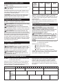
Moment dokręcenia można regulować w21 stopniach,
obracając pierścień regulacyjny. Wyrównać podziałkę
ze strzałką znajdującą się na korpusie narzędzia.
Położenie 1odnosi się do minimalnego momentu
dokręcenia, asymbol 21 do maksymalnego momentu
dokręcenia.
Przed przystąpieniem do pracy należy przeprowadzić
próbę wkręcania wdany element lub inny element z
tego samego materiału, aby ustalić poziom momentu
dokręcenia wymagany wdanym zastosowaniu.
Poniższa tabela przedstawia ogólną zależność pomię-
dzy rozmiarem wkrętu apodziałką.
Podziałka 12345678910 11 12 13 14 15 16 17 18 19 20 21
Wkręt maszynowy M4 M5 M6
Wkręt do
drewna Miękkie
drewno
(np. sosna)
–ɸ3,5 x 22 ɸ4,1 x 38 –
Twarde
drewno
(np.
mahoń)
–ɸ3,5 x 22 ɸ4,1 x 38 –
MONTAŻ
PRZESTROGA: Przed przystąpieniem do prac
konserwacyjnych przy narzędziu upewnić się,
że jest ono wyłączone, a akumulator został wyjęty.
Wkładanie i wyjmowanie końcówki
wkrętakowej/wiertła
Akcesoria opcjonalne
►Rys.10: 1. Tuleja 2. Zamykanie 3. Otwieranie
Aby otworzyć szczęki uchwytu, obrócić tuleję wlewą
stronę. Umieścić jak najgłębiej końcówkę wkrętakową/
wiertło wuchwycie. Obrócić tuleję wprawą stronę, aby
zacisnąć uchwyt. Wcelu wyjęcia końcówki wkrętako-
wej/wiertła obrócić tuleję wlewą stronę.
Zamontowanie zaczepu
►Rys.11: 1. Rowek 2. Zaczep 3. Wkręt
Zaczep służy do wygodnego, tymczasowego zawieszania
narzędzia. Można go zamontować zjednej lub zdrugiej
strony narzędzia. Aby zamontować zaczep, należy wsunąć
go wrowek wobudowie narzędzia znajdujący się zobu
stron, anastępnie przykręcić go wkrętem. Aby wymonto-
wać zaczep, należy odkręcić wkręt iwyjąć zaczep.
Zamontowywanie uchwytu
końcówki wkrętakowe
Akcesoria opcjonalne
►Rys.12: 1. Uchwyt na końcówki wkrętakowe
2. Końcówka wkrętakowa
Włożyć uchwyt na końcówki wkrętakowe do występu w
stopie narzędzia zprawej bądź zlewej strony iprzymo-
cować go wkrętem.
Nieużywane końcówki wkrętakowe należy trzymać
wuchwycie. Wuchwycie można trzymać końcówki o
długości 45 mm.

16 POLSKI
OBSŁUGA
PRZESTROGA: Akumulator należy wsunąć
do oporu, aż wskoczy na swoje miejsce. Jeśli jest
widoczny czerwony wskaźnik wgórnej części przy-
cisku, akumulator nie został całkowicie zatrzaśnięty.
Należy go wsunąć do oporu, aż czerwony wskaźnik
przestanie być widoczny. Wprzeciwnym razie może
on przypadkowo wypaść znarzędzia, powodując
obrażenia operatora lub osób postronnych.
PRZESTROGA: W przypadku drastycznego
spadku prędkości należy zredukować obciążenie
lub wyłączyć narzędzie, aby nie dopuścić do jego
uszkodzenia.
Narzędzie należy trzymać jedną ręką za uchwyt, a
drugą za spód akumulatora, aby kontrolować jego
przekręcanie.
►Rys.13
Wkręcanie
PRZESTROGA: Ustawić pierścień regulacyjny
w pozycji odpowiadającej właściwemu dla danej
operacji momentowi dokręcenia.
PRZESTROGA: Końcówka wkrętakowa
powinna być wprowadzona do łba wkrętu w linii
prostej z wkrętem, w przeciwnym razie wkręt i/lub
końcówka mogą ulec uszkodzeniu.
Najpierw należy obrócić pierścień zmiany trybu pracy
wtakie położenie, aby strzałka na korpusie narzędzia
wskazywała symbol .
Wsunąć czubek końcówki wkrętakowej do gniazda we
łbie wkrętu idocisnąć narzędzie. Uruchomić narzędzie
powoli, anastępnie stopniowo zwiększać prędkość.
Zwolnić spust przełącznika, gdy tylko zadziała sprzęgło.
WSKAZÓWKA: Wprzypadku wkręcania wkrętu do
drewna należy wstępnie nawiercić otwór prowadzący
ośrednicy 2/3 średnicy wkrętu. Ułatwi to wkręcanie i
zapobiegnie rozłupywaniu się elementu obrabianego.
Wiercenie udarowe
PRZESTROGA: W momencie przewiercania
otworu na wylot, gdy otwór jest zapchany wiórami
lub opiłkami bądź w przypadku uderzenia w pręty
zbrojeniowe znajdujące się w betonie, na narzę-
dzie/wiertło jest wywierana nagle olbrzymia siła
skręcająca.
Najpierw należy obrócić pierścień zmiany trybu pracy
wtakie położenie, aby strzałka na korpusie narzędzia
wskazywała symbol .Za pomocą pierścienia regu-
lacyjnego można ustawić dowolną wartość momentu
wymaganego do wykonania danej operacji.
Należy koniecznie używać wiertła zkońcówką zwęglika
wolframu.
Ustawić wiertło wwybranym miejscu, gdzie ma być
wywiercony otwór, anastępnie pociągnąć za spust
przełącznika. Nie przeciążać narzędzia. Lekki nacisk
daje najlepsze wyniki. Trzymać narzędzie wustalonej
pozycji, uważając, aby wiertło nie wypadło zotworu.
Nie zwiększać nacisku, gdy otwór zapcha się wiórami,
opiłkami lub gruzem. Zamiast tego należy pozwolić,
aby narzędzie pracowało przez chwilę bez obciążenia,
anastępnie wyciągnąć wiertło częściowo zotworu. Po
kilkukrotnym powtórzeniu tej procedury otwór zostanie
oczyszczony ibędzie można wznowić wiercenie w
normalny sposób.
Gruszka do przedmuchiwania
Akcesoria opcjonalne
►Rys.14: 1. Gruszka do przedmuchiwania
Po wywierceniu otworu można użyć gruszki do
przedmuchiwania, aby oczyścić otwór zpyłu.
Wiercenie
Najpierw obrócić pierścień regulacyjny tak, aby strzałka
wskazywała symbol .Następnie postępować zgod-
nie zponiższym opisem.
Wiercenie w drewnie
Wprzypadku wiercenia wdrewnie najlepsze rezultaty
uzyskuje się, stosując wiertła zakończone wkrętem
prowadzącym. Wkręt prowadzący ułatwia wiercenie,
ponieważ wciąga wiertło welement obrabiany.
Wiercenie w metalu
Aby uniknąć ześlizgiwania się wiertła na początku
operacji, należy za pomocą punktaka imłotka wykonać
wgłębienie wmiejscu, wktórym ma być wykonany
otwór. Umieścić końcówkę wiertła we wgłębieniu iroz-
począć wiercenie.
Podczas wiercenia wmetalu należy stosować odpo-
wiednie chłodziwo. Wyjątki stanowią żelazo imosiądz,
które należy wiercić na sucho.
PRZESTROGA: Wywieranie nadmiernego
nacisku na narzędzie nie przyspiesza wiercenia.
W praktyce, wywieranie nadmiernego nacisku przy-
czynia się jedynie do uszkodzenia końcówki wiertła,
zmniejszenia wydajności iskrócenia okresu eksplo-
atacyjnego narzędzia.
PRZESTROGA: Gdy wiertło zaczyna przebijać
na wylot otwór w obrabianym elemencie, należy
zachować ostrożność i mocno trzymać narzędzie.
Wmomencie przebijania otworu na narzędzie/wiertło
wywierana jest olbrzymia siła.
PRZESTROGA: Zakleszczone wiertło można
łatwo wyjąć, zmieniając kierunek obrotów i wycią-
gając wiertło. Należy jednak pamiętać, że narzę-
dzie może się gwałtownie cofnąć, jeśli nie będzie
mocno trzymane.
PRZESTROGA: Niewielkie elementy obrabiane
należy zawsze zamocować w imadle lub podob-
nym przyrządzie.
PRZESTROGA: Jeżeli narzędzie jest używane
bez przerwy aż do rozładowania akumulatora,
należy je odstawić na 15 minut przed podjęciem
pracy na nowo z użyciem innego naładowanego
akumulatora.

17 POLSKI
KONSERWACJA
PRZESTROGA: Przed przystąpieniem do prze-
glądu narzędzia lub jego konserwacji upewnić się,
że jest ono wyłączone, a akumulator wyjęty.
UWAGA: Nie stosować benzyny, rozpuszczalni-
ków, alkoholu itp. środków. Mogą one powodo-
wać odbarwienia, odkształcenia lub pęknięcia.
Wymiana szczotek węglowych
►Rys.15: 1. Oznaczenie limitu
Systematycznie sprawdzać szczotki węglowe.
Wymieniać je, gdy ich zużycie sięga oznaczenia limitu.
Szczotki węglowe powinny być czyste, aby można je
było swobodnie wsunąć do opraw. Należy wymieniać
obydwie szczotki jednocześnie. Stosować wyłącznie
identyczne szczotki węglowe.
1. Za pomocą śrubokręta wykręć dwa wkręty, a
następnie zdejmij tylną osłonę.
►Rys.16: 1. Tylna osłona 2. Wkręt
2. Za pomocą cienkiego śrubokręta płaskiego lub
podobnego narzędzia podnieś ramię sprężyny, a
następnie wsuń je wgniazdo wobudowie.
►Rys.17: 1. Gniazdo 2. Sprężyna 3. Ramię
3. Za pomocą szczypiec wyjmij nasadki szczotek
węglowych. Wyjmij zużyte szczotki węglowe, włóż nowe
izpowrotem załóż nasadki szczotek, wykonując czyn-
ności wodwrotnej kolejności.
►Rys.18: 1. Nasadka szczotki węglowej
4. Upewnij się, że przewód biegnie po przeciwnej
stronie ramienia.
►Rys.19: 1. Przewód 2. Nasadka szczotki węglowej
5. Upewnij się, że nasadki szczotek węglowych
dobrze tkwią wotworach uchwytów szczotek.
►Rys.20: 1. Otwór 2. Nasadka szczotki węglowej
6. Załóż zpowrotem tylną osłonę, anastępnie
dobrze dokręć oba wkręty.
7. Po zakończeniu wymiany szczotek włóż akumula-
tor do narzędzia iwłącz je na około 1min bez obciąże-
nia, aby dotrzeć szczotki.
8. Następnie sprawdź działanie narzędzia podczas
pracy. Sprawdź także skuteczność hamulca elektrycz-
nego po zwolnieniu spustu przełącznika. Jeśli hamulec
elektryczny nie działa prawidłowo, zleć naprawę urzą-
dzenia autoryzowanemu lub fabrycznemu punktowi
serwisowemu narzędzi Makita.
W celu zachowania odpowiedniego poziomu
BEZPIECZEŃSTWA iNIEZAWODNOŚCI produktu
wszelkie naprawy iróżnego rodzaju prace konserwa-
cyjne lub regulacje powinny być przeprowadzane przez
autoryzowany lub fabryczny punkt serwisowy narzędzi
Makita, zawsze zużyciem oryginalnych części zamien-
nych Makita.
AKCESORIA
OPCJONALNE
PRZESTROGA: Zaleca się stosowanie wymie-
nionych akcesoriów i przystawek razem z narzę-
dziem Makita opisanym w niniejszej instrukcji.
Stosowanie innych akcesoriów lub przystawek
może być przyczyną obrażeń ciała. Akcesoria lub
przystawki należy wykorzystywać tylko zgodnie zich
przeznaczeniem.
Wrazie potrzeby wszelkiej pomocy iszczegółowych
informacji na temat niniejszych akcesoriów udzielą
Państwu lokalne punkty serwisowe Makita.
• Wiertła
• Końcówki wkrętakowe
• Wiertło zkońcówką zwęglika wolframu
•Gruszka do przedmuchiwania
• Uchwyt na końcówki wkrętakowe
•Zaczep
• Oryginalny akumulator iładowarka rmy Makita
WSKAZÓWKA: Niektóre pozycje znajdujące się na
liście mogą być dołączone do pakietu narzędziowego
jako akcesoria standardowe. Mogą to być różne
pozycje, wzależności od kraju.

18 MAGYAR
MAGYAR (Eredeti utasítások)
RÉSZLETES LEÍRÁS
Típus: DHP482
Fúrási teljesítmény Beton 13 mm
Acél 13 mm
Fa 38 mm
Meghúzási teljesítmény Facsavar 10 mm x 90 mm
Gépcsavar M6
Üresjárati fordulatszám Magas (2) 0 - 1 900 min-1
Alacsony (1) 0 - 600 min-1
Lökésszám percenként Magas (2) 0 - 28 500 min-1
Alacsony (1) 0 - 9 000 min-1
Teljes hossz 198 mm
Névleges feszültség 18 V, egyenáram
Akkumulátor BL1815N, BL1820, BL1820B BL1830, BL1840, BL1850, BL1830B,
BL1840B, BL1850B, BL1860B
Tiszta tömeg 1,5 kg 1,8 kg
• Folyamatos kutató- és fejlesztőprogramunk eredményeként az itt felsorolt tulajdonságok gyelmeztetés nélkül
megváltozhatnak.
• A műszaki adatok és az akkumulátor országonként változhatnak.
• Súly az akkumulátorral, a01/2003 EPTA eljárás szerint meghatározva
Rendeltetés
Aszerszám tégla, beton és kő ütvefúrására használ-
ható. Alkalmas csavarbehajtásra és ütés nélküli fúrásra
is fába, fémekbe, kerámiába és műanyagokba.
Zaj
Atipikus A-súlyozású zajszint, aEN60745 szerint
meghatározva:
Hangnyomásszint (LpA): 82 dB(A)
Hangteljesítményszint (LWA): 93 dB (A)
Bizonytalanság (K): 3dB(A)
FIGYELMEZTETÉS: Viseljen fülvédőt!
Vibráció
Avibráció teljes értéke (háromtengelyű vektorösszeg)
az EN60745 szerint meghatározva:
Üzemmód: ütvefúrás betonba
Rezgéskibocsátás (ah,ID): 6,0 m/s2
Bizonytalanság (K): 1,5 m/s2
Üzemmód: fúrás fémbe
Rezgéskibocsátás (ah,D): 2,5 m/s2vagy kisebb
Bizonytalanság (K): 1,5 m/s2
MEGJEGYZÉS: Arezgéskibocsátás értéke aszabvá-
nyos vizsgálati eljárásnak megfelelően lett mérve, és
segítségével az elektromos kéziszerszámok össze-
hasonlíthatók egymással.
MEGJEGYZÉS: Arezgéskibocsátás értékének segít-
ségével előzetesen megbecsülhető arezgésnek való
kitettség mértéke.
FIGYELMEZTETÉS:Aszerszám rezgéskibo-
csátása egy adott alkalmazásnál eltérhet amegadott
értéktől ahasználat módjától függően.
FIGYELMEZTETÉS: Határozza meg akezelő
védelmét szolgáló munkavédelmi lépéseket, melyek
az adott munkafeltételek melletti vibrációs hatás
becsült mértékén alapulnak (gyelembe véve a
munkaciklus elemeit, mint például agép leállításának
és üresjáratának mennyiségét az elindítások száma
mellett).
EK Megfelelőségi nyilatkozat
Csak európai országokra vonatkozóan
AMakita kijelenti, hogy az alábbi gép(ek):
Gép megnevezése: Akkumulátoros csavarbehajtó
Típus sz./Típus: DHP482
Megfelel akövetkező Európai irányelveknek:
2006/42/EC
Gyártása akövetkező szabványoknak, valamint szab-
ványosított dokumentumoknak megfelelően történik:
EN60745
Aműszaki leírás a2006/42/EC előírásainak megfele-
lően elérhető innen:
Makita, Jan-Baptist Vinkstraat 2, 3070, Belgium
30.3.2015
Yasushi Fukaya
Igazgató
Makita, Jan-Baptist Vinkstraat 2, 3070, Belgium

19 MAGYAR
A szerszámgépekre vonatkozó
általános biztonsági
gyelmeztetések
FIGYELMEZTETÉS: Olvassa el az összes
biztonsági gyelmeztetést és utasítást. Ha nem
tartja be agyelmeztetéseket és utasításokat, akkor
áramütés, tűz és/vagy súlyos sérülés következhet be.
Őrizzen meg minden gyelmez-
tetést és utasítást a későbbi tájé-
kozódás érdekében.
Agyelmeztetésekben szereplő "szerszámgép" kife-
jezés az Ön hálózatról (vezetékes) vagy akkumulá-
torról (vezeték nélküli) működtetett szerszámgépére
vonatkozik.
Biztonsági gyelmeztetések
akkumulátoros csavarbehajtóhoz
1. Ütvefúráskor viseljen fülvédőt. Azajterhelés
halláskárosodást okozhat.
2. Használja a szerszámhoz mellékelt kisegítő
fogantyúkat. Az irányítás elvesztése személyi
sérülést okozhat.
3. A szerszámgépet a szigetelt markolófelülete-
inél fogja, ha olyan műveletet végez, amikor
a vágóeszköz rejtett vezetékkel érintkezhet.
Áram alatt lévő vezetékekkel való érintkezéskor a
szerszám fém alkatrészei is áram alá kerülhetnek,
és megrázhatják akezelőt.
4. Tartsa az elektromos szerszámot a szige-
telt markolófelületeinél fogva amikor olyan
műveletet végez, amelyben fennáll a veszélye,
hogy a rögzítő rejtett vezetékekbe ütközhet. A
rögzítők áram alatt lévő vezetékekkel való érint-
kezésekor aszerszám fém alkatrészei is áram alá
kerülnek, és megrázhatják akezelőt.
5. Mindig stabil helyzetben dolgozzon. A szer-
szám magasban történő használatkor győződ-
jön meg arról, hogy nem tartózkodik-e valaki
odalent.
6. Biztosan tartsa a szerszámot.
7. Ne nyúljon a forgó részekhez.
8. Ne hagyja a működő szerszámot felügye-
let nélkül. Csak kézben tartva használja a
szerszámot.
9. Ne érjen a szerszámhoz vagy a munkadarab-
hoz közvetlenül a munkavégzést követően;
azok rendkívül forrók lehetnek és megégethe-
tik a bőrét.
10. Egyes anyagok mérgező vegyületet tartal-
mazhatnak. Gondoskodjon a por belélegzése
elleni és érintés elleni védelemről. Tartsa be az
anyag szállítójának biztonsági utasításait.
ŐRIZZE MEG EZEKET AZ
UTASÍTÁSOKAT.
FIGYELMEZTETÉS: NE HAGYJA, hogy (a
termék többszöri használatából eredő) kényelem
és megszokás váltsa fel a termék biztonsági
előírásainak szigorú betartását. A HELYTELEN
HASZNÁLAT és a használati útmutatóban sze-
replő biztonsági előírások megszegése súlyos
személyi sérülésekhez vezethet.
Fontos biztonsági utasítások az
akkumulátorra vonatkozóan
1. Az akkumulátor használata előtt tanulmá-
nyozza át az akkumulátortöltőn (1), az akkumu-
látoron (2) és az akkumulátorral működtetett
terméken (3) olvasható összes utasítást és
gyelmeztető jelzést.
2. Ne szerelje szét az akkumulátort.
3.
Ha a működési idő nagyon lerövidült, azonnal hagyja
abba a használatot. Ez a túlmelegedés, esetleges
égések és akár robbanás veszélyével is járhat.
4. Ha elektrolit kerül a szemébe, mossa ki azt
tiszta vízzel és azonnal kérjen orvosi segítsé-
get. Ez a látásának elvesztését okozhatja.
5. Ne zárja rövidre az akkumulátort:
(1) Ne érjen az érintkezőkhöz elektromosan
vezető anyagokkal.
(2) Ne tárolja az akkumulátort más fémtár-
gyakkal, mint pl. szegekkel, érmékkel,
stb. egy helyen.
(3) Ne tegye ki az akkumulátort víznek vagy
esőnek.
Az akkumulátor rövidzárlata nagy áramerőssé-
get, túlmelegedést, égéseket, sőt akár meghi-
básodást is okozhat.
6. Ne tárolja a szerszámot vagy az akkumulátort
olyan helyen, ahol a hőmérséklet elérheti vagy
meghaladhatja az 50 °C-ot (122 °F).
7. Ne égesse el az akkumulátort még akkor
sem, ha az komolyan megsérült vagy teljesen
elhasználódott. Az akkumulátor a tűzben
felrobbanhat.
8. Vigyázzon, nehogy leejtse vagy megüsse az
akkumulátort.
9. Ne használjon sérült akkumulátort.
10. A készülékben található lítium-ion akkumuláto-
rokra a veszélyes árukkal kapcsolatos előírá-
sok vonatkoznak.
Atermék pl. harmadik felek, fuvarozó cégek stb.
által történő szállítása esetén minden esetben
tartsa szem előtt acsomagoláson és acímkén
található speciális követelményeket.
Atermék szállításra történő felkészítése esetén
vegye fel akapcsolatot egy veszélyes anyagokkal
foglalkozó szakemberrel. Kérjük, hogy az eset-
legesen szigorúbb nemzeti előírásokat is vegye
gyelembe.
Ragassza le akiálló érintkezőket, illetve oly
módon csomagolja be az akkumulátort, hogy az
ne tudjon elmozdulni acsomagolásban.
11. Az akkumulátor ártalmatlanításakor tartsa be a
helyi előírásokat.

20 MAGYAR
ŐRIZZE MEG EZEKET AZ
UTASÍTÁSOKAT.
VIGYÁZAT: Csak eredeti Makita akkumuláto-
rokat használjon.Anem eredeti Makita akkumu-
látorok vagy módosított akkumulátorok használata
esetén az akkumulátor felrobbanhat, ami tüzet,
személyi sérülést és anyagi kárt okozhat. AMakita
szerszámra és töltőre vonatkozó Makita garanciát is
érvénytelenítheti.
Tippek az akkumulátor maximá-
lis élettartamának eléréséhez
1. Töltse fel az akkumulátort, mielőtt teljesen
lemerülne. Állítsa le a gépet, és töltse fel az
akkumulátort, ha a gép erejének csökkenését
észleli.
2. Soha ne töltse újra a teljesen feltöltött akku-
mulátort. A túltöltés csökkenti az akkumulátor
élettartamát.
3. Töltse az akkumulátort szobahőmérsékleten,
10 °C - 40 °C (50 °F - 104 °F) között. Töltés előtt
hagyja lehűlni a fölforrósodott akkumulátort.
4. Töltse fel az akkumulátort, ha hosszabb ideje
(több mint hat hónapja) nem használta azt.
A MŰKÖDÉS LEÍRÁSA
VIGYÁZAT: Minden esetben ellenőrizze, hogy
a szerszám ki van kapcsolva és az akkumulátor
eltávolításra került mielőtt beállít vagy ellenőriz
valamilyen funkciót a szerszámon.
Az akkumulátor behelyezése és
eltávolítása
VIGYÁZAT: Mindig kapcsolja ki az eszközt,
mielőtt behelyezi vagy eltávolítja az akkumulátort.
VIGYÁZAT: Az akkumulátor behelyezésekor
vagy eltávolításakor erősen fogja meg a szerszá-
mot és az akkumulátort. Ha nem fogja erősen a
szerszámot és az akkumulátort, azok kicsúszhatnak a
kezei közül, ami aszerszám és az akkumulátor káro-
sodásához, de akár személyi sérüléshez is vezethet.
►Ábra1: 1. Piros jel 2. Gomb 3. Akkumulátor
Az akkumulátoregység kivételéhez nyomja be az akku-
mulátoregység elején található gombot, és húzza le a
gépről.
Az akkumulátor beszereléséhez illessze az akkumulá-
tor nyelvét aburkolaton található vájatba és csúsztassa
ahelyére. Egészen addig tolja be, amíg az akkumulátor
egy kis kattanással ahelyére nem ugrik. Ha látható a
piros jel agomb felső oldalán, akkor agomb nem kat-
tant be teljesen.
VIGYÁZAT: Mindig tolja be teljesen az akku-
mulátort, amíg a piros jel el nem tűnik. Ha ez nem
történik meg, akkor az akkumulátor kieshet aszer-
számból, és Önnek vagy akörnyezetében másnak
sérülést okozhat.
VIGYÁZAT: Ne erőltesse az akkumulátort behe-
lyezéskor. Ha az akkumulátor nem csúszik be köny-
nyedén, akkor nem megfelelően lett behelyezve.
Akkumulátorvédő rendszer
Csillag jelzéssel ellátott lítiumion akkumulátorok
►Ábra2: 1. Csillag jelzés
Acsillag jelzéssel ellátott lítiumion akkumulátorokat
akkumulátorvédő rendszerrel szerelik fel. Ez arendszer
automatikusan kikapcsolja aszerszám áramellátását,
így megnöveli az akkumulátor élettartamát.
Aszerszám használat közben automatikusan leáll, ha
aszerszám és/vagy az akkumulátor akövetkező hely-
zetbe kerül:
Túlterhelt:
Aszerszámot úgy működteti, hogy áramfelvétele ren-
dellenesen magas.
Ilyenkor kapcsolja ki agépet, és állítsa le azt az alkal-
mazást, amelyik atúlterhelést okozza. Újraindításhoz
kapcsolja be agépet.
Ha a szerszám nem indul el, az akkumulátor túlmele-
gedett. Ilyenkor hagyja kihűlni az akkumulátort, mielőtt
ismét bekapcsolná agépet.
Az akkumulátor feszültsége alacsony:
Az akkumulátor fennmaradó kapacitása túl alacsony, a
szerszámot nem tudja működtetni. Ilyenkor vegye le és
töltse fel az akkumulátort.
Az akkumulátor töltöttségének
jelzése
Csak olyan akkumulátorokhoz, amelyeknek a típus-
jelzésében „B” az utolsó betű
►Ábra3: 1. Jelzőlámpák 2. Check (ellenőrzés) gomb
Nyomja meg az ellenőrzőgombot, hogy az akkumulá-
tortöltöttség-jelző megmutassa ahátralévő akkumu-
látor-kapacitást. Ekkor atöltöttségiszint-jelző lámpák
néhány másodpercre kigyulladnak.
Jelzőlámpák Töltöttségi
szint
Világító
lámpa KI Villogó
lámpa
75%-tól
100%-ig
50%-tól
75%-ig
25%-tól
50%-ig
0%-tól 25%-ig
Töltse fel az
akkumulátort.
Pagina se încarcă...
Pagina se încarcă...
Pagina se încarcă...
Pagina se încarcă...
Pagina se încarcă...
Pagina se încarcă...
Pagina se încarcă...
Pagina se încarcă...
Pagina se încarcă...
Pagina se încarcă...
Pagina se încarcă...
Pagina se încarcă...
Pagina se încarcă...
Pagina se încarcă...
Pagina se încarcă...
Pagina se încarcă...
Pagina se încarcă...
Pagina se încarcă...
Pagina se încarcă...
Pagina se încarcă...
Pagina se încarcă...
Pagina se încarcă...
Pagina se încarcă...
Pagina se încarcă...
Pagina se încarcă...
Pagina se încarcă...
Pagina se încarcă...
Pagina se încarcă...
Pagina se încarcă...
Pagina se încarcă...
Pagina se încarcă...
Pagina se încarcă...
Pagina se încarcă...
Pagina se încarcă...
Pagina se încarcă...
Pagina se încarcă...
Pagina se încarcă...
Pagina se încarcă...
Pagina se încarcă...
Pagina se încarcă...
-
 1
1
-
 2
2
-
 3
3
-
 4
4
-
 5
5
-
 6
6
-
 7
7
-
 8
8
-
 9
9
-
 10
10
-
 11
11
-
 12
12
-
 13
13
-
 14
14
-
 15
15
-
 16
16
-
 17
17
-
 18
18
-
 19
19
-
 20
20
-
 21
21
-
 22
22
-
 23
23
-
 24
24
-
 25
25
-
 26
26
-
 27
27
-
 28
28
-
 29
29
-
 30
30
-
 31
31
-
 32
32
-
 33
33
-
 34
34
-
 35
35
-
 36
36
-
 37
37
-
 38
38
-
 39
39
-
 40
40
-
 41
41
-
 42
42
-
 43
43
-
 44
44
-
 45
45
-
 46
46
-
 47
47
-
 48
48
-
 49
49
-
 50
50
-
 51
51
-
 52
52
-
 53
53
-
 54
54
-
 55
55
-
 56
56
-
 57
57
-
 58
58
-
 59
59
-
 60
60


Makita DHP482 Manual de utilizare
- Categorie
- Burghie combinate fără fir
- Tip
- Manual de utilizare
în alte limbi
- slovenčina: Makita DHP482 Používateľská príručka
- polski: Makita DHP482 Instrukcja obsługi
Lucrări înrudite
-
Makita DHP482ZW Manual de utilizare
-
Makita DHP482 Manual de utilizare
-
Makita DHP483 Cordless Hammer Driver Drill Manual de utilizare
-
Makita BHP450 Manual de utilizare
-
-
Makita DHP485 Manual de utilizare
-
Makita DDF485 Manual de utilizare
-
-
-