
Air conditioner
Installation manual
AC***RXAD*G
• Thank you for purchasing this Samsung air conditioner.
• Before operating this unit, please read this manual carefully and retain it for future
reference.

2 English
Contents
Safety Information 4
General information 4
Installing the unit 5
Power supply line, fuse or circuit breaker 6
Installation Procedure 7
Step 1 Choosing the installation location 7
Step 2 Fixing the outdoor unit in place 10
Step 3 Connecting the power cables, communication cable, and controllers 11
Step 4 Optional: Extending the power cable 17
Step 5 Connecting the refrigerant pipe 19
Step 6 Optional: Cutting and flaring the pipes 20
Step 7 Installing oil traps 21
Step 8 Connecting up and removing air in the circuit 22
Step 9 Adding refrigerant (R-32) 23
Step 10 Performing the gas leak test 26
Step 11 Connecting the drain hose to the outdoor unit 27
Step 12 Insulating the refrigerant pipes 27
Step 13 Checking the earthing 28
Step 14 Performing final check and trial operation 29
Extra procedures 32
Pumping down refrigerant 32
Relocating the indoor and outdoor units 32
Using the stop valve 33

3English
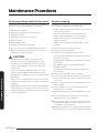
Maintence Procedures 34
Performing the gas leak tests for repair 34
Decommissioning 34
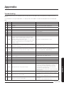
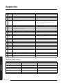
Appendix 35
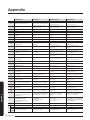
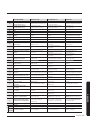
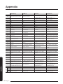
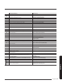
Troubleshooting 35
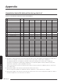
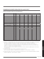
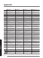
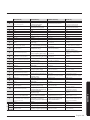
Technical specifications 36
COMMISSION DELEGATED REGULATION (EU) No 626/2011
i)
37
Correct Disposal of This Product
(Waste Electrical & Electronic Equipment)
(Applicable in countries with separate collection systems)
This marking on the product, accessories or literature indicates that the product and its electronic accessories (e.g.
charger, headset, USB cable) should not be disposed of with other household waste at the end of their working life.
To prevent possible harm to the environment or human health from uncontrolled waste disposal, please separate
these items from other types of waste and recycle them responsibly to promote the sustainable reuse of material
resources.
Household users should contact either the retailer where they purchased this product, or their local government
office, for details of where and how they can take these items for environmentally safe recycling.
Business users should contact their supplier and check the terms and conditions of the purchase contract. This
product and its electronic accessories should not be mixed with other commercial wastes for disposal.
For information on Samsung’s environmental commitments and product-specific regulatory obligations, e.g. REACH,
WEEE, Batteries, visit : samsung.com/uk/aboutsamsung/samsungelectronics/corporatecitizenship/data_corner.html

4
Safety Information
English
Safety Information
Safety Information
WARNING
• Hazards or unsafe practices that may result in severe
personal injury or death.
CAUTION
• Hazards or unsafe practices that may result in minor
personal injury or property damage.
Carefully follow the precautions listed below because
they are essential to guarantee the safety of the
equipment.
WARNING
• Always disconnect the air conditioner from the power
supply before servicing it or accessing its internal
components.
• Verify that installation and testing operations are
performed by qualified personnel.
• Verify that the air conditioner is not installed in an
easily accessible area.
General information
WARNING
• Carefully read the content of this manual before
installing the air conditioner and store the manual in
a safe place in order to be able to use it as reference
after installation.
• For maximum safety, installers should always
carefully read the following warnings.
• Store the operation and installation manual in a safe
location and remember to hand it over to the new
owner if the air conditioner is sold or transferred.
• This manual explains how to install an indoor unit
with a split system with two SAMSUNG units. The use
of other types of units with different control systems
may damage the units and invalidate the warranty.
The manufacturer shall not be responsible for
damages arising from the use of non compliant units.
• The manufacturer shall not be responsible for damage
originating from unauthorized changes or the
improper connection of electric and requirements set
forth in the “Operating limits” table, included in the
manual, shall immediately invalidate the warranty.
• The air conditioner should be used only for the
applications for which it has been designed: the
indoor unit is not suitable to be installed in areas
used for laundry.
• Do not use the units if damaged. If problems occur,
switch the unit off and disconnect it from the power
supply.
• In order to prevent electric shocks, fires or injuries,
always stop the unit, disable the protection switch
and contact SAMSUNG’s technical support if the unit
produces smoke, if the power cable is hot or damaged
or if the unit is very noisy.
• Always remember to inspect the unit, electric
connections, refrigerant tubes and protections
regularly. These operations should be performed by
qualified personnel only.
• The unit contains moving parts, which should always
be kept out of the reach of children.
• Do not attempt to repair, move, alter or reinstall the
unit. If performed by unauthorized personnel, these
operations may cause electric shocks or fires.
• Do not place containers with liquids or other objects
on the unit.
• All the materials used for the manufacture and
packaging of the air conditioner are recyclable.
• The packing material and exhaust batteries of the
remote controller(optional) must be disposed of in
accordance with current laws.
• The air conditioner contains a refrigerant that has
to be disposed of as special waste. At the end of its
life cycle, the air conditioner must be disposed of in
authorized centres or returned to the retailer so that
it can be disposed of correctly and safely.
• Do not use means to accelerate the defrost operation
or to clean, other than those recommended by
Samsung.
• Do not pierce or burn.
• Be aware that refrigerants may not contain an odour.
• This appliance is not intended for use by persons
(including children) with reduced physical, sensory
or mental capabilities, or lack of experience and
knowledge, unless they have been given supervision
or instruction concerning use of the appliance by a
person responsible for their safety. Children should
be supervised to ensure that they do not play with
the appliance.

5English
Safety Information
• For use in Europe: This appliance can be used by
children aged from 8 years and above and persons
with reduced physical, sensory or mental capabilities
or lack of experience and knowledge if they have
been given supervision or instruction concerning use
of the appliance in a safe way and understand the
hazards involved. Children shall not play with the
appliance. Cleaning and user maintenance shall not be
made by children without supervision.
Installing the unit
WARNING
IMPORTANT: When installing the unit, always remember
to connect first the refrigerant tubes, then the electrical
lines.
• Upon receipt, inspect the product to verify that
it has not been damaged during transport. If the
product appears damaged, DO NOT INSTALL it and
immediately report the damage to the carrier or
retailer (if the installer or the authorized technician
has collected the material from the retailer.)
• After completing the installation, always carry out a
functional test and provide the instructions on how to
operate the air conditioner to the user.
• Do not use the air conditioner in environments with
hazardous substances or close to equipment that
release free flames to avoid the occurrence of fires,
explosions or injuries.
• Do not install the product in a place where
thermohygrostat is needed (such as server room,
machinery room, computer room, etc.) Those places
do not provide guaranteed operation condition of the
product therefore performance can be poor in these
places.
• Do not install the product in a ship or a vehicle
(such as a campervan). Salt, vibration or other
environmental factor may cause the product
malfunction, electric shock or fire.
• Our units should be installed in compliance with the
spaces shown in the installation manual, to ensure
accessibility from both sides and allow repairs
or maintenance operations to be carried out. The
unit’s components should be accessible and easy to
disassemble without endangering people and objects.
• For this reason, when provisions of the installation
manual are not complied with, the cost required to
access and repair the units (in SAFETY CONDITIONS,
as set out in prevailing regulations) with harnesses,
ladders, scaffolding or any other elevation system
will NOT be considered part of the warranty and will
be charged to the end customer.
• The outdoor unit shall be installed in an open space
that is always ventilated.
• The local gas regulations shall be observed.
• To handle, purge, and dispose the refrigerant, or
break into the refrigerant circuit, the worker should
have a certificate from an industry-accredited
authority.
• While in installation or relocation of the product, do
not mix the refrigerant with other gases including air
or unspecified refrigerant. Failure to do so may cause
pressure increase to result in rupture or injury.
• Do not cut or burn the refrigerant container or
pipings.
• Use clean parts such as manifold gauge, vacuum
pump, and charging hose for the refrigerant.
• Installation must be carried out by qualified personnel
for handling the refrigerant. Additionally, reference
the regulations and laws.
• Be careful not to let foreign substances (lubricating
oil, refrigerant, water, etc.) enter the pipings.
• When mechanical ventilation is required, ventilation
openings shall be kept clear of obstruction.
• For disposal of the product, follow the local laws and
regulations.
• Do not work in a confined place.
• The work area shall be blocked.
• The refrigerant pipings shall be installed in the
position where there are no substances that may
result in corrosion.
• The following checks shall be performed for
installation:
– The charging amount depends on the room size.
– The ventilation devices and outlets are operating
normally and are not obstructed.
– Markings and signs on the equipment shall be
visible and legible.
• Upon leakage of the refrigerant, ventilate the room.
When the leaked refrigerant is exposed to flame, it
may cause generation of toxic gases.

6
Safety Information
English
Safety Information
• Make sure that the work area is safe from flammable
substances.
• To purge air in the refrigerant, be sure to use a
vacuum pump.
• Note that the refrigerant has no odour.
• The units are not explosion proof so they must be
installed with no risk of explosion.
• This product contains fluorinated gases that
contribute to global greenhouse effect. Accordingly,
do not vent gases into the atmosphere.
• For installation with handling the refrigerant(R-32),
use dedicated tools and piping materials. Working
pressure of R-32 is higher than R410A, So failure to
use the dedicated tools and piping materials may
cause rupture or injury. Furthermore, it may cause
serious accidents such as water leakage, electric
shock or fire.
• Servicing shall be performed as recommended by the
manufacturer. In case other skilled persons are joined
for servicing, it shall be carried out under supervision
of the person who is competent in handling
flammable refrigerants.
• For servicing the units containing flammable
refrigerants, safety checks are required to minimise
the risk of ignition.
• Servicing shall be performed following the controlled
procedure to minimize the risk of flammable
refrigerant or gases.
• Do not install where there is a risk of combustible gas
leakage.
• Do not place heat sources.
• Be cautious not to generate a spark as follows:
– Do not remove the fuses with power on.
– Do not disconnect the power plug from the wall
outlet with power on.
– It is recommended to locate the outlet in a high
position. Place the cords so that they are not
tangled.
• If the indoor unit is not R-32 compatible, an error
signal appears and the unit will not operate.
• After installation, check for leakage. Toxic gas may
be generated and if it comes into contact with an
ignition source such as fan heater, stove, and cooker,
cylinders, make sure that only the refrigerant
recovery cylinders are used.
• Never directly touch any accidental leaking
refrigerant. It could result in severe wounds caused
by frostbite.
Power supply line, fuse or circuit
breaker
WARNING
• Always make sure that the power supply is compliant
with current safety standards. Always install the air
conditioner in compliance with current local safety
standards.
• Always verify that a suitable earthing connection is
available.
• Verify that the voltage and frequency of the power
supply comply with the specifications and that the
installed power is sufficient to ensure the operation
of any other domestic appliance connected to the
same electric lines.
• Always verify that the cut-off and protection switches
are suitably dimensioned.
• Verify that the air conditioner is connected to the
power supply in accordance with the instructions
provided in the wiring diagram included in the
manual.
• Always verify that electric connections (cable entry,
section of leads, protections…) are compliant with
the electric specifications and with the instructions
provided in the wiring scheme. Always verify that all
connections comply with the standards applicable to
the installation of air conditioners.
• Devices disconnected from the power supply should
be completely disconnected in the condition of
overvoltage category.
• Be sure not to perform power cable modification,
extension wiring, and multiple wire connection.
– It may cause electric shock or fire due to poor
connection, poor insulation, or current limit
override.
– When extension wiring is required due to power
line damage, refer to Step 4 Optional: Extending
the power cable in the installation manual.

7English
Installation Procedure
Installation Procedure
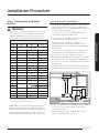
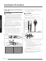
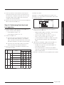
Step 1 Choosing the installation
location
WARNING
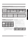
• Because your air conditioner contains R-32 refrigerant,
make sure that it is installed, operated, and stored it in
a room whose floor area is larger than the minimum
required floor area specified in the following table:
Minimum required room area (A, m²)
m (kg)
Ceiling-mounted
type
Wall-mounted
type
Floor-standing
type
≤ 1.842 No requirement
1.843 3.64 4.45 28.9
1.9 3.75 4.58 30.7
2.0 3.95 4.83 34.0
2.2 4.34 5.31 41.2
2.4 4.74 5.79 49.0
2.6 5.13 6.39 57.5
2.8 5.53 7.41 66.7
3.0 5.92 8.51 76.6
3.2 6.48 9.68 87.2
3.4 7.32 10.9 98.4
3.6 8.20 12.3 110
3.8 9.14 13.7 123
4.0 10.1 15.1 136
4.2 11.2 16.7 150
4.4 12.3 18.3 165
4.6 13.4 20.0 180
4.8 14.6 21.8 196
5.0 15.8 23.6 213
5.2 17.1 25.6 230
– m : Total refrigerant charge in the system
– A :
Minimum required room area
• IMPORTANT: it’s mandatory to consider either the
table 1 or taking into consideration the local law
regarding the minimum living space of the premises.
• Minimum installation height of indoor unit is 0.6 m
for floor mounted, 1.8 m for wall, 2.2 m for ceiling.
Installation location requirements
• Do not place the outdoor unit on its side or upside
down. Failing to do so may cause the compressor
lubrication oil to run into the cooling circuit and lead
to a serious damage to the unit.
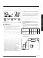
• Install the unit in a well-ventilated location away
from direct sunlight or strong winds.
• Install the unit in a location that would not obstruct
any passageways or thoroughfares.
• Install the unit in a location that would not
inconvenience or disturb your neighbors, as they
could be affected by the noise or the airflow coming
from the unit.
• Install the unit in a location where the pipes and the
cables can be easily connected to the indoor unit.
• Install the unit on a flat, stable surface that can
withstand the weight of the unit. Otherwise, the unit
can generate noise and vibration during operation.
• Install the unit so that the air flow is directed towards
the open area.
• Maintain sufficient clearance around the outdoor unit,
especially from a radio, computer, stereo system, etc.
Fuse
Control
1 m or more
1 m or more
1.5 m or more
1.5 m or more
300 mm
Stereo
Computer etc
Outdoor Unit
200 mm
Air Guide Duct (This product is not provided by Samsung)
Indoor Unit
• Install the unit at a height where its base can be
firmly fixed in place.
• Make sure that the water dripping from the drain
hose runs away correctly and safely.

8
Installation Procedure
English
Installation Procedure
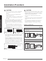
CAUTION
• You have just purchased a system air conditioner
and it has been installed by your installation
specialist.
• This device must be installed according to the
national electrical rules.
• If your outdoor unit exceeds a net weight of 60 kg,
do not install it on a suspended wall, but stand it
on a floor.
• When installing the outdoor unit at the seaside, make
sure that it is not directly exposed to sea breeze. If
you cannot find an adequate place free from direct
sea breeze, construct a protection wall or a protective
fence.
– Install the outdoor unit in a place (such as near
buildings etc.) where it can be prevented from sea
breeze. Failure to do so may cause a damage to
the outdoor unit.
Sea breeze Sea breeze
Sea Sea
Outdoor Unit Outdoor Unit
• If you cannot avoid installing the outdoor unit at the
seaside, construct a protection wall around to block
the sea breeze.
• Construct a protection wall with a solid material such
as concrete to block the sea breeze. Make sure that the
height and the width of the wall are 1.5 times larger
than the size of the outdoor unit. Also, secure a space
larger than 700 mm between the protection wall and
the outdoor unit for exhausted air to ventilate.
Protection wall
Outdoor Unit
Sea breeze
Sea
CAUTION
• Depending on the condition of power supply, unstable
power or voltage may cause malfunction of the parts
or control system. (At the ship or places using power
supply from electric generator...etc)
• Install the unit in a place where water can drain
smoothly.
• If you have any difficulty finding installation location
as prescribed above, contact your manufacturer for
details.
• Be sure to clean the sea water and the dust on the
heat exchanger of the outdoor unit and apply a
corrosion inhibitor on it. (At least once in a year.)
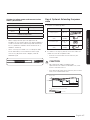
Outdoor unit dimensions
(Unit: mm)
A Type
AC100RXADKG/AC100RXADNG/AC120RXADKG/
AC120RXADNG
998
977
537
528
620
940
330
384
360
675
B Type
AC140RXADKG/AC140RXADNG
620
330
384
360
1210
1185
940
567
558
675

9English
Installation Procedure
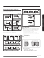
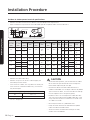
Minimum clearances for the outdoor unit
When installing 1 outdoor unit
(Unit: mm)
300 or more
1500 or more
300 or
more
600 or
more
300 or
more
2000
or more
1500
or more
600
or more
300
or more
1500
or more
300 or
more
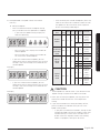
When installing more than 1 outdoor unit
(Unit: mm)
1500
or more
600
or more
3000
or more
3000
or more
300
or more
600
or more
600
or more
1500
or more
300
or more
1500 or more
600
or more
600
or more
300
or more
600
or more
600
or more
600
or more
300
or more
300 or more
300 or more
500 or more 500 or more
CAUTION
• The outdoor unit must be installed according to the
specified distances in order to permit accessibility
from each side, to guarantee correct operation,
maintenance, and repair of the unit.
The components of the outdoor unit must be
reachable and removable under safe conditions for
people and the unit.
WARNING
• Should adopt bar type louver. Don’t use a type of rain
resistance louver.
[Bar type louver] [Rain resistance louver]
• Louver specifications.
– Angle criteria : less than 20°
– Opening ratio criteria : greater than 80%

10
Installation Procedure
English
Installation Procedure
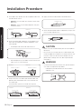
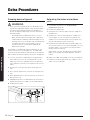
Moving the outdoor unit with wire rope
1 Before carrying the outdoor unit, fasten two wire
ropes of 8 m or longer, as shown in the figure.
2 To prevent damages or scratches effectively, insert
a piece of cloth between the outdoor unit and the
ropes.
3 Move the outdoor unit.
Wire rope
Plate protection
cloth
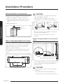
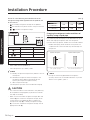
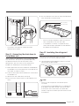
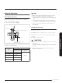
Step 2 Fixing the outdoor unit in place
Install the outdoor unit on a rigid and stable base to
prevent disturbance from any noise caused by vibration.
When installing the unit at a height or in a location
exposed to strong winds, fix the unit securely to a
support (i.e., a wall or a ground).
Fix the outdoor unit with anchor bolts. Make sure that
the anchor bolts are 20 mm or higher from the base
surface.
(Unit : mm)
Anchor bolt hole
CAUTION
• Install a drain outlet at the lowest end around the
base for outdoor unit drainage
• When installing the outdoor unit on the roof,
waterproof the unit and check the ceiling strength.
• Make sure that the wall can support the weights of
the rack and the outdoor unit.
• Install the rack close to the column as much as
possible.
Optional: Fixing the outdoor unit to a wall with
a rack
Soft rubber designed to cut off vibration from
rack to wall. (not supplied with product)
Designed to cut off residual vibration from
outdoor unit to rack. (not supplied with product)
Anchor bolt
Base surface
20 mm
• Install a proper grommet in order to reduce noise and
residual vibration transferred by the outdoor unit
towards the wall.
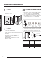
CAUTION
• When installing an air guide duct, be sure to check
the following:
– The screws do not damage the copper pipe.
– The air guide duct is fixed firmly on the guard fan.

11English
Installation Procedure
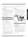
Step 3 Connecting the power cables,
communication cable, and controllers
You must connect the following three electrical cables to
the outdoor unit:
• The main power cable between the auxiliary circuit
breaker and the outdoor unit.
• The outdoor-to-indoor power cable between the
outdoor unit and the indoor unit.
• The communication cable between the outdoor unit
and the indoor unit.
CAUTION
• During installation, make first the refrigerant
connections and then the electrical connections. If
the unit is uninstalled, first disconnect the electrical
cables and then the refrigerant connections.
• Connect the air conditioner to the earthing system
before making the electrical connections.
NOTE
• Especially, if your outdoor unit is the one designed
for Russian and European markets, consult the supply
authority, if necessary, to estimate and reduce the
supply system impedance before installation.
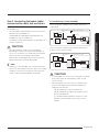
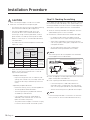
Air conditioning system examples
When using earth leakage circuit breaker (ELCB) for a
single phase
MCCB
1
ELB
Main power
cable
Communication cable
Outdoor-to-indoor power cable
Earthing
Outdoor Unit
OR
Indoor Unit
ELCB
1
When using earth leakage circuit breaker (ELCB) for a
3-phase, 4-wire system (3P4W)
ELB
Main power
cable
Communication cable
Outdoor-to-indoor power cable
Earthing
Outdoor Unit
OR
Indoor Unit
MCCB
3
ELCB
3
CAUTION
• If the outdoor unit is installed in a location vulnerable
to an electric leak or submergence, make sure to
install an ELCB.
• For the product that uses the R-32 refrigerant, be
cautious not to generate a spark by keeping the
following requirements:
– Do not remove the fuses with power on.
– Do not disconnect the power plug from the wall
outlet with power on.
– It is recommended to locate the outlet in a high
position. Place the cords so that they are not
tangled.

12
Installation Procedure
English
Installation Procedure
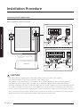
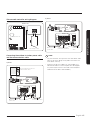
Connecting the main power cable
When using ELB for 1 phase and 3 phase
1(L) 2(N) L1(R) L2(S) L3(T) N
F1 F2
1(L) 2(N) L N
F1 F2
MCCB
ELB
Power supply
Electrical
component box
The appearance of the unit may be
different from the picture depending
on the model.
Indoor Unit
1-phase
3-phase
Main power
cable
Communication cable
Communication
cable
3-phase 4-wire
main power cable
(AC 380V)
Outdoor-to-
indoor power
cable
Outdoor-to-
indoor power
cable
Cable tie
Cable tie
CAUTION
• You should connect the power cable into the power cable terminal and fasten it with a clamp.
• The unbalanced power must be maintained within 2% of supply rating.
If the power is unbalanced greatly, it may shorten the life of the condenser. If the unbalanced power is
exceeded over 4% of supply rating, the indoor unit is protected, stopped and the error mode indicates.
• To protect the product from water and possible shock, you should keep the power cable and the connection cord of
the indoor and outdoor units within ducts. (with appropriate IP rating and material selection for your application)
• Ensure that main supply connection is made through a switch that disconnects all poles, with contact gap of a least 3 mm.
• Devices disconnected from the power supply should be completely disconnected in the condition of overvoltage category.
• Keep distances of 50 mm or more between power cable and communication cable.

13English
Installation Procedure
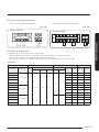
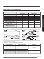
Main power terminal block specifications
• 1-phase terminal block specifications
(Unit: mm)
AC100/120/140RXADKG
1(L) 2(N)
F1 F2
LN
16.3 12 11.4
10.1
• 3-phase terminal block specifications
(Unit: mm)
AC100/120/140RXADNG
1(L) 2(N) L1(R) L2(S) L3(T) N
9.8 14.2 11.4
F1 F2
10.1
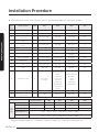
Main power cable specifications
The power cable is not supplied with air conditioner.
• Select the power supply cable in accordance with relevant local and national regulations.
• Wire size must comply with the applicable local and national code.
• Specifications for local wiring power cord and branch wiring are in compliance with local cord.
Single phase
Model Outdoor unit Input current (A) Power supply
Indoor unit Outdoor unit Hz
Voltage range (V) Outdoor unit
Indoor unit Total MCA (A) MFA (A)
Rated Min. Max. Cooling Heating
AC100RN4DKG
AC100RXADKG
50 220 to 240 198 264
24.0 24.0
1.0 25.0 25.0 30.0
AC100RN4PKG
1.5 25.5 25.5 30.0
AC100RNMDKG
2.5 26.5 26.5 30.0
AC100RNCDKG
2.5 26.5 26.5 30.0
AC100RNTDKG
1.6 25.6 25.6 30.0
AC120RN4DKG
AC120RXADKG
1.0 25.0 25.0 30.0
AC120RN4PKG
1.5 25.5 25.5 30.0
AC120RNMDKG
2.5 26.5 26.5 30.0
AC120RNCDKG
2.5 26.5 26.5 30.0
AC140RN4DKG
AC140RXADKG 32.0 32.0
1.0 33.0 33.0 40.0
AC140RN4PKG
1.5 33.5 33.5 40.0
AC140RNMDKG
2.5 34.5 34.5 40.0
AC140RNCDKG
2.5 34.5 34.5 40.0

14
Installation Procedure
English
Installation Procedure
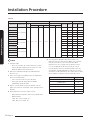
3-phase
Model Outdoor unit Input current (A) Power supply
Indoor unit Outdoor unit Hz
Voltage range (V) Outdoor unit
Indoor unit Total MCA (A) MFA (A)
Rated Min. Max. Cooling Heating
AC100RN4DKG
AC100RXADNG
50 380 to 415 342 456.5 16.1 16.1
1.0 17.1 17.1 17.1
AC100RN4PKG
1.5 17.6 17.6 17.6
AC100RNMDKG
2.5 18.6 18.6 18.6
AC100RNCDKG
2.5 18.6 18.6 18.6
AC100RNTDKG
1.6 17.7 17.7 17.7
AC120RN4DKG
AC120RXADNG
1.0 17.1 17.1 17.1
AC120RN4PKG
1.5 17.6 17.6 17.6
AC120RNMDKG
2.5 18.6 18.6 18.6
AC120RNCDKG
2.5 18.6 18.6 18.6
AC140RN4DKG
AC140RXADNG
1.0 17.1 17.1 17.1
AC140RN4PKG
1.5 17.6 17.6 17.6
AC140RNMDKG
2.5 18.6 18.6 18.6
AC140RNCDKG
2.5 18.6 18.6 18.6
NOTE
1 Voltage range
• Units are suitable for use on electrical systems
where voltage supplied to unit terminal is not
below or above listed range limits.
2 Maximum allowable voltage variation between
phases is 2%.
3 Wire size & type must comply with the applicable
local and national code.
• Wire size: Based on the value of MCA.
• Wire type: 60245 IEC57(IEC) or H05RN-
F(CENELEC) grade or more.
4 MFA is used to select the circuit breaker and the
ground fault circuit interrupter (earth leakage circuit
breaker).
5 MCA represents maximum input current.
• MFA represents capacity which may accept MCA
• Abbreviations
MCA: Min. Circuit Amps. (A)
MFA: Max. Fuse Amps. (A)
6 This equipment complies with IEC 61000-3-12
provided that the short-circuit power Ssc is greater
than or equal to Ssc (*2) at the interface point
between the user’s supply and the public system.
It is the responsibility of the installer or user of
the equipment to ensure, by consultation with the
distribution network operator if necessary, that the
equipment is connected only to a supply with a short-
circuit power Ssc greater than or equal to Ssc(*2).
Model Ssc[MVA]
AC100RXADKG 1.4
AC100RXADNG 2.5
AC120RXADKG 1.9
AC120RXADNG 2.7
AC140RXADKG 1.9
AC140RXADNG 2.5

15English
Installation Procedure
Silence mode controller wiring diagram
Outdoor unit
ASSY Control out
Non-voltage contact
Connecting the outdoor-to-indoor power cable
and the communication cable
1-phase
LN
F1 F2
1(L) 2(N) L N
F1 F2
Outdoor-to-indoor
power cable
For connecting the power and
communication cables
Main power cable Communication cable
Cable tie
Indoor Unit
Outdoor Unit
3-phase
LN
F1 F2
1(L) 2(N) L1(R) L2(S) L3(T) N
F1 F2
Indoor Unit
Outdoor-to-indoor
power cable
3-phase 4-wire main
power cable (AC 380V)
Communication
cable
Cable tie
Outdoor Unit
NOTE
• Lay the electrical wiring so that the front cover does
not rise up when doing wiring work and attach the
front cover securely.
• Ground wire for the indoor unit and outdoor unit
connection cable must be clamped to a soft copper
tin-plated eyelet terminal with M4 screw hole(NOT
SUPPLIED WITH UNIT ACCESSORIES).

16
Installation Procedure
English
Installation Procedure
Outdoor-to-indoor power terminal specifications
• Connect the cables to the terminal board using the compressed ring terminal.
• Cover a solderless ring terminal and a connector part of the power cable and then connect it.
Silver solder
Norminal
dimensions
for cable
(mm²)
Norminal
dimensions
for screw
(mm)
BDd1EFLd2t
Standard
dimension
(mm)
Allowance
(mm)
Standard
dimension
(mm)
Allowance
(mm)
Standard
dimension
(mm)
Allowance
(mm)
Min.
(mm)
Min.
(mm)
Max.
(mm)
Standard
dimension
(mm)
Allowance
(mm)
Min.
(mm)
4/6
4 9.5
±0.2 5.6
+0.3
-0.2
3.4 ±0.2 6
5 20 4.3
+0.2
0
0.9
8 15 9 28.5 8.4
+0.4
0
10 8 15 ±0.2 7.1
+0.3
-0.2
4.5 ±0.2 7.9 9 30 8.4
+0.4
0
1.15
16 8 16 ±0.2 9
+0.3
-0.2
5.8 ±0.2 9.5 13 33 8.4
+0.4
0
1.45
25
812
±0.3 11.5
+0.5
-0.2
7.7 ±0.2 11
15
34
8.4
+0.4
0
1.7
8 16.5 13 8.4
35
816
±0.3 13.3
+0.5
-0.2
9.4 ±0.2 12.5
13 38 8.4
+0.4
0
1.8
8 22 13 43 8.4
50 8 22 ±0.3 13.5
+0.5
-0.2
11.4 ±0.3 17.5 14 50 8.4
+ 0.4
0
1.8
70 8 24 ±0.4 17.5
+0.5
-0.4
13.3 ±0.4 18.5 20 51 8.4
+ 0.4
0
2.0
• Connect the rated cables only.
• Connect using a driver which is able to apply the
rated torque to the screws.
• If the terminal is loose, fire may occur caused by arc.
If the terminal is connected too firmly, the terminal
may be damaged.
Tightening torque (N⋅m)
M4 0.8 to 1.2
M5 2.0 to 3.0
• 1 N⋅m = 10 kgf⋅cm
CAUTION
• When connecting cables, you can connect the cables
to the electrical part or connect them through the
holes below depending on the spot.
• Connect the communication cable between the
indoor and outdoor units through a conduit to protect
against external forces, and feed the conduit through
the wall together with refrigerant piping.
• Remove all burrs at the edge of the knock-out hole
and secure the cable to the outdoor knock-out using
lining and bushing with an electrical insulation such
as rubber and so on.
• Must keep the cable in a protection tube.
• Keep distances of 50mm or more between power
cable and communication cable.
• When the cables are connected through the hole,
remove the Plate bottom.

17English
Installation Procedure
Outdoor-to-indoor power and communication
cables specifications
Indoor power supply
Power supply Max/Min (V) Indoor power cable
1ø, 220-240V,
50 Hz
±10% 1.5 mm²
Ĺ
, 3 wires
Communication cable
0.75 to 1.5 mm², 2 wires
• Power supply cords of parts of appliances for
outdoor use shall not be lighter than polychloroprene
sheathed flexible cord. (Code designation IEC:60245
IEC 57 / CENELEC: H05RN-F or IEC:60245 IEC 66 /
CENELEC: H07RN-F)
• When installing the indoor unit in a computer room
or net work room, use the double shielded (tape
aluminium / polyester braid + copper ) cable of
FROHH2R type.
Step 4 Optional: Extending the power
cable
1 Prepare the following tools.
Tools Spec Shape
Crimping pliers MH-14
Connection sleeve
(mm)
20xØ6.5
(HxOD)
Insulation tape
Width 19
mm
Contraction tube
(mm)
70xØ8.0
(LxOD)
2 As shown in the figure, peel off the shields from the
rubber and wire of the power cable.
• Peel off 20 mm of cable shields from the pre-
installed tube.
CAUTION
• For information about the power cable
specifications for indoor and outdoor units, refer
to the installation manual.
• After peeling off cable wires from the pre-installed
tube, insert a contraction tube.
Power cable
(Unit: mm)
20 20 20
60
120
180
Pre-installed tube for the power cable
(Unit: mm)
20

18
Installation Procedure
English
Installation Procedure
3 Insert both sides of core wire of the power cable into
the connection sleeve.
• Method 1: Push the core wire into the sleeve from
both sides.
• Method 2: Twist the wire cores together and push
it into the sleeve.
Connection sleeve Connection sleeve
Method 1 Method 2
4 Using a crimping tool, compress the two points and
flip it over and compress another two points in the
same location.
• The compression dimension should be 8.0.
Compression
dimension
• After compressing it, pull both sides of the wire to
make sure it is firmly pressed.
Compress it 4 times.
5 mm
Compress it 4 times.
5 mm
Method 1 Method 2
5 Wrap it with the insulation tape twice or more and
position your contraction tube in the middle of the
insulation tape.
Three or more layers of insulation are required.
Method 1 Method 2
Insulation tape
40 mm
35 mm
Insulation tape
6 Apply heat to the contraction tube to contract it.
Contraction tube
7 After tube contraction work is completed, wrap it with
the insulation tape to finish.
Insulation tape
CAUTION
• Make sure that the connection parts are not exposed
to outside.
• Be sure to use insulation tape and a contraction tube
made of approved reinforced insulating materials that
have the same level of withstand voltage with the
power cable. (Comply with the local regulations on
extensions.)
WARNING
• In case of extending the electric wire, please DO NOT
use a round-shaped Pressing socket.
– Incomplete wire connections can cause electric
shock or a fire.

19English
Installation Procedure
Step 5 Connecting the refrigerant pipe
Items
Maximum allowable length
Single Installation DPM Installation
Applicable outdoor unit models
AC100RXAD*G
AC120RXAD*G
AC140RXAD*G
AC100RXAD*G
AC120RXAD*G
AC140RXAD*G
Total pipe length (L1+…+Ln+1+a+b) - - 50 m 75 m
Main pipe (L1) 50 m 75 m 30 m 50 m
Max. distance among indoor units (D) - - 10 m 10 m
Max. length after branch - - 15 m 15 m
Max. height difference between
outdoor and indoor units (h1)
30 m 30 m 30 m 30 m
Max. height difference among
indoor units(h2)
- - 0.5 m 0.5 m
Max Pipe length difference among
indoor units after branch
[L2-L3 or L2-L4 or L2-L5 or a-b or
(a+L2)-(b+L4) or (a+L3)-(b+L5)]
- - 5 m 5 m
• "n" means the number of indoor unit connection of DPM.
indoor
indoor
indoor
outdoor
outdoor
outdoor
indoor
indoor
indoor
indoor
indoor
indoor
indoor
outdoor
L
1
L
1
L
2
L
2
D
D
D
D
h
2
h
2
L
3
L
3
L
4
L
4
L
5
L
1
a
b
D
L
1
L
2
L
3
h
1
h
2
h
1
h
1
h
1
n=1
n=2
n=3
n=4
• Use a joint kit that is only for DPM.
• Temper grade and minimum thickness of the refrigerant pipe
Outer diameter [mm] Minimum thickness [mm] Temper grade
ø6.35 0.7
C1220T-O
ø9.52 0.7
ø12.70 0.8
ø15.88 1.0
ø15.88 0.8
C1220T-1/2H OR C1220T-Hø19.05 0.9
ø22.23 0.9

20
Installation Procedure
English
Installation Procedure
CAUTION
• Be sure to use C1220T-1/2H (Semi-hard) pipe for
more than Ø19.05 mm. If you use C1220T-O (Soft)
pipe for Ø19.05 mm, the pipe may be broken, which
can result in an injury.
Make at least one round:
It will reduce noise and vibration
• The appearance of the unit may be different from the
diagram depending on the model.
CAUTION
• After connecting the pipes with knock-out treatment,
plug the space around the pipes.
• After connecting the pipes, proceed exactly as
directed in the guide to prevent interference with the
internal parts.
• Tighten the nuts to the specified torques. If
overtightened, the nuts could be broken so
refrigerant may leak.
• Protect or enclose refrigerant tubing to avoid
mechanical damage.
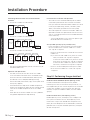
Step 6 Optional: Cutting and aring the
pipes
1 Make sure that you have the required tools available.
(pipe cutter, reamer, flaring tool, and pipe holder)
2 If you wish to shorten the pipes, cut it with a pipe
cutter, taking care to ensure that the cut edge remains
at a 90° angle with the side of the pipe. Refer to
the illustrations below for examples of edges cut
correctly and incorrectly.
Pipe cutter
Pipe
90°
Oblique
Rough
Burr
90
3 To prevent any gas from leaking out, remove all burrs
at the cut edge of the pipe, using a reamer.
4 Slide a flare nut on to the pipe and modify the flare.
D
A
D
45° ±2°
90° ±2°
Pipe
Flare
Flare
R 0.4 to 0.8 mm
L
Outer diameter (D) Depth (A) Flare dimension (L)
ø6.35 mm 1.3mm 8.7 to 9.1 mm
ø9.52 mm 1.8mm 12.8 to 13.2 mm
ø12.70 mm 2.0mm 16.2 to 16.6 mm
ø15.88 mm 2.2mm 19.3 to 19.7 mm
ø19.05 mm 2.2mm 23.6 to 24.0 mm
Pagina se încarcă...
Pagina se încarcă...
Pagina se încarcă...
Pagina se încarcă...
Pagina se încarcă...
Pagina se încarcă...
Pagina se încarcă...
Pagina se încarcă...
Pagina se încarcă...
Pagina se încarcă...
Pagina se încarcă...
Pagina se încarcă...
Pagina se încarcă...
Pagina se încarcă...
Pagina se încarcă...
Pagina se încarcă...
Pagina se încarcă...
Pagina se încarcă...
Pagina se încarcă...
Pagina se încarcă...
Pagina se încarcă...
Pagina se încarcă...
Pagina se încarcă...
Pagina se încarcă...
Pagina se încarcă...
Pagina se încarcă...
Pagina se încarcă...
Pagina se încarcă...
Pagina se încarcă...
Pagina se încarcă...
Pagina se încarcă...
Pagina se încarcă...
-
 1
1
-
 2
2
-
 3
3
-
 4
4
-
 5
5
-
 6
6
-
 7
7
-
 8
8
-
 9
9
-
 10
10
-
 11
11
-
 12
12
-
 13
13
-
 14
14
-
 15
15
-
 16
16
-
 17
17
-
 18
18
-
 19
19
-
 20
20
-
 21
21
-
 22
22
-
 23
23
-
 24
24
-
 25
25
-
 26
26
-
 27
27
-
 28
28
-
 29
29
-
 30
30
-
 31
31
-
 32
32
-
 33
33
-
 34
34
-
 35
35
-
 36
36
-
 37
37
-
 38
38
-
 39
39
-
 40
40
-
 41
41
-
 42
42
-
 43
43
-
 44
44
-
 45
45
-
 46
46
-
 47
47
-
 48
48
-
 49
49
-
 50
50
-
 51
51
-
 52
52


Samsung AC100RXADKG/EU Manualul utilizatorului
- Tip
- Manualul utilizatorului
- Acest manual este potrivit și pentru
în alte limbi
- English: Samsung AC100RXADKG/EU User guide
Lucrări înrudite
-
Samsung AC100RXADKG/EU Manual de utilizare
-
Samsung AC120MXADKH/EU Manual de utilizare
-
Samsung AC100KX4DKH/EU Manualul utilizatorului
-
-
Samsung AC071JXSCEH/EU Manual de utilizare
-
Samsung AC140KXADGH/EU Manualul utilizatorului
-
-
-
Samsung AE140JXYDGH/EU Manualul utilizatorului
-
Samsung AC090HCADKH/EU Manualul utilizatorului
Alte documente
-
Tesla TA36QQCT-1232IAWT Manual de utilizare
-
Tesla TC26P4-0932IA Manual de utilizare
-
Sharp AE-A9NR Instrucțiuni de utilizare
-
Mitsubishi Electric PFFY Series Manual de utilizare
-
DeWalt DPC10RC Manual de utilizare
-
DeWalt DPC10QTC Manual de utilizare
-
LG UV18R.N10 Ghid de instalare
-
 Inventor M3GHP290-12 Portable Air Conditioning Systems Manual de utilizare
-
LG PM05SP Manual de utilizare
-
LG MU5R40 Manual de utilizare
