Inventor M3GHP290-12 Portable Air Conditioning Systems Manual de utilizare
- Tip
- Manual de utilizare

PORTABLE
MODEL:
M3GHP290-12
M3GHP290-12BS
AIR CONDITIONING SYSTEMS
• USER’S MANUAL
• ΕΓΧΕΙΡΙΔΙΟ ΧΡΗΣΗΣ
• MANUAL UTILIZATORULUI
ENGLISH | ΕΛΛΗΝΙΚΑ | ROMANA

2EN
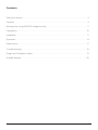
Contents
Safety Precautions ................................................................................................................................................3
Cautions ...................................................................................................................................................................4
Warnings (for using R290/R32 refrigerant only) ...........................................................................................5
Preparation .......................................................................................................................................................... 10
Installation ............................................................................................................................................................ 11
Operation ............................................................................................................................................................. 14
Maintenance ....................................................................................................................................................... 17
Troubleshooting ................................................................................................................................................ 18
Design and Compliance Notes ....................................................................................................................... 19
Sociable Remark ................................................................................................................................................. 20

EN 3
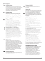
|Safety Precautions
WARNING: “Safety Hazard Symbol”, it is very important to please pay close attention to the
below, to avoid any serious injury.
WARNING: To avoid any serious injuries or possible unit damage, please read carefully and
follow the below safety guidelines:
- The installation of this unit must be according to this manual, as improper installation may cause
water leakage, electrical shock or even a re.
- Use only included parts and accessories, and the specied tools for the installation of your
portable air conditioner. The use of parts that are not included in this package may result to water
leakage, electrical shock, re, injury and possible property damage.
- Be certain that the outlet in use, is properly grounded and that of the correct voltage. The three-
prong power cord is designed to protect against shock. Information regarding voltage may be
found on the nameplate of your unit.
- This unit must be connected to a properly grounded power supply. If the power supply is not
grounded or protected by a fuse or a circuit breaker (the correct fuse is determined by the
maximum current of the unit, which is located on the nameplate of the device) it is strongly
advised to have a professional qualied electrician install the proper power supply.
- Install on a at and sturdy oor. Failure to install in this manner could result in damage, excessive
noise and even vibration.
- This device should be placed clear of any obstructions to ensure its correct and proper function
and to avoid any possible hazards.
- DO NOT use an extension cord or modify the length of the cord in any way, to power the unit.
- DO NOT combine a single power outlet with other electrical appliances. Irregular power supply
may cause electric shock and a possible re.
- DO NOT install this unit in a very humid room such as a bathroom facility or a laundry room.
Excessive exposure to water may cause the internal electrical components to short circuit.
- DO NOT install in a location exposed to a combustible gas, as this could result to a re.
- The device is equipped with casters for easy mobility. It is suggested not to be used on thick
carpets, as this may cause its tripping.
- DO NOT operate this unit if it has been dropped or damaged in any way.
- For models with heating capabilities, there should be at least 1 meter clear space from any
combustible materials.
- Do not touch this unit with wet or damp hands or while barefoot.
- If the portable air conditioner is knocked over while operating, turn o and unplug from the power
socket immediately. Examine the device ensuring there is no visible damage. If you suspect that
the unit has been damaged, it is necessary to contact a technician or customer support for further
assistance.
- In the event of a thunderstorm, it is suggested to turn o the unit as there is the possibility of
damage due to unsteady power supply.
- Your portable air conditioner should be operated in such a manner, so as to be protected from
moisture. Do not position the unit in an area where possible tripping into water may occur. In this
event, unplug immediately.
- All wiring must be performed strictly in accordance to the wiring diagram which is located
internally.
- The circuit board of the unit (PCB) is designed with an overcurrent protection fuse. Specications
of the fuse are printed on the circuit board, in this manner: T3.15A/250V.

4 EN
|Cautions
CAUTIONS
- This appliance can be used by children aged from 8 years and above and persons with reduced
physical, sensory or mental capabilities or lack of experience and knowledge if they have been
given supervision or instruction concerning use of the appliance in a safe way and understand the
hazards involved. Children shall not play with the appliance. Cleaning and user maintenance shall
not be made by children without supervision.
- This appliance is not intended for use by persons (including children) with reduced physical,
sensory or mental capabilities or lack of experience and knowledge, unless supervised, or
given instruction concerning the use of the appliance by a person responsible for their safety.
(Applicable for non- European countries).
- Minors should be supervised to ensure that there is no mishandling od the device. It is strongly
advised that minors should be supervised when around this unit at all times. If the supply cord
person in order to avoid possible hazard.
and disconnected from the mains.
dropped or damaged in any way it should never be used.
- Do not place the power cord under any carpets, rugs, runners or similar coverings, under
furniture or other appliances. The power cord should be placed in such a manner that accidental
tripping may be avoided.
- If the supply cord is damaged, it must be replaced by the manufacturer or its service agent or a
Solid- State speed control device (dimmer).
- This unit must be installed in accordance to the national wiring regulations.
- For the proper maintenance of this unit, please contact an authorized technician.
- If any installation is required, please contact an authorized professional installer.
- The inlet or outlet grilles should never be obstructed.
- This unit should be operated only, as per the instructions of this manual, and not for any other
use.
- In the case of any abnormal behavior (e.g.. a burning smell), disconnect power intermediately and
contact your local dealer.
- Do not operate the buttons of the digital control panel with anything other that your hands.
- Do not turn ON/OFF this device by plugging or unplugging the power cord.
- This unit should never be cleaned with the use of hazardous chemicals. The unit should never be
- Always relocate your portable air conditioner in a vertical position and should always be placed in
a vertical position.
must replace it, in order to avoid a hazard.
- Grip the power plug properly when pulling out of the power socket.
Warning: Low pressure conditions may occur in the area. The device is not recommended for use by
people with chronic respiratory problems.

EN 5
|Warnings (for using R290/R32 refrigerant only)
- Do not use any other means other than the recommended to expedite the defrosting process or
to perform a cleaning of the unit, other than those recommended by the manufacturer.
- This device should never be stored in an area in combination with other ignition sources (for
example: a gas appliance an electrical heater, open ames etc.)
- Do not attempt to penetrate the unit with a tool or try to burn.
- Be extra cautious as refrigerant gas may be odorless.
- Appliance 12000 Btu/h should be installed, operated and stored in a room with a oor area larger
than 11m 2.
Appliance 10000 Btu/h, 9000 Btu/h should be installed, operated and stored in a room with a oor
area larger than 10m 2.
Appliance 12000 Btu/h,10000 Btu/h should be installed, operated and stored in a room with a
oor area larger than 12m 2.
- It is necessary to always comply with national gas regulations.
- Keep air ventilation clear of any obstructions.
- The unit should be placed in storage in such a manner as to prevent any mechanical damage from
occurring.
- Always operate this unit in a well- ventilated area, where the room size corresponds to the
specications of the device for optimal performance.
- Any persons involved with the operation and handling of the refrigerant circuit of this unit,
should be certied by the related accredited industry, and authorized as competent to handle
refrigerants, safely, and in accordance to the safety standards of the industry.
- Servicing should be performed only by a certied technician as per the Mnaufacturers
reccomendations. Any maintenance or repair required, should be performed by skilled personnel
who are competent in the use of ammable refrigerants.
Caution: Risk of re/ ammable materials
(Required for R32/R290 units only)
IMPORTANT NOTE: Please read this manual
carefully prior to installing and operating your
device! It is recommended to keep this manual
for future reference.
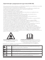
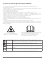
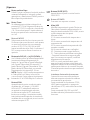
Description of displayed Symbols (*Only applicable to units with R32/R290 Refrigerant)
WARNING This symbol indicates the use of a ammable refrigerant. If any leakage
occurs, or if exposed to an external ignition source, a re risk is possible.
CAUTION This symbol indicates that the user’s manual should be read carefully.
CAUTION This symbol indicates that a professional service technician should handle
this unit with reference to the user’s manual.
CAUTION This symbol indicates the presence of a user’s or installation manual.

6EN
1. Transport of equipment containing
ammable refrigerants See transport
regulations
2. Marking of equipment using signs See local
regulations
3. Disposal of equipment using ammable
refrigerants See national regulations.
4. Storage of equipment/appliances
The storage of equipment should be in
accordance as per the user’s manual.
5. Storage of packed (unsold) equipment
The storage of the package should be
constructed in such a manner that if any
mechanical damage to the equipment will not
result ina leak of the refrigerant.
6. Information on Servicing
1) Checking the area
Upon initial work, regarding systems containing
ammable refrigerants, mandatory safety
checks are required to ensure that the risk
of possible ignition is minimized. Prior to
any repairing to the refrigerant system, the
following
2) Work procedure
Any handling should be performed under a
controlled procedure as to minimize the risk
of ammable gas being present while work is
being performed.
3) General work area
All relative maintenance sta and all others
working in the area, should be clearly
instructed, on the nature of the procedure.
Any maintenance in conned spaces must
be avoided. The space around the work- area
should be securely sectioned o. Conrm that
the conditions within the area, are safe and the
ammable material is controlled.
4) Prior to and during work operation, the
area should be checked and monitored by an
appropriate refrigerant detector, also ensuring
the technicians to be aware of potentially
ammable materials in the atmosphere. It is
very important that the refrigerant detector
being used is suitable for the usage with
ammable refrigerants.
5) Presence of re extinguisher
If any work that involves heat, is to be
conducted, the appropriate re extinguishing
equipment should be always available. A dry
powder or CO2 re extinguisher should be
available adjacent to the charging area.
6) No ignition sources
Work that is in relation to a refrigeration
system which involves exposing any pipe works
that contains or has contained ammable
refrigerant gases should be carried out be
no persons, as they may lead to the risk of a
re.All possible re hazards such as cigarette
smoking, must be kept far away from the site
of repair,installation removing and or disposal,
where the possibility of refrigerant gas may
be released to the atmosphere. Prior to the
performance of any work conducted, the area
around the equipment should be monitored
and checked to be certain that no ammable
hazards or ignition risks are present. NO
SMOKING signs are mandatory and must be
displayed..
7) Ventilated area
Prior to any work performed, be certain that
the area is well ventilated or open. Constant
ventilation while any work is carried out is
necessary. Ventilation should safely disperse
any possible refrigerant leak externally into the
atmosphere.
8) Checks to the refrigeration equipment
Where electrical components are being
changed, they should be t for purpose and
with the correct specications. Manufacturer’s
maintenance and Service Guidelines should
be followed at all times. If there is any doubt,
please consult with the manufacturer’s
Technical Debt for assistance. The following
checks should always be performed in regard
to installations using ammable refrigerants:
The charge size is in accordance with the room
size, in which the refrigerant parts are installed.
Be certain the ventilation is operative and check
the outlets do not have any obstructions.
If there is a use of an indirect refrigerant
circuit, this secondary circuit should be
checked for any refrigerant being present. Any
markings to the equipment should be clear
and visible. Markings and signs that are not
clear should be corrected. Any refrigeration
pipe or components should be installed in
such a manner as to never be exposed to any
substance that may lead to the corrosion of
the refrigerant containing components, unless
these components are designed as resistant to
possible corrosion, or are corroded resistant.
9) Checks to electrical devices
|Warnings (for using R290/R32 refrigerant only)

EN 7
|Warnings (for using R290/R32 refrigerant only)
The repair and the maintenance to the electrical
components must include safety checks and
also component inspection procedures. If there
is any fault, that may compromise the safety of
the work applied, then no electrical supply shall
be connected to the circuit until it is corrected. If
the fault cannot be corrected immediately but it
is necessary to continue operation, a temporary
solution may be applied, such as the reporting
to the owner of the equipment, so all parties are
informed.
Initial safety checks shall include:
Capacitors are discharged, in a safe manner to
avoid any possible sparking. No active electrical
components and wirings are exposed while
charging, recovering or purging the system. That
there is continuity of earth bonding.
7. Repairs to sealed components
1) During any performed repairs to sealed
components, all electrical supplies must be
disconnected from the equipment prior to this
act. If it is necessary to have an electrical supply
to the equipment during its servicing, then a
leak detector should be applied as to warn if
there are any signs of potential hazards present.
2) There should be particular attention to
the following as to ensure, that by working on
electrical components there is no alteration
to the casing in such a way that the level of
protection is aected. This includes damage to
the cables, excessive number of connections,
terminals not designed to original specications,
any damage to seals, the incorrect tting of
glands, etc.
Ensure the unit is mounted securely.
Ensure that the seals or any sealing materials
have not degraded in such a manner as
to no longer serve its purpose, preventing
ammable gases entering the atmosphere. Any
replacement parts should be in accordance as
per the manufacturer’s specications.
NOTE: The use of silicon sealant may aect
the eciency of some types of leak detection
equipment. Safe components do not have to be
isolated prior to working.
8. Repair to intrinsically safe components
Do not apply any permanent inductive or
capacitance loads to the circuit without
ensuring that this will not exceed the
permissible voltage and current, allowed for the
equipment in use. Intrinsically safe components
are the only type that can be worked on, while
live in the presence of ammable atmosphere.
The test apparatus should be at the correct
rating. Any replacement of parts should be as
specied by the Manufacturer, as other parts
may result in an ignition of refrigerant gas from
a possible leak.
9.Cabling
Please check that cables are not subject to wear,
corrosion, excessive pressure, vibration, or any
other adverse environmental eects. Aging or
continual vibration, should also be taken into
account.
10. Detection of ammable refrigerants
Under no circumstance may a potential ignition
source, such as a halide torch or any detector
with the use of a ame, may be used.
11. Leak detection methods
The following leak detection methods are
acceptable for systems containing ammable
refrigerants.
Electronic leak detectors may be used to detect
ammable refrigerants. However, the sensitivity
may not be adequate, or it is possible it may
need re- calibration.
(Detection equipment should be calibrated in
a refrigerant- free area) It should be ensured
that the detector is not a possible ignition
source and is suitable for the refrigerant used.
Leak detection equipment should be set at a
percentage of the LFL of the refrigerant used.
Leak detection equipment should be set at
a percentage of the LFL of the refrigerant
and should be calibrated to the refrigerant
employed and the appropriate percentage
of gas (25% maximum) is conrmed. Leak
detection uids are suitable for use with
most refrigerants but the use of detergents
containing chlorine must be avoided as the
chlorine may react with the refrigerant and
corrode the copper pipe- work. If a leak is
suspected, all ames must be extinguished. If a
leakage of refrigerant is spotted which requires
brazing, all of the refrigerant shall be recovered
from the system, or isolated (by means of
shutting o the valves) in a part of the system
away from the leak. Oxygen free nitrogen (OFN)
should then be purged through the system
both before and during the brazing process.
12. Removal and evacuation
When interfering with the refrigerant circuit

8EN
in order to make any repairs or for any other
purposes, conventional procedures should
be applied. However, it is strongly suggested
that safe practice is followed, and ammability
should be taken under consideration.
The following procedure should be followed as
to:
Remove refrigerant,
Purge the circuit with inert gas,
Evacuate,
Purge again with inert gas,
Open the circuit by performing a cut or brazing.
The refrigerant charge should be recovered
into the assigned and correct recovery
cylinders, The system must be ushed with OFN
to render the unit safe, This process may be
repeated several times. The use of Compressed
air oxygen may not be used for this act.
Flushing may be achieved by breaking the
vacuum in the system with OFN and continuing
to ll until the working pressure has been
achieved, then venting to atmosphere, and
nally pulling down to a vacuum. This process
should be repeated until no refrigerant is left
within the system. When the nal OFN charge
is used, the system shall be vented down to
atmospheric pressure to enable any work to be
performed. This operation is absolutely crucial
if brazing operations on the pipe- work are
intended to take place.
Ensure that the outlet for the vacuum pump is
not close to any ignition sources and there is
plenty of ventilation available.
13. Charging procedures
In addition to conventional charging
procedures, the following requirements should
be followed.
Ensure that the contamination of dierent
refrigerants does not occur when using
charging equipment. Hoses or lines shall be as
short as possible to minimise t he amount of
refrigerant contained in them.
Cylinders shall be kept in an upright position.
Ensure that the refrigeration system is
earthed prior to charging the system with any
refrigerant.
Label the system when charging is complete (if
not labeled already).
Extreme care mustl be taken not to overll
the refrigeration system. Prior to recharging
the system, it must be pressure tested with
OFN. The system must also be leak tested
on completion of charging but prior to
commissioning. A follow up leak test should be
carried out prior to leaving the site.
14. Decommissioning
Before carrying out this procedure, it is
essential that the technician is completely
familiar with the equipment and all its details.
It is considered as good practice that all
refrigerants are recovered safely. Prior to the
task being carried out, an oil and refrigerant
sample shall be taken, in the event that analysis
is required prior to re- use of reclaimed
refrigerant. It is essential that electrical power is
available before the task is commenced.
a) Become familiar with the equipment and its
operation.
b) Electrically isolate the system.
c) Before attempting this procedure please
ensure that: Mechanical handling equipment
is available, if required, for handling refrigerant
cylinders;
All personal protective equipment is available
and being used correctly; The recovery process
is supervised at all times by a competent
person;
Recovery equipment and cylinders conform to
the appropriate standards.
d) Pump down refrigerant system, if possible.
e) If a vacuum is not possible, make a manifold
so that refrigerant can be removed from
various parts of the system.
f) Make sure that cylinder is situated on the
scales before recovery takes place.
g) Start the recovery machine and operate in
accordance with manufacturer's instructions.
h) Do not overll cylinders. (No more than 80 %
volume liquid charge).
i) Do not exceed the maximum working
pressure of the cylinder, even temporarily.
j) When the cylinders have been lled correctly
and the process completed, make sure that the
cylinders and the equipment are removed from
site promptly and all isolation valves on the
equipment are closed o.
k) Recovered refrigerant shall not be charged
into another refrigeration system unless it has
been cleaned and checked.
15. Labelling
Equipment must be labelled stating that it
has been de- commissioned and emptied of
|Warnings (for using R290/R32 refrigerant only)

EN 9
refrigerant. The label must be dated and signed.
Ensure that there are labels on the equipment
stating the equipment contains ammable
refrigerant.
16. Recovery
When removing refrigerant from a system,
either for servicing or decommissioning,
it is recommended good practice that all
refrigerants are removed in a safe manner.
When transferring refrigerant into cylinders,
ensure that only appropriate refrigerant
recovery cylinders are employed.
Ensure that the correct number of cylinders
for holding the total system charge is available.
All cylinders to be used are designated for
the recovered refrigerant and labelled for
that refrigerant (i.e. special cylinders for
the recovery of refrigerant). Cylinders shall
be complete with pressure relief valve and
associated shut- o valves in good working
order. Empty recovery cylinders are evacuated
and, if possible, cooled before recovery
occurs.
The recovery equipment shall be in good
working order with a set of instructions
concerning the equipment that is at hand and
shall be suitable for the recovery of ammable
refrigerants. In addition, a set of calibrated
weighing scales shall be available and in good
working order. Hoses shall be complete with
leak- free disconnect couplings and in good
condition. Before using the recovery machine,
check that it is in satisfactory working order,
has been properly maintained and that any
associated electrical components are sealed
to prevent ignition in the event of a refrigerant
release. Consult manufacturer if in doubt.
The recovered refrigerant shall be returned to
the refrigerant supplier in the correct recovery
cylinder, and the relevant Waste Transfer
Note arranged. Do not mix refrigerants in
recovery units and especially not in cylinders.
If compressors or compressor oils are to
be removed, ensure that they have been
evacuated to an acceptable level to make
certain that ammable refrigerant does not
remain within the lubricant. The evacuation
process shall be carried out prior to returning
the compressor to the suppliers. Only electric
heating to the compressor body shall be
employed to accelerate this process. When oil
is drained from a system, it shall be carried out
safely.
Important Note Regarding Fluorinated
Gasses
- Fluorinated greenhouse gases are contained
in rmly sealed equipment. For specic
information on the type, the amount and the
CO2 equivalent in tonnes of the uorinated
greenhouse gas (on some models), please refer
to the relevant label on the unit itself.
- Installation, service, maintenance and repair of
this unit must be performed only by a certied
technician.
- Unit un- installation and the recycling of, must
be performed by a certied technician.
|Warnings (for using R290/R32 refrigerant only)

10 EN
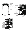
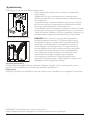
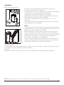
|Preparation
rear
MODEL A
MODEL B
power plug socket
power cord buckle
bottom tray
drain outlet
power cord outlet
drain outlet
(only for pump
heating mode)
upper air filter
(behind the grille)
upper air intake
air outlet
lower air filter
lower air intake
drain outlet
front
rear
control panel
handle
(both sides)
horizontal louver
blade
(swing automatically)
Caster
power plug socket
power cord buckle
vent control
bottom tray
drain outlet
power cord outlet
drain outlet
(only for pump
heating mode)
upper air filter
(behind the grille)
upper air intake
air outlet
lower air filter
lower air intake
drain outlet
Panel
SCALE 0.500

EN 11
|Installation|Installation
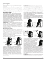
Choosing The Right Location
Tools Needed
Medium Philips screwdriver; - Tape measure or ruler; - Knife or scissors; - Saw (optional, to shorten
window adaptor for narrow windows).
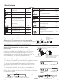
Accessories
Check your window size and choose the t window slider.
50cm
19.7inch
Recommend Installation
NOTE: Items with * are optional. Slight variations in design may occur.
rear
MODEL A
MODEL B
power plug socket
power cord buckle
bottom tray
drain outlet
power cord outlet
drain outlet
(only for pump
heating mode)
upper air filter
(behind the grille)
upper air intake
air outlet
lower air filter
lower air intake
drain outlet
front
rear
control panel
handle
(both sides)
horizontal louver
blade
(swing automatically)
Caster
power plug socket
power cord buckle
vent control
bottom tray
drain outlet
power cord outlet
drain outlet
(only for pump
heating mode)
upper air filter
(behind the grille)
upper air intake
air outlet
lower air filter
lower air intake
drain outlet
Panel
SCALE 0.500
- The air conditioner should be placed on a rm foundation to
minimize noise and vibration. For safe and secure positioning,
place the unit on a smooth, level oor strong enough to
support the unit.
- The unit must be placed near a properly rated grounded
outlet.
- Allow at least 30cm of space from the wall for ecient air-
conditioning.
- Never obstruct the air inlet or outlet of the unit.
NOTE:
All the illustrations in this manual are for explanatory purposes
only. Your air conditioner may be slightly dierent. The actual
shape and size may vary.
The unit can be controlled by the unit control panel alone
or with the remote controller. This manual does not include
Remote Controller Operations, see the "Remote Controll
Illustration" packed with the unit for details.
There is the possibility of dierences between the user’s
manual and the illustrated photos of the remote control,
always refer to the manual for information.

12 EN
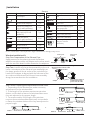
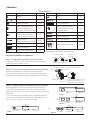
Europe
Part Description Quantity
Unit Adaptor
1 pc
Exhaust Hose
1 pc
*
Window Slider Adaptor
1 pc
*
Wall Exhaust Adaptor A
(only for wall installation)
1 pc
*
Wall Exhaust Adaptor B
(with cap) (only for wall
installation)
1 pc
*
Screw and anchor
(only for wall installation)
4 set
*
Window Slider A
1 pc
*
Window Slider B
1 pc
Power Cord Buckle
1 pc
Part Description Quantity
*
Bolt
1 pc
*
Security Bracket and Screw
1 set
Drain Hose
1 pc
Drain Hose Adaptor(only for
heat pump mode)
1 pc
*
Foam Seal A (Non- adhesive)
2 pc
*
Foam Seal B (Adhesive)
2 pc
*
Foam Seal C (Adhesive)
1 pc
ON/OFF
TEMP
SHORT
CUT
TIMER
ON
TIMER
OFF
MODE
FAN
SLEEP SWIN G LED
Remote Controller
and Battery
1set
NOTE: Items with * are optional. Slight variations in design may occur.
|Installation
Unit adaptor
Window slider
adaptor
Exhaust hose
Press into Press into
Exhaust hose
assembly
or
Make sure the hook of the adaptor is aligned
with the hole seat of the air outlet.
Hook Hole Seat
Lower groove
adaptor Make sure the adaptor is
inserted into the lower
groove of the air outlet.
Window slider A
MODEL A
MODEL A
MODEL B
MODEL B
Window slider B
Bolt
Window slider A Window slider B
Bolt
or
or
Window slider A Window slider B Window slider C
Bolts
Window slider A Window slider B Window slider C
Bolts
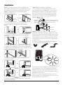
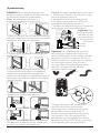
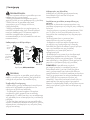
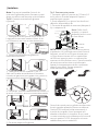
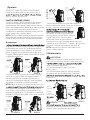
Window Installation Kit
Step One: Preparation of the Exhaust Pipe
Apply pressure to the exhaust pipe and the window
adaptor one side, and the unit adaptor on the other, attach
with the use of the elastic buckles located on the adaptors.
Step Two: Install the Exhaust hose assembly to the unit
Insert unit adaptor of the Exhaust hose assembly into
the lower groove of the air outlet of the unit while the
hook of the adaptor is aligned with the hole seat of the
air outlet and slide down the Exhaust hose assembly
along the arrow direction for installation.
Step Three: Preparing the Adjustable Window Slider
1. Depending on the window size, make necessary
adjustments on the window slider.
2. If the length of the window requires two window
sliders, use the bolt to fasten the window sliders once
they are adjusted to the proper length.
3. For some models, if the length of the window
requires three window sliders(optional), use two bolts
to fasten the window sliders once they are adjusted to
proper length.

EN 13
2 Screws
Security Bracket
Foam seal B
(Adhesive type-shorter)
Foam seal A
(Adhesive type)
Window slider A
Window slider B
(if required)
Foam seal C
(Non-adhesive type) Foam seal C
(Non-adhesive type)
2 Screws
Security
Bracket
or
or
or
or
or
or
MODEL A
MODEL B
Foam seal B
(Adhesive type-shorter)
Foam seal A
(Adhesive type)
Window slider A
Window slider B
(if required)
VENT CONTROL feature
CLOSE
OPEN
max 120cm or 47 inch
min 30cm or 12 inch
Expansion anchor
position
Adaptor cap
Wall Exhaust
Adaptor B
|Installation|Installation
Note: Once the Exhaust Hose assembly and
Adjustable Window Slider are prepared, choose
from one of the following installation methods.
Type 1: Hung Window or Sliding Window
Installation (optional)
Type 2: Wall Installation (optional)
1.Cut a 125mm (4.9inch) hole into the wall
for the Wall Exhaust Adaptor B. 2.Secure the
Wall Exhaust Adaptor B to the wall using the
four Anchors and Screws provided in the kit.
3.Connect the Exhaust Hose Assembly (with
Wall Exhaust Adaptor A) to the Wall Exhaust
Adaptor B.
1. Cut the foam seal (adhesive type) to the
proper length and attach it to the window
frame.
2. Attach the window slider kit to the window
opening.
4.If desired, install the security bracket with 2
screws as shown.
5.Insert the window slider adaptor into the hole
of the window slider.
3.Cut the non- adhesive foam seal C strip to match
the width of the window. Insert the seal between
the glass and the window frame to prevent air and
insects from getting into the room.
Note: Cover the hole
using the adaptor cap
when not in use.
Note: To ensure proper function, DO NOT
overextend or bend the hose. Make sure that
there is no obstacle around the air outlet of the
exhaust hose (in the range of 500mm) in order
to the exhaust system works properly. All the
illustrations in this manual are for explanation
purpose only.
Your air conditioner may be slightly dierent.
The actual shape shall prevail.
The Vent Control is located at the back of the
air conditioner. The OPEN position removes
stale air from the room and exhausts it to the
outside. Fresh air is drawn in through normal
passages in the home.
When not need to circulate the room air, set
Vent Control to CLOSE position. This function is
only applicable for MODEL B.

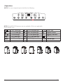
14 EN
HEAT mode light HIGH fan speed light
MED fan speed light
LOW fan speed light
AUTO fan speed light
SLEEP light
Degrees Celsius
Degrees Fahrenheit
LED display
I SENSE light
FILTER light
COOL mode light
FAN mode light
DRY mode light
AUTO mode light
|Operation
NOTE: ION, WIRELESS features are not available. ION is not applicable
for R32/R290 units.
NOTE: The control panel may be look like the following:

EN 15
|Operation
HEAT mode light HIGH fan speed light
MED fan speed light
LOW fan speed light
AUTO fan speed light
ION light
SLEEP light
Degrees Celsius
Degrees Fahrenheit
LED display
FOLLOW ME light
FILTER light
COOL mode light
FAN mode light
DRY mode light
AUTO mode light
WIRELESS light
Swing button
Used to initiate the Auto swing feature. When
the operation is ON, press the SWING button
can stop the louver at the desired angle.
Timer button
Used to initiate the AUTO ON start time and
AUTO OFF stop time program, in conjuction
with the + & - buttons. The timer on/o
indicator light illuminates under the timer
on/o settings.
Mode button
Choose the desired operating mode. By
pressing the MODE button each time an
operation is selected in the following order:
AUTO, COOL, DRY, FAN and HEAT (cooling
only models without). Indication led will
illuminate under the desired MODE setting.
Up (+) and Down (- ) buttons
Used to adjust (increasing/decreasing)
temperature settings in 1°C/1°F (or 2 °F)
increments in a range of 17°C/62°F to
30°C/86°F (or 88°F) or the TIMER setting in a
range of 0~24hrs.
NOTE: The remote control may display the
temperature in both Fahrenheit or Celsius.
To change press and hold the up/down
buttons for 3 sec.
Fan
Control the fan speed. Press to select the
fan speed in four steps- LOW, MED, HIGH
and AUTO. The fan speed indicator light
illuminates under dierent fan settings.
When select AUTO fan speed, all the fan
indicator lights turn dark. On some models,
when select AUTO fan speed, all the fan
indicator lights illumiante(optional).
Sleep(Eco) button
Used to initiate the SLEEP/ECO operation.
Power button
Power switch on/o.
LED display
Shows the set temperature in °C or °F
("°F" no display for some models) and the
Auto- timer settings. While on DRY and FAN
modes, it shows the room temperature.
Shows Error codes and protection code:
E1- Room temperature sensor error.
E2- Evaporator temperature sensor error.
E3- Condenser temperature sensor error
(on some models).
E4- Display panel communication error.
EC- Refrigerant leakage detection
malfunction (on some models).
P1- Bottom tray is full- Connect the drain
hose and drain the collected water away.If
protection repeats,call for service.
Note: When one of the above malfunctions
occurs, turn o the unit, and check for
any obstructions. Restart the unit, if the
malfunction is still present, turn o the
unit and unplug the power cord. Contact
the manufacturer or its service agents or a
similar qualied person for service.
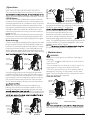
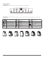
Exhaust hose installation
The exhaust hose and its adaptor should
be installed or removed according to the
usage mode. Under COOL,HEAT(heat pump
type) or AUTO mode the exhaust hose must
be installed, under FAN,DEHUMIDIIFY or
HEAT(electrical heat type) the exhaust hose
should be removed.

16 EN
SCALE 0.500
SCALE 0.500
Remove the air filter
Upper filter
(take out)
Remove the
screw,then
take the lower
filter out.
MODEL A MODEL B
MODEL A MODEL B
MODEL A MODEL B
√
drain hose
adaptor
Continuous
drain hose
Remove the
lower drain plug
√
drain hose
adaptor
Continuous
drain hose
Remove the
lower drain plug
SCALE 0.500
Remove the
upper drain plug
√
Continuous
drain hose
Remove the
upper drain plug
√
Continuous
drain hose
Uper air filter
(take out)
Lower air filter
(take out)
SCALE 0.500
SCALE 0.500
SCALE 0.500
X
drain hose
adaptor
Press the power
cord buckle into
the rear cover.
drain hose
adaptor
√
delivery lift <1.8m
Operation Instructions
COOL operation
- Press the "MODE" button until the "COOL" indicator
light comes on.
- Press the ADJUST buttons "+" or "- " to select your
desired room temperature. The temperature can be set
within a range of 17°C~30°C/62°F~86°F(or 88°F).
- Press the "FAN SPEED" button to choose the fan
speed.
HEAT operation(cooling only models without)
- Press the "MODE" button until the "HEAT" indicator
light comes on.
- Press the ADJUST buttons "+" or " - " to select your
desired room temperature. The temperature can be set
within a range of 17°C~30°C/62°F~86°F(or 88°F).
- Press the "FAN SPEED" button to choose the fan
speed. For some models, the fan speed can not be
adjusted under HEAT mode.
DRY operation
- Press the "MODE" button until the "DRY" indicator light
comes on.
- Under this mode, you cannot select a fan speed or
adjust the temperature. The fan motor operates at LOW
speed.
- Keep windows and doors closed for the best
dehumidifying eect.
- Do not put the duct to window.
AUTO operation
- When you set the air conditioner in AUTO mode, it
will automatically select cooling, heating(cooling only
models without), or fan only operation depending on
what temperature you have selected and the room
temperature.
- The air conditioner will control room temperature
automatically round the temperature point set by you.
- Under AUTO mode, you can not select the fan speed.
NOTE: Under AUTO mode, both the AUTO mode and
the actual operation mode indicator lights illuminate for
some models.
FAN operation
- Press the "MODE" button until the"FAN " indicator light
comes on.
- Press the "FAN SPEED" button to choose the fan
speed. The temperature can not be adjusted.
- Do not put the duct to window.
TIMER operation
- When the unit is on, press the Timer button will initiate
the Auto- o stop program, the TIMER OFF indicator
light illuminates. Press the UP or down button to select
the desired time. Press the TIMER button again within 5
seconds, the Auto- on start program is initiated.
And the TIMER ON indicator light illuminates. Press the
up or down button to select the desired Auto- on start
time.
When the unit is o, press the Timer button to initiate
the Auto- on start program, press it again within 5
seconds will initiate the Auto- o stop program.
- Press or hold the UP or DOWN button to change the
Auto time by 0.5 hour increments, up to 10 hours, then
at 1 hour increments up to 24 hours. The control will
count down the time remaining until start.
- The system will automatically revert back to display the
previous temperature setting if there is no operation in
a 5 seconds period.
- Turning the unit ON or OFF at any time or adjusting the
timer setting to 0.0 will cancel the Auto Start/Stop timer
program.
SLEEP (ECO) operation
- Press this button, the selected temperature will
increase (cooling) or decrease(heating) by 1°C/2°F(or
1°F) 30 minutes. The temperature will then increase
(cooling) or decrease (heating) by another 1°C/2°F(or
1°F) after an additional 30 minutes. This new
temperature will be maintained for the next 7 hours,
after the duration of the above time frame the unit will
return to the initial set temperature and ending the
SLEEP mode. NOTE: This feature is not available under
DRY or FAN mode.
Other features
AUTO- RESTART
In the event of power loss the unit will regain operation,
once power resumes, with the last settings.
AIR FLOW DIRECTION ADJUSTMENT
The louver can be adjusted automatically. Adjust the air
ow direction automatically:
- When the Power is ON, the louver opens fully.
- Press the SWING button on the panel or remote
controller to initiate the Auto swing feature. The louver
willl swing up and down automatically.
- Please do not adjust the louver manually.
|Operation

17
SCALE 0.500
SCALE 0.500
Remove the air filter
Upper filter
(take out)
Remove the
screw,then
take the lower
filter out.
MODEL A MODEL B
MODEL A MODEL B
MODEL A MODEL B
√
drain hose
adaptor
Continuous
drain hose
Remove the
lower drain plug
√
drain hose
adaptor
Continuous
drain hose
Remove the
lower drain plug
SCALE 0.500
Remove the
upper drain plug
√
Continuous
drain hose
Remove the
upper drain plug
√
Continuous
drain hose
Uper air filter
(take out)
Lower air filter
(take out)
SCALE 0.500
SCALE 0.500
SCALE 0.500
X
drain hose
adaptor
Press the power
cord buckle into
the rear cover.
drain hose
adaptor
√
m8.1< tfil yreviled
WAIT 3 MINUTES BEFORE RESUMING OPERATION
Once the unit has stopped its operation, it can not be re-
device. Operation will automatically restart after 3 minutes.
I SENSE feature
The I SENSE function enables the remote control to
measure the temperature at its current location and
send this signal to the air conditioner every 3 minutes
interval. Measuring the ambient temperature from
the remote control (instead of using the indoor unit it-
self) will enable the portable air conditioner to opti-
mize the temperature around you and ensure maxi-
mum comfort.
NOTE:
For optimal results keep the remote pointing to
towards the unit and avoid any obstacles between the
unit and the remote that could possibly block the signal.
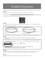
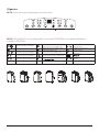
Water drainage
- When under dehumidifying mode, remove the drain
plug for the back of the unit and install the drain con-
nector (5/8 universal female mender) with a 3/4 hose
(may be purchased locally). For models without the
drain connector, please attach the drain hose to the
outlet, while placing the other side of the hose directly
During heating pump mode, remove the lower drain
plug from the back of the unit, install the drain connec-
tor(5/8" universal female mender) with 3/4" hose(local-
ly purchased). For the models without drain connector,
just attach the drain hose to the hole. Place the open
end of the Hose adaptor directly over the drain area in
NOTE: Βe certain the hose is secure without any
leaking. Direct the hose toward the drain, in such a
manner that there are no breaks or bents securing
. Do never let it up.
(See Figs with ). When the continuous drain hose is
prevent possible leakage.
- When the water level of the bottom tray reaches a
predetermined level, the unit beeps 8 times; the digi-
tal display area shows “PI”. At this time
process will immediately stop. Howev-
er, the fan motor will continue to op-
erate (this is normal). Carefully move
the unit to a drain location, remove the
bottom drain plug and let the water
drain . Re- install the bottom drain plug and restart the
machine until the “PI” symbol disappears. If the error
persists, please call for service.
NOTE: -
ly to prevent leakage before using the unit.
| Maintenance
WARNING:
- Be sure to unplug the unit before cleaning or
servicing
- DO NOT use ammable liquids or chemicals to
clean the unit.
- Do not wash the unit directly under a tap or us-
ing a hose as it may cause electrical shock.
- DO NOT operate this unit if the power cable is
damaged in any way. If the power cord is dam-
aged it must be replaced from the product man-
ufacturer and never repaired.
Clean the Air Filter
CAUTION
dirt and lint will clog it and reduce performance.
|Operation
SCALE 0.500
SCALE 0.500
Remove the air filter
Upper filter
(take out)
Remove the
screw,then
take the lower
filter out.
MODEL A MODEL B
MODEL A MODEL B
MODEL A MODEL B
√
drain hose
adaptor
Continuous
drain hose
Remove the
lower drain plug
√
drain hose
adaptor
Continuous
drain hose
Remove the
lower drain plug
SCALE 0.500
Remove the
upper drain plug
√
Continuous
drain hose
Remove the
upper drain plug
√
Continuous
drain hose
Uper air filter
(take out)
Lower air filter
(take out)
SCALE 0.500
SCALE 0.500
SCALE 0.500
X
drain hose
adaptor
Press the power
cord buckle into
the rear cover.
drain hose
adaptor
√
m8.1< tfil yreviled
SCALE 0.500
SCALE 0.500
Remove the air filter
Upper filter
(take out)
Remove the
screw,then
take the lower
filter out.
MODEL A MODEL B
MODEL A MODEL B
MODEL A MODEL B
√
drain hose
adaptor
Continuous
drain hose
Remove the
lower drain plug
√
drain hose
adaptor
Continuous
drain hose
Remove the
lower drain plug
SCALE 0.500
Remove the
upper drain plug
√
Continuous
drain hose
Remove the
upper drain plug
√
Continuous
drain hose
Uper air filter
(take out)
Lower air filter
(take out)
SCALE 0.500
SCALE 0.500
SCALE 0.500
X
drain hose
adaptor
Press the power
cord buckle into
the rear cover.
drain hose
adaptor
√
m8.1< tfil yreviled

18 EN
|Maintenance
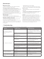
| Troubleshooting
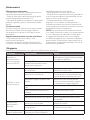
Maintenance Tips
- Clean the air lter every two weeks to prevent
inferior fan operation due to dust.
- The water collection tray must be drained
immediately in the event that the error P1 appears
on the digital control panel, and also before
storage to prevent the possibility of mold growth.
- In households with animals, you will have to
periodically wipe down the grill to prevent blocked
airow due to animal hair.
Clean the Unit
Use a damp lint- free cloth to clean the unit
enclosure. Dry with a clean and lint free cloth cloth.
Store the unit when not in use
- Drain the unit's water collection tray as per the
instructions in the following section.
- Operate the device on FAN mode for 12 hours in
a warm room to dry and prevent the possibility of
mold growth.
- Power o the unit and unplug.
- Clean the air lter as per the instructions in the
previous section. Reinstall the clean and dry lter
before storing.
- Batteries from the remote control should be
removed.
- Store in a cool, shady area. Any exposure directly
to sunlight or in extreme heat situations may
minimize the lifespan of this device.
NOTE: The main chassis and front of the unit
may be cleaned with by using a lint- free cloth and
soapy water (using a mild detergent) Dry with a
clean cloth. The use of harsh cleansers, or the
waxing and polishing of the unit is strongly not
advised. When cleaning the digital control panel
be certain the cloth is dry as any water around the
controls may cause damage to the unit.
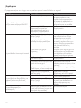
Problem Possible Cause Troubleshooting
Unit does not turn on
when pressing ON/OFF
button
P1 Error Code The Water Collection Tray is full.
Turn o the unit, drain the water
from the Water Collection Tray and
restart the unit.
In COOL mode: room
temperature is lower than the
set temperature
Reset the temperature
Unit does not cool well
The air lter is blocked with dust
or debris
Turn o the unit and clean the lter
according to instructions
Exhaust pipe is not connected
or is blocked
Turn o the unit, disconnect the
hose, check for blockage and
reconnect the hose
The unit is low on refrigerant Call a service technician to inspect
the unit and top o refrigerant
Temperature setting is too high Lower the set temperature
The windows and doors in the
room are open
Conrm all windows and exits are
shut
The room area is too large Double- check the cooling area
There are heat sources inside
the room
Remove the heat sources if
possible
The unit is noisy and
vibrates too much
The ground is not level Place the unit on a at, level surface
The air lter is blocked with dust
or debris
Turn o the unit and clean the lter
according to instructions
The unit makes a gurgling
sound
This sound is caused by the ow
of refrigerant inside the unit
This is normal
Please refer to the below prior to contacting customer support.

EN 19
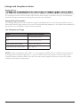
|Design and Compliance Notes
Design Notice:
prior notice, for the improvement of the product. Always consult with the after sales department or
the manufacturer for further details. Manuals are also subject to updates and you should always
check for the latest version by visiting the manufacturer’s website.
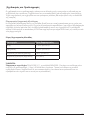
Energy Rating Information
The energy rating of this unit is based on typical installation with the use of the provided, and not
extended, exhaust pipe, without the use of the window slider adaptor or the wall exhaust adaptor A
(as shown in the Installation section of this manual).
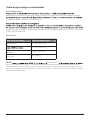
Unit Temperature Range
Mode Temperature Range
Cool17- 35°C (62- 95°F)
Dry13- 35°C (55- 95°F)
Heat (pump heat mode) 5- 30°C (41- 86°F)
Heat (electrical heat mode) 30°C (86°F)
NOTE: To be in compliance EN 61000- 3- 11, the product M3GHP290-12 shall be connected only
to a supply of the system impedance: | Zsys|=0.348 ohms or less. Before connect the product
to public power network, please consult your local power supply authority to ensure the power
network meet above requirement.

20 EN
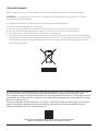
|Sociable Remark
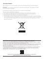
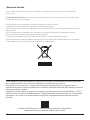
When using this unit in the European countries, the following information must be followed:
DISPOSAL: Do not dispose this product as unsorted municipal waste. This appliance requires
special treatment for disposal.
It is prohibited to dispose of this appliance in domestic household waste.
There are several possibilities for disposal:
A. Your local municipality has established free collection systems for electronic waste.
B. Your local retailer will take back the old product with the purchase of a new product.
C. The manufacture will take back the old appliance for disposal.
D. The old products contain valuable resources and sometimes can be sold to scrap metal dealers.
Do not dispose this product randomly into the environment. The hazardous substances can leak
into the ground- water supply and nd their way into the food chain, endangering your health
and the environment.
All the pictures in the manual are for explanatory purposes only. The actual shape of the unit
you purchased may be slightly dierent, but the operations and functions are the same.
The company may not be held responsible for any misprinted information. The design and the
specications of the product for reasons, such as product improvement, are subject to change
without any prior notice.
Please consult with the manufacturer at +30 211 300 3300 or with the Sales agency for further
details. Any future updates to the manual will be uploaded to the service website, and it is
advised to always check for the latest version.
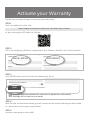
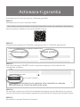
Scan here to download the latest version of this manual.
www.inventorairconditioner.com/media- library
Pagina se încarcă...
Pagina se încarcă...
Pagina se încarcă...
Pagina se încarcă...
Pagina se încarcă...
Pagina se încarcă...
Pagina se încarcă...
Pagina se încarcă...
Pagina se încarcă...
Pagina se încarcă...
Pagina se încarcă...
Pagina se încarcă...
Pagina se încarcă...
Pagina se încarcă...
Pagina se încarcă...
Pagina se încarcă...
Pagina se încarcă...
Pagina se încarcă...
Pagina se încarcă...
Pagina se încarcă...
Pagina se încarcă...
Pagina se încarcă...
Pagina se încarcă...
Pagina se încarcă...
Pagina se încarcă...
Pagina se încarcă...
Pagina se încarcă...
Pagina se încarcă...
Pagina se încarcă...
Pagina se încarcă...
Pagina se încarcă...
Pagina se încarcă...
Pagina se încarcă...
Pagina se încarcă...
Pagina se încarcă...
Pagina se încarcă...
Pagina se încarcă...
Pagina se încarcă...
Pagina se încarcă...
Pagina se încarcă...
Pagina se încarcă...
Pagina se încarcă...
Pagina se încarcă...
Pagina se încarcă...
-
 1
1
-
 2
2
-
 3
3
-
 4
4
-
 5
5
-
 6
6
-
 7
7
-
 8
8
-
 9
9
-
 10
10
-
 11
11
-
 12
12
-
 13
13
-
 14
14
-
 15
15
-
 16
16
-
 17
17
-
 18
18
-
 19
19
-
 20
20
-
 21
21
-
 22
22
-
 23
23
-
 24
24
-
 25
25
-
 26
26
-
 27
27
-
 28
28
-
 29
29
-
 30
30
-
 31
31
-
 32
32
-
 33
33
-
 34
34
-
 35
35
-
 36
36
-
 37
37
-
 38
38
-
 39
39
-
 40
40
-
 41
41
-
 42
42
-
 43
43
-
 44
44
-
 45
45
-
 46
46
-
 47
47
-
 48
48
-
 49
49
-
 50
50
-
 51
51
-
 52
52
-
 53
53
-
 54
54
-
 55
55
-
 56
56
-
 57
57
-
 58
58
-
 59
59
-
 60
60
-
 61
61
-
 62
62
-
 63
63
-
 64
64


Inventor M3GHP290-12 Portable Air Conditioning Systems Manual de utilizare
- Tip
- Manual de utilizare
în alte limbi

Alte documente
-
SOMOGYI ELEKTRONICS ACH 12000 Manual de utilizare
-
Tesla TTPSL-09CW Manual de utilizare
-
Taurus Alpatec AC 351 KT Manualul proprietarului
-
Gorenje D16M Manualul proprietarului
-
-
Samsung AC100RXADKG/EU Manual de utilizare
-
-
-
Camry CR 7853 Manual de utilizare
-