Makita DKP140 Manual de utilizare
- Categorie
- Unelte electrice
- Tip
- Manual de utilizare
Acest manual este potrivit și pentru

1
GB
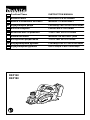
Cordless Planer INSTRUCTION MANUAL
SI
Brezžini obli NAVODILO ZA UPORABO
AL
Makina e zdrukthimit me bateri MANUALI I PËRDORIMIT
BG
HR
Bežina blanjalica PRIRUNIK S UPUTAMA
MK
RO
Rindea fr cablu MANUAL DE INSTRUCIUNI
RS
RUS
UA
DKP140
DKP180

2
1
2
3
1 011755
1
2 011389
1
2
3 011737
1
2
4 011738
1
2
3
5 011739
1
2
4
3
6 011740
1
2
3
4
5
7 002555
1
2
3
4
5
6
7
8
9
8 002556
1
2
4
3
9 011740
1
2
3
4
5
6
7
8
9
10
10 002565
1
2
3
4
5
6
7
11 002566
1
2
12 011741
1
13 007802
14 011757
1
2
15 011758

3
1
2
16 011759
17 002580
1
2
18 011752
1
2
19 011760 20 011761
21 010183
22 003634
23 011748
1
24 002588
1
2
3
4
5
25 002589 26 002590
1
27 001145
1
2
28 011749
1
2
29 011753
1
2
30 011750

4
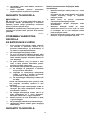
ENGLISH (Original instructions)
Explanation of general view
1-1. Button
1-2. Red indicator
1-3. Battery cartridge
2-1. Star mark
3-1. Pointer
3-2. Knob
4-1. Lock-off lever
4-2. Switch trigger
5-1. Planer blade
5-2. Rear base
5-3. Foot
6-1. Socket wrench
6-2. Bolt
6-3. Loosen
6-4. Tighten
7-1. Bolts
7-2. Drum
7-3. Planer blade
7-4. Drum cover
7-5. Adjusting plate
8-1. Inside edge of gauge plate
8-2. Blade edge
8-3. Planer blade
8-4. Adjusting plate
8-5. Screws
8-6. Heel
8-7. Back side of gauge base
8-8. Gauge plate
8-9. Gauge base
9-1. Socket wrench
9-2. Bolt
9-3. Loosen
9-4. Tighten
10-1. Pan head screw
10-2. Adjusting plate
10-3. Planer blade locating lugs
10-4. Gauge plate
10-5. Heel of adjusting plate
10-6. Set plate
10-7. Inside flank of gauge plate
10-8. Gauge base
10-9. Back side of gauge base
10-10. Mini planer blade
11-1. Mini planer blade
11-2. Groove
11-3. Set plate
11-4. Hex. flange head bolts
11-5. Drum cover
11-6. Drum
11-7. Adjusting plate
12-1. Nozzle
12-2. Dust bag
13-1. Fastener
15-1. Elbow
15-2. Nozzle
16-1. Start
16-2. End
18-1. Blade edge
18-2. Cutting line
19-1. Screw
19-2. Edge fence (optional accessory)
24-1. Sharpening holder
25-1. Wing nut
25-2. Blade (A)
25-3. Blade (B)
25-4. Side (D)
25-5. Side (C)
27-1. Limit mark
28-1. Chip cover
28-2. Screwdriver
29-1. Nozzle
29-2. Screwdriver
30-1. Brush holder cap
30-2. Screwdriver
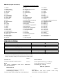
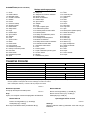
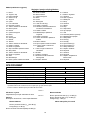
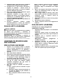
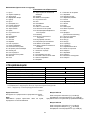
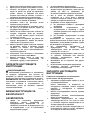
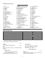
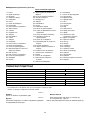
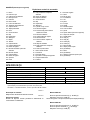
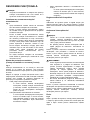
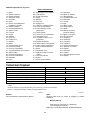
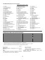
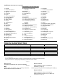
SPECIFICATIONS
Model DKP140 DKP180
Planing width 82 mm
Planing depth 1.6 mm 2 mm
Shiplapping depth 9 mm
No load speed (min
-1
) 15,000
Overall length 329 mm 333 mm
Net weight 3.3 kg 3.4 kg
Rated voltage D.C. 14.4 V D.C. 18 V
• Due to our continuing program of research and development, the specifications herein are subject to change without notice.
• Specifications and battery cartridge may differ from country to country.
• Weight, with battery cartridge, according to EPTA-Procedure 01/2003
ENE001-1
Intended use
The tool is intended for planing wood.
ENG905-1
Noise
The typical A-weighted noise level determined
according to EN60745:
Model DKP140
Sound pressure level (L
pA
) : 80 dB (A)
Uncertainty (K) : 3 dB (A)
The noise level under working may exceed 80 dB (A).
Model DKP180
Sound pressure level (L
pA
) : 84 dB (A)
Sound power level (L
WA
) : 95 dB (A)
Uncertainty (K) : 3 dB (A)
Wear ear protection
ENG900-1
Vibration
The vibration total value (tri-axial vector sum)
determined according to EN60745:

5
Model DKP140
Work mode : planing softwood
Vibration emission (a
h
) : 3.5 m/s
2
Uncertainty (K) : 1.5 m/s
2
Model DKP180
Work mode : planing softwood
Vibration emission (a
h
) : 4.5 m/s
2
Uncertainty (K) : 1.5 m/s
2
ENG901-1
•
The declared vibration emission value has been
measured in accordance with the standard test method
and may be used for comparing one tool with another.
• The declared vibration emission value may also be
used in a preliminary assessment of exposure.
WARNING:
•
The vibration emission during actual use of the power
tool can differ from the declared emission value
depending on the ways in which the tool is used.
• Be sure to identify safety measures to protect the
operator that are based on an estimation of
exposure in the actual conditions of use (taking
account of all parts of the operating cycle such as
the times when the tool is switched off and when it
is running idle in addition to the trigger time).
ENH101-16
For European countries only
EC Declaration of Conformity
We Makita Corporation as the responsible manufacturer
declare that the following Makita machine(s):
Designation of Machine:
Cordless Planer
Model No./ Type: DKP140, DKP180
are of series production and
Conforms to the following European Directives:
2006/42/EC
And are manufactured in accordance with the following
standards or standardised documents:
EN60745
The technical documentation is kept by:
Makita International Europe Ltd.
Tech ni cal Depa rt me nt,
Michigan Drive, Tongwell,
Milton Keynes, Bucks MK15 8JD, England
06.06.2013
000230
Tomo ya su Kat o
Director
Makita Corporation
3-11-8, Sumiyoshi-cho,
Anjo, Aichi, 446-8502, JAPAN
GEA010-1
General Power Tool Safety
Warnings
WARNING Read all safety warnings and all
instructions. Failure to follow the warnings and
instructions may result in electric shock, fire and/or
serious injury.
Save all warnings and instructions for
future reference.
GEB064-2
CORDLESS PLANER SAFETY
WARNINGS
1. Wait for the cutter to stop before setting the
tool down. An exposed rotating cutter may
engage the surface leading to possible loss of
control and serious injury.
2. Use clamps or another practical way to secure
and support the workpiece to a stable
platform. Holding the work by your hand or
against the body leaves it unstable and may lead
to loss of control.
3. Rags, cloth, cord, string and the like should
never be left around the work area.
4. Avoid cutting nails. Inspect for and remove all
nails from the workpiece before operation.
5. Use only sharp blades. Handle the blades very
carefully.
6. Be sure the blade installation bolts are
securely tightened before operation.
7. Hold the tool firmly with both hands.
8. Keep hands away from rotating parts.
9. Before using the tool on an actual workpiece,
let it run for a while. Watch for vibration or
wobbling that could indicate poor installation
or a poorly balanced blade.
10. Make sure the blade is not contacting the
workpiece before the switch is turned on.
11.
Wait until the blade attains full speed before cutting.
12. Always switch off and wait for the blades to
come to a complete stop before any adjusting.
13. Never stick your finger into the chip chute.
Chute may jam when cutting damp wood.
Clean out chips with a stick.
14. Do not leave the tool running. Operate the tool
only when hand-held.
15. Always change both blades or covers on the
drum, otherwise the resulting imbalance will
cause vibration and shorten tool life.
16.
Use only Makita blades specified in this manual.
17.
Always use the correct dust mask/respirator for
the material and application you are working with.
SAVE THESE INSTRUCTIONS.

6
WARNING:
DO NOT let comfort or familiarity with product
(gained from repeated use) replace strict adherence
to safety rules for the subject product.
MISUSE or failure to follow the safety rules stated in this
instruction manual may cause serious personal injury.
ENC007-8
IMPORTANT SAFETY
INSTRUCTIONS
FOR BATTERY CARTRIDGE
1.
Before using battery cartridge, read all instructions
and cautionary markings on (1) battery charger, (2)
battery, and (3) product using battery.
2. Do not disassemble battery cartridge.
3. If operating time has become excessively
shorter, stop operating immediately. It may
result in a risk of overheating, possible burns
and even an explosion.
4.
If electrolyte gets into your eyes, rinse them out
with clear water and seek medical attention right
away. It may result in loss of your eyesight.
5. Do not short the battery cartridge:
(1) Do not touch the terminals with any
conductive material.
(2) Avoid storing battery cartridge in a
container with other metal objects such
as nails, coins, etc.
(3) Do not expose battery cartridge to water
or rain.
A battery short can cause a large current flow,
overheating, possible burns and even a breakdown.
6. Do not store the tool and battery cartridge in
locations where the temperature may reach or
exceed 50 C (122 F).
7. Do not incinerate the battery cartridge even if
it is severely damaged or is completely worn
out. The battery cartridge can explode in a fire.
8. Be careful not to drop or strike battery.
9. Do not use a damaged battery.
10. Follow your local regulations relating to
disposal of battery.
SAVE THESE INSTRUCTIONS.
Tips for maintaining maximum battery life
1. Charge the battery cartridge before
completely discharged.
Always stop tool operation and charge the battery
cartridge when you notice less tool power.
2.
Never recharge a fully charged battery cartridge.
Overcharging shortens the battery service life.
3.
Charge the battery cartridge with room temperature
at 10
C - 40
C (50
F - 104
F). Let a hot battery
cartridge cool down before charging it.
4.
Charge the battery cartridge once in every six
months if you do not use it for a long period of time.
FUNCTIONAL DESCRIPTION
CAUTION:
• Always be sure that the tool is switched off and the
battery cartridge is removed before adjusting or
checking function on the tool.
Installing or removing battery cartridge
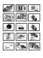
Fig.1
• Always switch off the tool before installing or
removing of the battery cartridge.
•
To r emove the battery cartridge , slide it from the too l
while sliding the button on the front of the cartridge.
•
To i ns ta ll the batte ry cart ridge, align t he t ong ue on th e
battery cartridge with the groove in the housing and
slip it into place. Always insert it all the way until it
locks in place with a little click. If you can see the red
indicator on the upper side of the button, it is not
locked completely. Install it fully until the red indicator
cannot be seen. If not, it may accidentally fall out of
the tool, causing injury to you or someone around you.
• Do not use force when installing the battery
cartridge. If the cartridge does not slide in easily, it
is not being inserted correctly.
Battery protection system
(Battery cartridge with a star mark)
Fig.2
The battery cartridge with a star mark is equipped with
the protection system, which automatically cuts off the
output power for its long service life.
The tool stops during operation when the tool and/or
battery are placed under the following situation. This is
caused by the activation of protection system and does
not show the tool trouble.
• When the tool is overloaded:
At this time, release the switch trigger,
remove the battery cartridge and remove
causes of overload and then pull the switch
trigger again to restart.
• When battery cells get hot:
If any operation of the switch trigger, the
motor will remain stopped. At this time, stop
use of the tool and cool or charge the battery
cartridge after removing it from the tool.
• When the remaining battery capacity gets low:
If any operation of the switch trigger, the
motor will remain stopped. At this time,
remove the battery cartridge from the tool
and charge it .
Adjusting depth of cut
Fig.3
Depth of cut may be adjusted by simply turning the knob
on the front of the tool so that the pointer points the
desired depth of cut.

7
Switch action
Fig.4
CAUTION:
• Before installing the battery cartridge into the tool,
always check to see that the switch trigger
actuates properly and returns to the "OFF"
position when released.
• Do not pull the switch trigger hard without pressing
the lock-off lever. This can cause switch breakage.
To pr even t the swi tc h tr ig ger from bein g acc id en ta ll y
pulled, a lock-off lever is provided. To start the tool, slide
the lock-off lever and pull the switch trigger. Release the
switch trigger to stop.
WARNING:
• For your safety, this tool is equipped with lock-off
lever which prevents the tool from unintended
starting. NEVER use the tool if it runs when you
simply pull the switch trigger without pressing the
lock-off lever. Return tool a MAKITA service center
for proper repairs BEFORE further usage.
• NEVER tape down or defeat purpose and function
of lock-off lever.
To pr even t the swi tc h tr ig ger from bein g acc id en ta ll y
pulled, a lock-off button is provided.
To st art th e to ol, d epress th e lo ck-of f bu tton and p ul l t he
switch trigger. Release the switch trigger to stop.
Foot
Fig.5
After a cutting operation, raise the back side of the tool
and a foot comes under the level of the rear base. This
prevents the tool blades to be damaged.
ASSEMBLY
CAUTION:
• Always be sure that the tool is switched off and the
battery cartridge is removed before carrying out
any work on the tool.
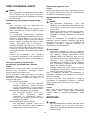
Removing or installing planer blades
CAUTION:
• Tighten the blade installation bolts carefully when
attaching the blades to the tool. A loose installation
bolt can be dangerous. Always check to see they
are tightened securely.
• Handle the blades very carefully. Use gloves or
rags to protect your fingers or hands when
removing or installing the blades.
• Use only the Makita wrench provided to remove or
install the blades. Failure to do so may result in
overtightening or insufficient tightening of the
installation bolts. This could cause an injury.
For tool with conventional planer blades
Fig.6
Fig.7
Fig.8
To remove the blades on the drum, unscrew the
installation bolts with the socket wrench. The drum
cover comes off together with the blades.
To i nsta ll t he blad es , fi rst c le an o ut al l chi ps o r fo re ign m at ter
adhering to the drum or blades. Use blades of the same
dimensions and weight, or drum oscillation/vibration will result,
causing poor planing action and, eventually, tool breakdown.
Place the blade on the gauge base so that the blade edge is
perfectly flush with the inside edge of the gauge plate. Place
the adjusting plate on the blade, then simply press in the
heel of the adjusting plate flush with the back side of the
gauge base and tighten two screws on the adjusting plate.
Now slip the heel of the adjusting plate into the drum groove,
then fit the drum cover on it. Tighten all the installation bolts
evenly and alternately with the socket wrench.
Repeat the above procedures for the other blade.
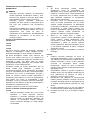
For tool with mini planer blades
Fig.9
1.
Remove the existing blade, if the tool has been in use,
carefully clean the drum surfaces and the drum cover.
To re move th e blade s on the dr um, un sc re w the t hree
installation bolts with the socket wrench. The drum
cover comes off together with the blades.
Fig.10
2. To install the blades, loosely attach the adjusting
plate to the set plate with the pan head screws
and set the mini planer blade on the gauge base
so that the cutting edge of the blade is perfectly
flush with the inside flank of the gauge plate.
3.
Set the adjusting plate/set plate on the gauge base
so that the planer blade locating lugs on the set plate
rest in the mini planer blade groove, then press in the
heel of the adjusting plate flush with the back side of
the gauge base and tighten the pan head screws.
4. It is important that the blade sits flush with the inside
flank of the gauge plate, the planer blade locating
lugs sit in the blade groove and the heel of the
adjusting plate is flush with the back side of the
gauge base. Check this alignment carefully to ensure
uniform cutting.
5. Slip the heel of the adjusting plate into the groove
of the drum.
Fig.11
6. Set the drum cover over the adjusting plate/set
plate and screw in the three hex flange head bolts
so that a gap exists between the drum and the
set plate to slide the mini planer blade into
position. The blade will be positioned by the
planer blade locating lugs on the set plate.
7. The blade's lengthwise adjustment will need to be
manually positioned so that the blade ends are

8
clear and equidistant from the housing on one
side and the metal bracket on the other.
8.
Tighten the three hex flange head bolts (with the socket
wrench provided) and rotate the drum to check
clearances between the blade ends and the tool body.
9. Check the three hex flange head bolts for final
tightness.
10. Repeat procedures 1 - 9 for the other blade.
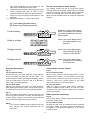
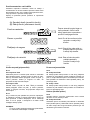
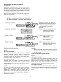
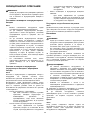
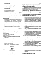
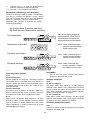
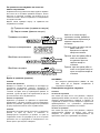
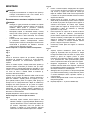
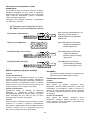
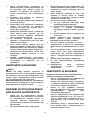
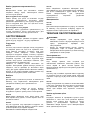
For the correct planer blade setting
Your planing surface will end up rough and uneven,
unless the blade is set properly and securely. The blade
must be mounted so that the cutting edge is absolutely
level, that is, parallel to the surface of the rear base.
Refer to some examples below for proper and improper
settings.
(A)
(B)
(B)
(A)
(B)
(A)
(A) Front base (Movable shoe)
(B) Rear base (Stationary shoe)
Correct setting
Nicks in surface
Gouging at start
Gouging at end
Although this side view cannot
show it, the edges of the blades
run perfectly parallel to the rear
base surface.
Cause: One or both blades fails to
have edge parallel to rear
base line.
Cause: One or both blade edges
fails to protrude enough in
relation to rear base line.
Cause: One or both blade edges
protrudes too far in relation
to rear base line.
EN0004-1
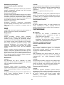
Dust bag (accessory)
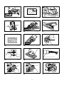
Fig.12
For tool without nozzle
Remove the chip cover and install the nozzle (optional
accessory). Attach the dust bag onto the nozzle . The
nozzle is tapered. When attaching the dust bag, push it
onto the nozzle firmly as far as it will go to prevent it
from coming off during operation.
For tool with nozzle
Attach the dust bag onto the nozzle. The nozzle is tapered.
When attaching the dust bag, push it onto the nozzle firmly as
far as it will go to prevent it from coming off during operation.
Fig.13
When the dust bag is about half full, remove the dust bag from
the tool and pull the fastener out. Empty the dust bag of its
contents, tapping it lightly so as to remove particles adhering
to the insides which might hamper further collection.
NOTE:
• If you connect a Makita vacuum cleaner to this tool,
more efficient and cleaner operations can be
performed.
Connecting a vacuum cleaner
Fig.14
For tool without nozzle
When you wish to perform clean planing operation, connect
a Makita vacuum cleaner to your tool. Before connecting the
vacuum cleaner, remove the chip cover from the tool. Then
connect a hose of the vacuum cleaner to the nozzle
(optional accessory) as shown in the figures.
For tool with nozzle
When you wish to perform clean planing operation,
connect a Makita vacuum cleaner to your tool. Then
connect a hose of the vacuum cleaner to the nozzle as
shown in the figures.
Elbow (optional accessory)
Fig.15
Use of elbow allows change of chip discharge direction
to perform cleaner work.
For tool without nozzle
Remove the chip cover and install the nozzle (optional
accessory). Attach the elbow (optional accessory) on
the nozzle of the tool by just slipping on it. To remove
it, just pull it out.

9
For tool with nozzle
Attach the elbow (optional accessory) on the nozzle of
the tool by just slipping on it. To re mo ve it, jus t pul l it ou t.
OPERATION
Hold the tool firmly with one hand on the knob and the other
hand on the switch handle when performing the tool.
Planing operation
Fig.16
First, rest the tool front base flat upon the workpiece surface
without the blades making any contact. Switch on and wait
until the blades attain full speed. Then move the tool gently
forward. Apply pressure on the front of tool at the start of
planing, and at the back at the end of planing. Planing will
be easier if you incline the workpiece in stationary fashion,
so that you can plane somewhat downhill.
The speed and depth of cut determine the kind of finish.
The power planer keeps cutting at a speed that will not
result in jamming by chips. For rough cutting, the depth
of cut can be increased, while for a good finish you
should reduce the depth of cut and advance the tool
more slowly.
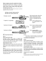
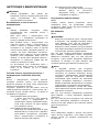
Shiplapping (Rabbeting)
Fig.17
To ma ke a s te pped cut as shown i n th e fi gu re, u se th e
edge fence (guide rule) which is obtained as accessory.
Fig.18
Draw a cutting line on the workpiece. Insert the edge
fence into the hole in the front of the tool. Align the
blade edge with the cutting line.
Fig.19
Adjust the edge fence until it comes in contact with the
side of the workpiece, then secure it by tightening the
screw.
Fig.20
When planing, move the tool with the edge fence flush
with the side of the workpiece. Otherwise uneven
planing may result.
Maximum shiplapping (rabbeting) depth is 9 mm.
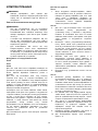
Fig.21
You may wish to add to the length of the fence by
attaching an extra piece of wood. Convenient holes are
provided in the fence for this purpose, and also for
attaching an extension guide (optional accessory).
Chamfering
Fig.22
Fig.23
To m ak e a cham fe ring c ut a s s ho wn i n the figure , al ig n
the "V" groove in the front base with the edge of the
workpiece and plane it.
MAINTENANCE
CAUTION:
• Always be sure that the tool is switched off and the
battery cartridge is removed before attempting to
perform inspection or maintenance.
• Never use gasoline, benzine, thinner, alcohol or
the like. Discoloration, deformation or cracks may
result.
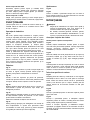
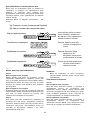
Sharpening the planer blades
For conventional blades only
Fig.24
Always keep your blades sharp for the best
performance possible. Use the sharpening holder
(optional accessory) to remove nicks and produce a fine
edge.
Fig.25
First, loosen the two wing nuts on the holder and insert
the blades (A) and (B), so that they contact the sides
(C) and (D). Then tighten the wing nuts.
Fig.26
Immerse the dressing stone in water for 2 or 3 minutes
before sharpening. Hold the holder so that the both
blades contact the dressing stone for simultaneous
sharpening at the same angle.
Replacing carbon brushes
Fig.27
Remove and check the carbon brushes regularly.
Replace when they wear down to the limit mark. Keep
the carbon brushes clean and free to slip in the holders.
Both carbon brushes should be replaced at the same
time. Use only identical carbon brushes.
Fig.28
Fig.29
Use a screwdriver to remove the chip cover or nozzle.
Fig.30
Use a screwdriver to remove the brush holder caps.
Take out t he wo rn c ar bon br us hes, ins er t t he n ew o ne s
and secure the brush holder caps.
To maint ain produ ct S AFETY an d RE LIABI LI TY, re pair s,
any other maintenance or adjustment should be
performed by Makita Authorized Service Centers,
always using Makita replacement parts.

10
OPTIONAL ACCESSORIES
CAUTION:
• These accessories or attachments are
recommended for use with your Makita tool
specified in this manual. The use of any other
accessories or attachments might present a risk of
injury to persons. Only use accessory or
attachment for its stated purpose.
If you need any assistance for more details regarding
these accessories, ask your local Makita Service Center.
• High-speed steel Planer blade
• Tungsten-carbide Planer blade (For longer blade
life)
• Mini planer blade
• Sharpening holder assembly
• Blade gauge
• Set plate set
• Edge fence (Guide rule)
• Extension guide set
• Dressing stone
• Nozzle
• Dust bag assembly
• Elbow
• Socket wrench
• Plastic carrying case
• Various type of Makita genuine batteries and
chargers
NOTE:
• Some items in the list may be included in the tool
package as standard accessories. They may differ
from country to country.

11
SLOVENŠINA (izvirna navodila)
Razlaga splošnega pogleda
1-1. Gumb
1-2. Rdei indikator
1-3. Baterijski vložek
2-1. Oznaka z zvezdico
3-1. Kazalec
3-2. Roica
4-1. Roica za zaklep
4-2. Sprožilno stikalo
5-1. Rezilo oblia
5-2. Zadnji drsnik
5-3. Noga
6-1. Nasadni klju
6-2. Vijak z matico
6-3. Zrahljati
6-4. Priviti
7-1. Vijaki z matico
7-2. Boben
7-3. Rezilo oblia
7-4. Pokrov bobna
7-5. Nastavitvena ploša
8-1. Notranji rob merilne ploše
8-2. Rob rezila
8-3. Rezilo oblia
8-4. Nastavitvena ploša
8-5. Vijaki
8-6. Zadnji rob
8-7. Zadnja stran merila za nastavitev
8-8. Merilna ploša
8-9. Merilo za nastavitev
9-1. Nasadni klju
9-2. Vijak z matico
9-3. Zrahljati
9-4. Priviti
10-1. Vijak z valjasto glavo
10-2. Nastavitvena ploša
10-3. Pritrdilni jeziki za rezilo oblia
10-4. Merilna ploša
10-5. Zadnji rob nastavitvene ploše
10-6. Fiksna ploša
10-7. Notranji bok merilne ploše
10-8. Merilo za nastavitev
10-9. Zadnja stran merila za nastavitev
10-10. Miniaturna rezila oblia
11-1. Miniaturna rezila oblia
11-2. Utor
11-3. Fiksna ploša
11-4. Vijaki s šestrobno prirobno glavo
11-5. Pokrov bobna
11-6. Boben
11-7. Nastavitvena ploša
12-1. Šoba
12-2. Vreka za prah
13-1. Pritrjevalnik
15-1. Koleno
15-2. Šoba
16-1. Zagon
16-2. Konec
18-1. Rob rezila
18-2. Linija reza
19-1. Vijak
19-2. Robni prislon (dodatni pribor)
24-1. Držalo za brušenje
25-1. Krilna matica
25-2. Rezilo (A)
25-3. Rezilo (B)
25-4. Stranica (D)
25-5. Stranica (C)
27-1. Meja obrabljenosti
28-1. Šitnik za odrezke
28-2. Izvija
29-1. Šoba
29-2. Izvija
30-1. Pokrov krtake
30-2. Izvija
TEHNINI PODATKI
Model DKP140 DKP180
Širina oblanja 82 mm
Globina oblanja 1,6 mm 2 mm
Globina ladijskega poda 9 mm
Hitrost brez obremenitve (min
-1
) 15.000
Celotna dolžina 329 mm 333 mm
Neto teža 3,3 kg 3,4 kg
Nazivna napetost D.C. 14,4 V D.C. 18 V
• Zaradi našega nenehnega programa raziskav in razvoja si pridržujemo pravico do spremembe tehninih podatkov brez obvestila.
• Tehnini podatki in baterijski vložki se lahko razlikujejo od države do države.
• Teža z baterijskim vložkom je v skladu z EPTA-postopkom 01/2003
ENE001-1
Namenska uporaba
Orodje je namenjeno za oblanje lesa.
ENG905-1
Hrup
Tipini, z A ocenjeni vrednosti hrupa glede na EN60745:
Model DKP140
Raven zvonega tlaka (L
pA
): 80 dB (A)
Odstopanje (K): 3 dB (A)
Nivo hrupa med delom lahko preseže 80 dB (A).
Model DKP180
Raven zvonega tlaka (L
pA
): 84 dB (A)
Raven zvone moi (L
WA
): 95 dB (A)
Odstopanje (K): 3 dB (A)
Uporabljajte zašito za sluh
ENG900-1
Vibracije
Skupne vrednosti vibracij (vektorska vsota treh osi) po
EN60745:

12
Model DKP140
Delovni nain : oblanje mehkega lesa
Oddajanje tresljajev (a
h
): 3,5 m/s
2
Odstopanje (K): 1,5 m/s
2
Model DKP180
Delovni nain : oblanje mehkega lesa
Oddajanje tresljajev (a
h
): 4,5 m/s
2
Odstopanje (K): 1,5 m/s
2
ENG901-1
•
Navedena vrednost oddajanja vibracij je bila
izmerjena v skladu s standardnimi metodami
testiranja in se lahko uporablja za primerjavo orodij.
• Navedena vrednost oddajanja vibracij se lahko
uporablja tudi pri predhodni oceni izpostavljenosti.
OPOZORILO:
•
Oddajanje vibracij med dejansko uporabo elektrinega
orodja se lahko razlikuje od navedene vrednosti
oddajanja, odvisno od naina uporabe orodja.
•
Upravljavec mora za lastno zašito poznati varnostne
ukrepe, ki temeljijo na oceni izpostavljenosti v
dejanskih pogojih uporabe (upoštevajo celoten
delovni proces v trenutkih, ko je orodje izkljueno in ko
deluje v prostem teku z dodatkom asa sprožitve).
ENH101-16
Samo za evropske države
ES Izjava o skladnosti
Makita Corporation kot odgovorni proizvajalec
izjavlja, da je naslednji stroj Makita:
Oznaka stroja:
Brezžini obli
Št. modela / tip: DKP140, DKP180
del serijske proizvodnje in
Je skladen z naslednjimi evropskimi direktivami:
2006/42/ES
In je izdelan v skladu z naslednjimi standardi ali
standardiziranimi dokumenti:
EN60745
Tehn ino dokumentacijo hrani:
Makita International Europe Ltd.
Tehn ini oddelek,
Michigan Drive, Tongwell,
Milton Keynes, Bucks MK15 8JD, England
06.06.2013
000230
Tomo ya su Kat o
Direktor
Makita Corporation
3-11-8, Sumiyoshi-cho,
Anjo, Aichi, 446-8502, JAPAN
GEA010-1
Splošna varnostna opozorila za
elektrino orodje
OPOZORILO Preberite vsa varnostna opozorila
in navodila. Neupoštevanje opozoril in navodil lahko
vodi do elektrinega udara, požara, in/ali hudih telesnih
poškodb.
Shranite vsa opozorila in navodila za
kasnejšo uporabo.
GEB064-2
VARNOSTNA OPOZORILA ZA
BREZŽINI OBLI
1. Preden odložite orodje, poakajte, da se
rezalnik ustavi. Izpostavljeni vrtei se rezalnik se
lahko zatakne v površini, kar lahko povzroi
morebitno izgubo nadzora in hude telesne
poškodbe.
2. Uporabljajte sponke ali druge praktine
naine za pritrditev in podporo obdelovanca
na stabilno podlago. e držite obdelovanca z
roko ali ga naslanjate na telo, je nestabilen in
lahko povzroi izgubo nadzora.
3. Krpe, kabel, vrvice in podobno je treba vedno
odstraniti iz delovnega obmoja.
4. Izogibajte se rezanju žebljev. Pred delom
poišite in odstranite vse žeblje iz
obdelovanca.
5. Uporabljajte samo ostra rezila. Z rezili ravnajte
zelo previdno.
6. Pred delom se prepriajte, ali so vijaki za
pritrditev rezila trdno pritrjeni.
7. Orodje trdno držite z obema rokama.
8. Ne približujte rok vrteim se delom.
9. Orodje naj nekaj asa deluje, preden ga
uporabite na dejanskem obdelovancu. Pazite
na tresljaje ali majanje, ki bi lahko nakazovali
slabo namestitev ali slabo uravnoteženo rezilo.
10. Preden vklopite stikalo, se prepriajte, ali se
rezilo ne dotika obdelovanca.
11. Pred rezanjem poakajte, da rezilo doseže
polno hitrost.
12. Pred vsako prilagoditvijo orodje vedno
izkljuite in poakajte, da se rezila popolnoma
ustavijo.
13. Nikoli ne vtikajte prstov v žleb za ostružke.
Med rezanjem vlažnega lesa se lahko žleb
zamaši. Ostružke oistite s palico.
14. Orodja ne pustite delovati brez nadzora.
Dovoljeno ga je uporabljati samo rono.
15. Vedno zamenjajte obe rezili ali pokrova na
bobnu. V nasprotnem primeru bo posledina
neuravnoteženost povzroila vibriranje in
skrajšala življenjsko dobo orodja.

13
16. Uporabljajte samo rezila Makita, doloena v
tem prironiku.
17. Vedno uporabite pravilno protiprašno
masko/respirator za material in uporabo.
SHRANITE TA NAVODILA.
OPOZORILO:
NE dopustite si, da bi zaradi udobnejšega dela ali
poznavanja izdelka (pridobljenega z vekratno
uporabo) opustili strogo upoštevanje varnostnih
pravil pri pravilni uporabi stroja.
ZLORABA ali neupoštevanje varnostnih pravil v teh
navodilih za uporabo lahko povzroi hude telesne
poškodbe.
ENC007-8
POMEMBNA VARNOSTNA
NAVODILA
ZA BATERIJSKE VLOŽKE
1. Pred uporabo baterijskega vložka preberite
vsa navodila in opozorilne oznake na (1)
polnilniku akumulatorja, (2) akumulatorju in
(3) izdelku, ki uporablja akumulator.
2. Ne razstavljajte baterijskega vložka.
3. e se je as delovanja obutno skrajšal, takoj
prekinite z uporabo. V nasprotnem primeru je
lahko rezultat pregretje, morebitne opekline in
celo eksplozija.
4. e pride elektrolit v oi, jih sperite s isto
vodo in takoj poišite zdravniško pomo.
Posledica je lahko izguba vida.
5.
Ne povzroite kratkega stika baterijskega vložka:
(1) Ne dotikajte se prikljukov s kakršnim
koli prevodnim materialom.
(2) Izogibajte se shranjevanju baterijskega
vložka v posodo z drugimi kovinskimi
predmeti kot so žeblji, kovanci itn.
(3) Ne izpostavljajte baterijskega vložka vodi
ali dežju.
Kratek stik akumulatorja lahko povzroi velik
tok, pregretje, morebitne opekline in celo
eksplozijo.
6. Ne shranjujte orodja in baterijskega vložka na
lokacijah, kjer lahko temperatura doseže ali
preseže 50 C (122 F).
7. Ne sežigajte baterijskega vložka, tudi e je
hudo poškodovan ali v celoti izpraznjen.
Baterijski vložek lahko v ognju eksplodira.
8. Bodite previdni, da vam akumulator ne pade
in ga ne udarjajte.
9. Ne uporabljajte poškodovanih akumulatorjev.
10. Upoštevajte lokalne uredbe glede odlaganja
akumulatorja.
SHRANITE TA NAVODILA.
Nasveti za maksimalno življenjsko dobo
akumulatorja
1. Napolnite baterijski vložek preden se v celoti
izprazni.
Ko opazite, da ima orodje manjšo mo, vedno
ustavite delovanje orodja in napolnite
baterijski vložek.
2. Nikoli znova ne polnite popolnoma
napolnjenega baterijskega vložka.
Prenapolnjenje skrajša življenjsko dobo
akumulatorja.
3. Napolnite baterijski vložek pri sobni
temperaturi med 10 C in 40 C (50 F - 104
F). Poakajte, da se vro baterijski vložek
pred polnjenjem ohladi.
4. Napolnite baterijski vložek enkrat vsakih šest
mesecev, e ga ne uporabljate dlje asa.

14
OPIS DELOVANJA
POZOR:
• Pred vsako nastavitvijo ali pregledom delovanja
orodja se prepriajte, da je le to izkljueno in da je
akumulatorska baterija odstranjena.
Namešanje ali odstranjevanje
akumulatorske baterije
Sl.1
• Vedno izklopite orodje, preden namestite ali
odstranite akumulatorsko baterijo.
• Za odstranitev akumulatorske baterije iz orodja jo
premaknite iz orodja, ob tem pa premaknite gumb
na sprednji strani akumulatorske baterije.
• Za namešanje baterije poravnajte jeziek na
akumulatorski bateriji z utorom v ohišju in potisnite
akumulatorsko baterijo v ležiše. Akumulatorsko
baterijo vstavite do konca, da se razlono zaskoi.
e vidite rdeo rto na zgornji strani gumba, ta ni
popolnoma zaklenjen. Popolnoma namestite, tako
da rdea rta ni vidna. e tega ne upoštevate,
lahko baterija nepriakovano izpade iz orodja in
poškoduje vas ali osebe v neposredni bližini.
• Akumulatorske baterije ne namešajte na silo. e
akumulatorska baterija zlahka ne zdrsne noter, ni
ustrezno vstavljena.
Sistem za zašito akumulatorja
(akumulatorska baterija z oznako z zvezdico)
Sl.2
Akumulatorska baterija z oznako z zvezdico je
opremljena z zašitnim sistemom, ki samodejno prekine
napajanje za daljšo življenjsko dobo.
e se orodje in/ali akumulator znajde v naslednji
situaciji, orodje prekine z obratovanjem. To povzroi
vklop zašitnega sistema in ne pomeni napake orodja.
• Kadar je orodje preobremenjeno:
Sedaj spustite sprožilno stikalo, odstranite
akumulatorsko baterijo in odpravite vzrok za
preobremenitev, nato pa znova povlecite
sprožilno stikalo za ponovni zagon.
• Kadar se celice akumulatorja segrejejo:
e uporabite sprožilno stikalo, bo motor ostal
ugasnjen. V tem trenutku prenehajte
uporabljati orodje in ohladite ali napolnite
akumulatorsko baterijo, potem ko ste jo
odstranili iz orodja.
• Kadar je akumulator skoraj izpraznjen:
e uporabite sprožilno stikalo, bo motor ostal
ugasnjen. V tem primeru odstranite
akumulatorsko baterijo iz orodja in jo
napolnite.
Nastavljanje globine rezanja
Sl.3
Globino reza lahko nastavite tako, da enostavno
obrnete gumb na sprednjem delu orodja, tako da
kazalec kaže želeno globino reza.
Delovanje stikala
Sl.4
POZOR:
• Preden namestite akumulatorsko baterijo v orodje
se vedno prepriajte, da je stikalo brezhibno in da
se vraa v položaj za izklop (OFF), ko ga spustite.
• Ne vlecite sprožilnega stikala mono, ne da bi pri
tem pritisnili roico za zaklep. To lahko povzroi
zlom stikala.
Za prepreevanje nenamernega vklopa sprožilnega
stikala je namešena roica za zaklep. Za zagon orodja
hkrati premaknite roico za zaklep in povlecite sprožilno
stikalo. Za izklop orodja spustite sprožilno stikalo.
OPOZORILO:
• Za vašo varnost je to orodje opremljeno z roico
za zaklep, ki prepreuje nenamerni zagon orodja.
NIKOLI ne uporabljajte orodja, kadar zane
delovati, e povleete samo sprožilno stikalo in pri
tem ne pritisnete roice za zaklep. PRED nadaljnjo
uporabo vrnite orodje v servisni center MAKITA v
ustrezno popravilo.
• NIKOLI ne zalepite in ne izniite namena in
funkcije roice za zaklep.
Za zašito pred nehotenim vklopom je stikalo
opremljeno s sprostilnim gumbom.
Za zagon orodja hkrati pritisnite na sprostilni gumb in
sprožilno stikalo. Za izklop orodja spustite sprožilno
stikalo.
Noga
Sl.5
Po rezanju dvignite zadnjo stran orodja. Noga se nahaja
pod nivojem zadnje osnovne ploše. S tem boste
prepreili poškodbe rezil orodja.
MONTAŽA
POZOR:
• Pred vsako izvedbo dela na orodju se prepriajte,
da je le to izkljueno in da je akumulatorska
baterija odstranjena.
Odstranjevanje ali namešanje rezil oblia
POZOR:
• Ko pritrjujete rezila na orodje, previdno privijte
vijake za namestitev rezila. Ohlapna namestitev
vijakov je lahko nevarna. Vedno preverite, ali so
dovolj trdno priviti.

15
• Z rezili ravnajte zelo previdno. Uporabljajte
rokavice ali krpo za zašito prstov ali rok pri
odstranjevanju ali namešanju rezil.
• Za odstranjevanje ali namestitev rezila uporabite
samo priloženi klju Makita. V nasprotnem primeru
je lahko posledica ezmerno ali nezadostno
privitje montažnih vijakov. To lahko povzroi
poškodbe.
Za orodje s konvencionalnimi rezili oblia
Sl.6
Sl.7
Sl.8
Za odstranjevanje rezil na bobnu odvijte montažne
vijake z nasadnim kljuem. Pokrov bobna se sname
skupaj z rezili.
Za namestitev rezil najprej oistite vse odrezke in tujke
z bobna ali rezil. Uporabite rezila z istimi merami in težo.
V nasprotnem primeru bo prišlo do oscilacije/vibriranja
bobna, zaradi esar se bo zmanjšala zmogljivost
oblanja in možne bodo poškodbe orodja.
Položite rezilo na osnovno plošo z merilom tako, da je
rob rezila prislonjen na notranji rob ploše z merilom.
Položite nastavitveno plošo na rezilo, nato pa pritisnite
zadnji rob proti osnovni ploši z merilom do te mere, da
se zadnji rob poravnano zakljui z merilom za
nastavitev ter zategnite vijaka na nastavitveni ploši.
Vstavite zadnji rob nastavitvene ploše v utor bobna in
namestite pokrov bobna. Vse montažne vijake
enakomerno izmenino zategnite z nasadnim kljuem.
Ponovite zgornji postopek za drugo rezilo.
Za orodje z miniaturnimi rezili oblia
Sl.9
1. Odstranite obstojee rezilo. e ste orodje
uporabljali, skrbno oistite površine bobna in
pokrov bobna. Za odstranjevanje rezil na bobnu
odvijte tri montažne vijake z nasadnim kljuem.
Pokrov bobna se sname skupaj z rezili.
Sl.10
2. Za namestitev rezil ohlapno prikljuite
nastavitveno plošo na fiksno plošo z vijaki z
valjasto glavo in nastavite miniaturno rezilo oblia
na osnovno plošo z merilom, tako da je rezalni
rob rezila popolnoma poravnan z notranjim robom
ploše z merilom.
3. Nastavite nastavitveno plošo/fiksno plošo na
osnovni ploši z merilom, tako da so pritrdilni
jeziki za rezilo oblia na fiksni ploši nameš
eni
v utor miniaturnega rezila oblia, nato pa pritisnite
zadnji rob nastavitvene ploše do te mere, da se
zadnji rob poravna z osnovno plošo z merilom,
in zategnite vijake z valjasto glavo.
4. Pomembno je, da je rezilo poravnano z notranjim
robom ploše z merilom, da se pritrdilni jeziki za
rezilo oblia prilegajo v utor rezila in da je zadnji
rob nastavitvene ploše poravnan z zadnjim
robom osnovne ploše z merilom. Skrbno
preverite to poravnanost, da zagotovite
enakomerno rezanje.
5. Pomaknite zadnji rob nastavitvene ploše v utor
bobna.
Sl.11
6. Namestite pokrov bobna ez nastavitveno
plošo/fiksno plošo in privijte tri vijake s
šestrobno prirobno glavo, tako da ostane reža
med bobnom in fiksno plošo, kamor boste
potisnili miniaturno rezilo oblia. S pritrdilnimi
jeziki za rezilo oblia boste pritrdili rezilo na
fiksno plošo.
7. Po dolžini boste morali rono nastaviti rezilo, tako
da sta konca rezila jasno in enakomerno
oddaljena od ohišja na eni strani in kovinskega
okvirja na drugi strani.
8. Privijte tri vijake s šestrobno prirobno glavo (s
priloženim nasadnim kljuem) in zavrtite boben,
da preverite razdalje med koncema rezila in
ohišjem orodja.
9. Preverite konno zategnjenost treh vijakov s
šestrobno prirobno glavo.
10. Ponovite korake od 1 do 9 za drugo rezilo.

16
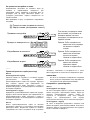
Pravilna nastavitev rezil oblia
Posledice nepravilne nastavitve nožev se kažejo v
neenakomerni in neravni obdelavi površine. Rezilo mora
biti namešeno tako, da je rezalni rob popolnoma raven,
torej vzporeden s površino zadnje pete.
Spodaj so prikazani primeri pravilnih in nepravilnih
nastavitev.
(A)
(B)
(B)
(A)
(B)
(A)
(A) Sprednji drsnik (premični drsnik)
(B) Zadnji drsnik (stacionarni drsnik)
Pravilna nastavitev
Zareze v površini
Žlebljenje ob zagonu
Žlebljenje ob ustavitvi
Čeprav stranski pogled tega ne
more pokazati, robovi rezila
tečejo popolnoma vzporedno s
površino zadnjega drsnika.
Vzrok: Eno ali oba rezila ne tečeta
vzporedno z zadnjo linijo
drsnika.
Vzrok: Eden ali oba roba rezila ne
prebijata zadosti v povezavi
z zadnjo linijo drsnika.
Vzrok: Eden ali oba roba rezila
prebijata predaleč v
povezavi z zadnjo linijo
drsnika.
EN0004-1
Vreka za prah (pripomoek)
Sl.12
Za orodje brez šobe
Odstranite pokrov za zašito pred odrezki in namestite
šobo (dodatni pribor). Pritrdite vreko za prah na šobo.
Šoba je koniasta. Kadar pritrjujete vreko za prah, jo
mono potisnite, kolikor je mogoe na šobo, da
prepreite snetje med delovanjem.
Za orodje s šobo
Pritrdite vreko za prah na šobo. Šoba je koniasta.
Kadar pritrjujete vreko za prah, jo mono potisnite,
kolikor je mogoe na šobo, da prepreite snetje med
delovanjem.
Sl.13
Ko je vreka za prah približno do polovice napolnjena,
jo odstranite z orodja in izvlecite pritrjevalnik. Vreko za
prah izpraznite z rahlim udarjanjem, da se odstranijo
delci, ki so se sprijeli v notranjosti in bi lahko ovirali
nadaljnje zbiranje prahu.
OPOMBA:
• e na to orodje prikljuite sesalnik za prah Makita,
bo vaše delo uinkovitejše in istejše.
Povezovanje sesalnika
Sl.14
Za orodje brez šobe
Za istejši potek oblanja lahko na vaš stroj prikljuite
sesalnik za prah Makita. Preden prikljuite sesalnik na
prah, z orodja odstranite pokrov za zašito pred odrezki.
Nato povežite cev sesalnika s šobo (dodatni pribor), kot
prikazujejo slike.
Za orodje s šobo
Za istejši potek oblanja lahko na vaš stroj prikljuite
sesalnik za prah Makita. Nato povežite cev sesalnika s
šobo, kot prikazujejo slike.
Koleno (dodatni pribor)
Sl.15
Uporaba kolena omogoa spremembo smeri izmeta
odrezkov za ve istoe pri delu.
Za orodje brez šobe
Odstranite pokrov za zašito pred odrezki in namestite
šobo (dodatni pribor). Namestite koleno (dodatni pribor)
na šobo orodja, tako da ga enostavno potisnete gor. Za
odstranitev ga enostavno izvlecite.

17
Za orodje s šobo
Namestite koleno (dodatni pribor) na šobo orodja, tako
da ga enostavno potisnete gor. Za odstranitev ga
enostavno izvlecite.
DELOVANJE
Pri uporabi trdno držite orodje z eno roko za gumb in z
drugo za preklopni roaj.
Oblanje
Sl.16
Najprej postavite sprednjo skobeljno peto plosko na
obdelovanca, tako da se skobeljna noža niesar ne
dotikata. Vklopite orodje in poakajte, da dosežejo rezila
polno število vrtljajev. Nato obli poasi pomikajte
naprej. Ob zaetku obdelovanca pritiskajte na sprednjo
skobeljno peto, ob koncu obdelovanca pa na zadnjo
skobeljno peto. Za lažji potek oblanja lahko
obdelovanec nagnete in, medtem ko ga trdno držite,
oblate navzdol.
Potek obdelave je odvisen od hitrosti in od globine reza.
Obli deluje z optimalno hitrostjo, ki prepreuje zastoj
odrezkov. Za grobe reze lahko nastavite vejo globino
odvzema. e želite dosei visoko kakovost obdelave,
morate nekoliko zmanjšati globino odvzema in hitrost
pomika.
Utori za ladijski pod (izdelava utorov)
Sl.17
Za izdelavo stopenjskega reza, kot je prikazano na sliki,
uporabite robni prislon (vodilno ravnilo), ki je na voljo kot
pribor.
Sl.18
Na obdelovanca narišite linijo reza. Vstavite robni
prislon v odprtino na sprednji strani orodja. Poravnajte
rob rezila z linijo reza.
Sl.19
Prilagajajte robni prislon, dokler se ne dotakne strani
obdelovanca, nato pa ga pritrdite s privijanjem vijaka.
Sl.20
Med oblanjem premikajte orodje z robnim prislonom
poravnano s stranico obdelovanca. Sicer lahko pride do
neravnega oblanja.
Najveja globina utora za ladijski pod (izdelave utorov)
je 9 mm.
Sl.21
Prislon lahko podaljšate, tako da pritrdite dodatni kos
lesa. Za ta namen in za pritrditev vodila podaljška
(dodatni pribor) so v prislonu izdelane prirone odprtine.
Posnemanje robov
Sl.22
Sl.23
Za posnemanje robov v skladu s sliko poravnajte
„V“ utor sprednje skobeljne pete z robom obdelovanca
in ga oblajte.
VZDRŽEVANJE
POZOR:
• Preden se lotite pregledovanja ali vzdrževanja
orodja, se vedno prepriajte, da je orodje
izklopljeno in akumulatorska baterija odstranjena.
• Nikoli ne uporabljajte bencina, razredila, alkohola
ali podobnega. V tem primeru se orodje lahko
razbarva, deformira, lahko pa tudi nastanejo
razpoke.
Brušenje rezil oblia
Samo za obiajna rezila
Sl.24
Za ohranitev visoke zmogljivosti je treba rezila redno
brusiti. Uporabite držalo za ostrenje (dodatni pribor), da
odstranite zareze in dobite fini rob.
Sl.25
Najprej popustite obe krilni matici na držalu rezil in
vstavite rezili (A) in (B), tako da sta prislonjeni k robu
(C) in robu (D). Nato zategnite krilni matici.
Sl.26
Pred zaetkom brušenja namakajte brusni kamen v vodi
2-3 minute. Držalo rezil vodite tako, da sta obe rezili v
stiku z brusilnim kamnom. Tako lahko obe rezili
nabrusite istoasno in pod enakim kotom.
Menjava oglenih krtak
Sl.27
Ogleni krtaki odstranjujte in preverjajte redno. Ko sta
obrabljeni do meje obrabljenosti, ju zamenjajte. Ogleni
krtaki morata biti isti, da bosta lahko neovirano
zdrsnili v držali. Zamenjajte obe ogleni krtaki naenkrat.
Uporabljajte le enaki ogleni krtaki.
Sl.28
Sl.29
Z izvijaem odstranite pokrov za zašito pred odrezki ali
šobo.
Sl.30
Z izvijaem odstranite pokrova krtak. Izvlecite izrabljeni
ogleni krtaki, namestite novi in privijte oba pokrova
krtak.
VARNO in ZANESLJIVO delovanje tega izdelka bo
zagotovljeno le, e boste popravila, vzdrževanje in
nastavitve prepustili pooblašenemu servisu za orodja
Makita, ki vgrajuje izkljuno originalne nadomestne dele.

18
DODATNI PRIBOR
POZOR:
• Ta dod at ni prib or ali prip om oki so predvideni za
uporabo z orodjem Makita, ki je opisano v teh
navodilih za uporabo. Pri uporabi drugega pribora
ali pripomokov obstaja nevarnost telesnih
poškodb. Dodatni pribor ali pripomoke
uporabljajte samo za navedeni namen.
Za ve informacij o dodatnem priboru in opremi se
obrnite na najbližji pooblašeni Makita servis.
• Jekleno rezilo za visoko število vrtljajev
• Rezilo oblia iz karbidne trdine (za daljšo
življenjsko dobo rezila)
• Miniaturna rezila oblia
• Sklop za brušenje rezil
• Merilo rezila
• Komplet fiksne ploše
• Robni prislon (vodilno ravnilo)
• Garnitura vodil za podaljšanje
• Brusni kamen
• Šoba
• Sklop vreke za prah
• Koleno
• Nasadni klju
• Plastien kovek za prenašanje
• Razline originalne Makita akumulatorske baterije
in polnilniki
OPOMBA:
• Nekateri predmeti na seznamu so lahko priloženi
orodju kot standardni pribor. Lahko se razlikuje od
države do države.

19
SHQIP (Udhëzimet origjinale)
Shpjegim i pamjes së përgjithshme
1-1. Butoni
1-2. Treguesi i kuq
1-3. Kutia e baterisë
2-1. Shënim me yll
3-1. Treguesi
3-2. Çelësi
4-1. Leva e bllokimit
4-2. Këmbëza e çelësit
5-1. Thika e makinës së zdrukthimit
5-2. Baza e pasme
5-3. Këmba
6-1. Çelësi hekzagonal
6-2. Buloni
6-3. Liruesi
6-4. Shtrënguesi
7-1. Bulonat
7-2. Tamburi
7-3. Thika e makinës së zdrukthimit
7-4. Kapaku i tamburit
7-5. Pllaka e rregullimit
8-1.
Skaji i brendshëm i pllakës së matësit
8-2. Skaji i fletës
8-3. Thika e makinës së zdrukthimit
8-4. Pllaka e rregullimit
8-5. Vidat
8-6. Mbështetësja
8-7. Pjesa e pasme e bazës së matësit
8-8. Pllaka e matësit
8-9. Baza e matësit
9-1. Çelësi hekzagonal
9-2. Buloni
9-3. Liruesi
9-4. Shtrënguesi
10-1. Vidë me kokë kryq
10-2. Pllaka e rregullimit
10-3. Kanalet e pozicionimit të thikave
të makinës së zdrukthimit
10-4. Pllaka e matësit
10-5. Mbështetësja e pllakës së
rregullimit
10-6. Pllaka e vendosjes
10-7. Krahu i brendshëm i pllakës së
matësit
10-8. Baza e matësit
10-9.
Pjesa e pasme e bazës së matësit
10-10.
Thika e vogël e makinës së
zdrukthimit
11-1. Thika e vogël e makinës së
zdrukthimit
11-2. Brazda
11-3. Pllaka e vendosjes
11-4. Bulonat me kokë të fllanxhës
hekzagonale
11-5. Kapaku i tamburit
11-6. Tamburi
11-7. Pllaka e rregullimit
12-1. Hundëza
12-2. Qese e pluhurit
13-1. Mbërthyesi
15-1. Bërryl
15-2. Hundëza
16-1. Ndezja
16-2. Fikja
18-1. Skaji i fletës
18-2. Vija e prerjes
19-1. Vida
19-2. Kufizuesi (aksesor opsional)
24-1. Mbajtësja për mprehjen
25-1. Dadoja flutur
25-2. Fleta (A)
25-3. Fleta (B)
25-4. Pjesa anësore (D)
25-5. Pjesa anësore (C)
27-1. Shenja kufizuese
28-1. Kapaku i ashklave
28-2. Kaçavida
29-1. Hundëza
29-2. Kaçavida
30-1. Kapaku i mbajtëses së
karboncinave
30-2. Kaçavida
SPECIFIKIMET
Modeli DKP140 DKP180
Gjerësia e zdrukthimit 82 mm
Thellësia e zdrukthimit 1,6 mm 2 mm
Thellësia e kanalit të dërrasës 9 mm
Shpejtësia pa ngarkesë (min
-1
) 15 000
Gjatësia e përgjithshme 329 mm 333 mm
Pesha neto 3,3 kg 3,4 kg
Tensioni n omin al DC 1 4,4 V DC 1 8 V
• Për shkak të programit tonë të vazhdueshëm të kërkim-zhvillimit, specifikimet e përmendura këtu mund të ndryshojnë pa njoftim paraprak.
• Specifikimet dhe kutia e baterisë mund të ndryshojnë nga njëri shtet në tjetrin.
• Pesha me kutinë e baterisë sipas procedurës EPTA 01.2003
ENE001-1
Përdorimi i synuar
Vegla është synuar për zdrukthim të drurit.
ENG905-1
Zhurma
Niveli tipik i zhurmës A, i matur sipas EN60745:
Modeli DKP140
Niveli i presionit të zërit (L
pA
): 80 dB (A)
Pasiguria (K): 3 dB (A)
Niveli i zhurmës mund të tejkalojë 80 dB (A).
Modeli DKP180
Niveli i presionit të zërit (L
pA
): 84 dB (A)
Niveli i fuqisë së zërit (L
WA
): 95 dB (A)
Pasiguria (K): 3 dB (A)
Mbani mbrojtëse për veshët

20
ENG900-1
Dridhjet
Vlera totale e dridhjeve (shuma e vektorit me tre akse)
përcaktohet sipas EN60745:
Modeli DKP140
Regjimi i punës : zdrukthimi i drurëve të butë
Emetimi i dridhjeve (a
h
): 3,5 m/s
2
Pasiguria (K): 1,5 m/s
2
Modeli DKP180
Regjimi i punës : zdrukthimi i drurëve të butë
Emetimi i dridhjeve (a
h
): 4,5 m/s
2
Pasiguria (K): 1,5 m/s
2
ENG901-1
•
Vlera e deklaruar e emetimeve të dridhjeve është
matur sipas metodës standarde të testimit dhe mund
të përdoret për të krahasuar një vegël me një tjetër.
•
Vlera e deklaruar e emetimeve të dridhjeve mund të
përdoret për një vlerësim paraprak të ekspozimit.
PARALAJMËRIM:
•
Emetimet e dridhjeve gjatë përdorimit aktual të veglës
elektrike mund të ndryshojnë nga vlerat e deklaruara të
emetimeve në varësi të mënyrave sesi përdoret vegla.
• Sigurohuni që të identifikoni masat e sigurisë për
mbrojtjen e përdoruesit, që bazohen në vlerësimin
e ekspozimit ndaj kushteve aktuale të përdorimit
(duke marrë parasysh të gjitha pjesët e ciklit të
funksionimit si ato kur vegla është e fikur dhe
punon pa prerë, ashtu edhe kohën e përdorimit).
ENH101-16
Vetëm për shtetet evropiane
Deklarata e konformitetit me KE-në
Ne, Makita Corporation, si prodhuesi përgjegjës
deklarojmë që makineria(të) e mëposhtme Makita:
Emërtimi i makinerisë:
Makina e zdrukthimit me bateri
Nr. i modelit/ Lloji: DKP140, DKP180
janë të prodhimit në seri dhe
Pajtohet me direktivën evropiane të mëposhtme:
2006/42/KE
Dhe janë prodhuar në përputhje me standardet e
mëposhtme ose me dokumentet e standardizuara:
EN60745
Dokumentacioni teknik ruhet nga:
Makita International Europe Ltd.
Tech ni cal Depa rt me nt,
Michigan Drive, Tongwell,
Milton Keynes, Bucks MK15 8JD, England
06.06.2013
000230
Tomo ya su Kat o
Director
Makita Corporation
3-11-8, Sumiyoshi-cho,
Anjo, Aichi, 446-8502, JAPAN
GEA010-1
Paralajmërimet e përgjithshme
për sigurinë e veglës
PARALAJMËRIM Lexoni të gjitha paralajmërimet
dhe udhëzimet për sigurinë. Mosndjekja e
paralajmërimeve dhe udhëzimeve mund të rezultojë në
goditje elektrike, zjarr dhe/ose dëmtim serioz.
Ruajini të gjitha paralajmërimet dhe
udhëzimet për të ardhmen.
GEB064-2
PARALAJMËRIME SIGURIE PËR
MAKINËN E ZDRUKTHIMIT ME
BATERI
1. Prisni që prerësi të ndalojë përpara se ta
vendosni veglën poshtë. Prerësi i ekspozuar
mund të aktivizojë sipërfaqen dhe të shkaktojë
humbje të kontrollit dhe lëndim të rëndë.
2. Përdorni morseta ose ndonjë mënyrë tjetër
praktike për ta siguruar dhe për ta mbështetur
materialin e punës në një platformë të
qëndrueshme. Mbajtja e materialit me dorë ose
përkundrejt trupit tuaj e lë atë të paqëndrueshëm
dhe mund të shkaktojë humbje të kontrollit.
3. Leckat, rrobat, kordoni, fijet dhe objekte të
ngjashme nuk duhen lënë asnjëherë në zonën
e punës.
4. Shmangni prerjen e gozhdëve. Kontrolloni për
gozhdë dhe hiqini të gjitha nga materiali i
punës përpara përdorimit.
5. Përdorni vetëm fletë të mprehta. Mbajini fletët
me shumë kujdes.
6. Sigurohuni që bulonat e vendosjes së fletës të
jenë të shtrënguar fort përpara përdorimit.
7. Mbajeni veglën fort me të dyja duart.
8. Mbajini duart larg pjesëve rrotulluese.
9. Përpara se të përdorni veglën mbi një material
të vërtetë, lëreni të punojë për pak kohë.
Shikoni për dridhje ose lëkundje që mund të
tregojnë instalim të gabuar ose disk të
pabalancuar mirë.
10. Sigurohuni që disku nuk e prek materialin e
punës përpara se të ndizet çelësi.
11. Prisni derisa fleta të arrijë shpejtësi të plotë
përpara se të bëni prerje.
Pagina se încarcă ...
Pagina se încarcă ...
Pagina se încarcă ...
Pagina se încarcă ...
Pagina se încarcă ...
Pagina se încarcă ...
Pagina se încarcă ...
Pagina se încarcă ...
Pagina se încarcă ...
Pagina se încarcă ...
Pagina se încarcă ...
Pagina se încarcă ...
Pagina se încarcă ...
Pagina se încarcă ...
Pagina se încarcă ...
Pagina se încarcă ...
Pagina se încarcă ...
Pagina se încarcă ...
Pagina se încarcă ...
Pagina se încarcă ...
Pagina se încarcă ...
Pagina se încarcă ...
Pagina se încarcă ...
Pagina se încarcă ...
Pagina se încarcă ...
Pagina se încarcă ...
Pagina se încarcă ...
Pagina se încarcă ...
Pagina se încarcă ...
Pagina se încarcă ...
Pagina se încarcă ...
Pagina se încarcă ...
Pagina se încarcă ...
Pagina se încarcă ...
Pagina se încarcă ...
Pagina se încarcă ...
Pagina se încarcă ...
Pagina se încarcă ...
Pagina se încarcă ...
Pagina se încarcă ...
Pagina se încarcă ...
Pagina se încarcă ...
Pagina se încarcă ...
Pagina se încarcă ...
Pagina se încarcă ...
Pagina se încarcă ...
Pagina se încarcă ...
Pagina se încarcă ...
Pagina se încarcă ...
Pagina se încarcă ...
Pagina se încarcă ...
Pagina se încarcă ...
Pagina se încarcă ...
Pagina se încarcă ...
Pagina se încarcă ...
Pagina se încarcă ...
Pagina se încarcă ...
Pagina se încarcă ...
Pagina se încarcă ...
Pagina se încarcă ...
Pagina se încarcă ...
Pagina se încarcă ...
Pagina se încarcă ...
Pagina se încarcă ...
-
 1
1
-
 2
2
-
 3
3
-
 4
4
-
 5
5
-
 6
6
-
 7
7
-
 8
8
-
 9
9
-
 10
10
-
 11
11
-
 12
12
-
 13
13
-
 14
14
-
 15
15
-
 16
16
-
 17
17
-
 18
18
-
 19
19
-
 20
20
-
 21
21
-
 22
22
-
 23
23
-
 24
24
-
 25
25
-
 26
26
-
 27
27
-
 28
28
-
 29
29
-
 30
30
-
 31
31
-
 32
32
-
 33
33
-
 34
34
-
 35
35
-
 36
36
-
 37
37
-
 38
38
-
 39
39
-
 40
40
-
 41
41
-
 42
42
-
 43
43
-
 44
44
-
 45
45
-
 46
46
-
 47
47
-
 48
48
-
 49
49
-
 50
50
-
 51
51
-
 52
52
-
 53
53
-
 54
54
-
 55
55
-
 56
56
-
 57
57
-
 58
58
-
 59
59
-
 60
60
-
 61
61
-
 62
62
-
 63
63
-
 64
64
-
 65
65
-
 66
66
-
 67
67
-
 68
68
-
 69
69
-
 70
70
-
 71
71
-
 72
72
-
 73
73
-
 74
74
-
 75
75
-
 76
76
-
 77
77
-
 78
78
-
 79
79
-
 80
80
-
 81
81
-
 82
82
-
 83
83
-
 84
84


Makita DKP140 Manual de utilizare
- Categorie
- Unelte electrice
- Tip
- Manual de utilizare
- Acest manual este potrivit și pentru
Lucrări conexe
-
Makita KP0800 Manual de utilizare
-
Makita DKP181 Manual de utilizare
-
Makita DJS200 Manual de utilizare
-
-
Makita UB100D Manual de utilizare
-
-
Makita SD100D Manual de utilizare
-
Makita VC008G Manual de utilizare
-
-
Makita M1902 Manual de utilizare
Alte documente
-
Maktec MT191 Manual de utilizare
-
Dolmar AT3723U Manualul proprietarului
-
Maktec MT431 Manual de utilizare
-
-
Ryobi EPN-6082 Manual de utilizare
-
Parkside PEH 30 A1 ELECTRIC PLANER Operation and Safety Notes
-
Tryton THG900 Manual de utilizare
-
-
Hitachi P18DSL Handling Instructions Manual
-
Panasonic ERGS60 Instrucțiuni de utilizare