Dolmar AT3723U Manualul proprietarului
- Categorie
- Unelte electrice
- Tip
- Manualul proprietarului

1
GB
Cordless Grass Trimmer INSTRUCTION MANUAL
UA
Акумуляторна газонокосарка ІНСТРУКЦІЯ З ЕКСПЛУАТАЦІЇ
PL
Akumulatorowa wykaszarka do trawy
INSTRUKCJA OBSŁUGI
RO
Motocositoare pentru iarbă fără cablu
MANUAL DE INSTRUCŢIUNI
DE
Akku-Rasentrimmer BEDIENUNGSANLEITUNG
HU
Vezeték nélküli fűkasza HASZNÁLATI KÉZIKÖNYV
SK
Akumulátorová kosačka NÁVOD NA OBSLUHU
CZ
Akumulátorový vyžínač NÁVOD K OBSLUZE
AT-3723 U

2
1
2
3
1 015386
2
1
2 015387
1
3 015587
1
2
4 015573
1
2
5 015589
1
6 015588
1
7 015602
1
2
3
8 015574
2
1
9 015575
10 015623
1
2
11 015577
12 015604
2
3
1
13 015578

3
16 015581
1
2
3
4
17 015620
1
2
3
4
18 015621
1
19 015399
20 015582
1
2
21 015583
1
22 015622
23 013822
1
24 013823
25 013824
26 013825 27 013826
28 013827
1
2
3
15 015580
3
4
5
2
6
1
14 015579

4
29 015450

5
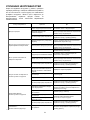
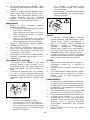
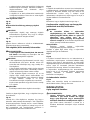
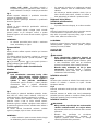
ENGLISH (Original instructions)
Explanation of general view
1-1. Red indicator
1-2. Button
1-3. Battery cartridge
2-1. Battery indicator
2-2. Check button
3-1. Main power button
4-1. Lock-off lever
4-2. Switch trigger
5-1. Main power button
5-2. Speed indicator
6-1. Reverse button
7-1. Most effective cutting area
8-1. Grip
8-2. Handle
8-3. Screw
9-1. Handle clamp
9-2. Screw
11-1. Clamp
11-2. Bolt
13-1. Cutter
13-2. Clamp
13-3. Bolt
14-1. Hex wrench
14-2. Nut
14-3. Cup
14-4. Clamp washer
14-5. Metal blade
14-6. Receive washer
15-1. Hex wrench
15-2. Box driver
15-3. Tighten
17-1. Nylon cutting head
17-2. Metal guard
17-3. Receive washer
17-4. Hex wrench
18-1. Plastic blade
18-2. Nut
18-3. Receive washer
18-4. Hex wrench
19-1. Hex wrench
21-1. Buckle
21-2. Hook
22-1. Buckle
24-1. 80 - 100 mm
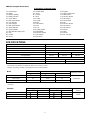
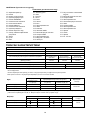
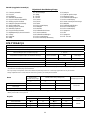
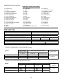
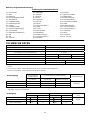
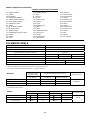
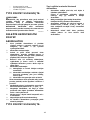
SPECIFICATIONS
Model AT-3723 U
Type of handle Bike handle
No load speed 3,500 / 5,300 / 6,500 min
-1
Overall length (without cutting tool) 1,754 mm
Applicable cutting tool (country specific) Metal blade Nylon cutting head Plastic blade
Cutting diameter 230 mm 350 mm 255 mm
Rated voltage D.C. 36 V
Standard battery cartridge AP-1815 / AP-1820 AP-183 / AP-1840 / AP-1850
Net weight (with metal blade) 4.7 kg 5.2 kg
• Due to our continuing program of research and development, the specifications herein are subject to change without notice.
• Specifications and battery cartridge may differ from country to country.
• Weight, with battery cartridge, according to EPTA-Procedure 01/2003
Noise
Sound pressure level average
Sound power level average
L
PA
(dB (A)) L
WA
(dB (A))
Uncertainty K (dB (A))
Applicable standard
Metal blade 75 86 0.4
Plastic blade 83 92.8 0.6
Nylon cutting head 77 90 2.2
2000/14/EC
• Even if the sound pressure level listed above is 80 dB (A) or less, the level under working may exceed 80 dB (A). Wear ear
protection.
Vibration Left hand Right hand
a
h
(m/s
2
)
Uncertainty K (m/s
2
)
a
h
(m/s
2
)
Uncertainty K (m/s
2
)
Applicable
standard
Metal blade 2.5 1.5 2.5 1.5
Plastic blade 2.5 1.5 2.5 1.5
Nylon cutting head 2.5 1.5 2.5 1.5
EN786

6
ENG901-1
•
The declared vibration emission value has been
measured in accordance with the standard test
method and may be used for comparing one tool
with another.
• The declared vibration emission value may also be
used in a preliminary assessment of exposure.
WARNING:
• The vibration emission during actual use of the
power tool can differ from the declared emission
value depending on the ways in which the tool is
used.
• Be sure to identify safety measures to protect the
operator that are based on an estimation of
exposure in the actual conditions of use (taking
account of all parts of the operating cycle such as
the times when the tool is switched off and when it
is running idle in addition to the trigger time).
END119-1
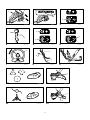
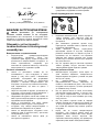
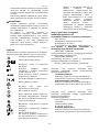
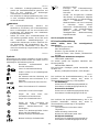
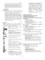
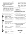
Symbols
The following show the symbols used for the equipment.
Be sure that you understand their meaning before use.
・ Take particular care and attention.
・ Read instruction manual.
・ Danger; be aware of thrown objects.
・ The distance between the tool and
bystanders must be at least 15 m.
・ Keep bystanders away.
・ Keep distance at least 15 m.
・ Avoid kickback.
・ Wear a helmet, goggles and ear
protection.
・ Wear protective gloves.
・ Wear sturdy boots with nonslip soles.
Steeltoed safety boots are
recommended.
・ Do not expose to moisture.
・ Top permissible tool speed.
・ Top permissible tool speed.
・ Only for EU countries
Do not dispose of electric equipment or
battery pack together with household
waste material!
In observance of the European
Directives, on Waste Electric and
Electronic Equipment and Batteries and
Accumulators and Waste Batteries and
Accumulators and their implementation
in accordance with national laws,
electric equipment and batteries and
battery pack(s) that have reached the
end of their life must be collected
separately and returned to an
environmentally compatible recycling
facility.
ENH114-1
For European countries only
EC Declaration of Conformity
Makita declares that the following Machine(s):
Designation of Machine:
Cordless Grass Trimmer
Model No./ Type: AT-3723 U
Specifications: see "SPECIFICATIONS" table.
Conforms to the following European Directives:
2000/14/EC, 2006/42/EC
They are manufactured in accordance with the following
standard or standardized documents:
EN/ISO11806, EN60335
The technical file in accordance with 2006/42/EC is
available from:
Makita, Jan-Baptist Vinkstraat 2, 3070, Belgium
ENH115-1
The conformity assessment procedure required by
Directive 2000/14/EC was in Accordance with annex V.
With metal blade
Measured sound power level 86 dB (A)
Guaranteed sound power level 86 dB (A)
Plastic blade
Measured sound power level 92.8 dB (A)
Guaranteed sound power level 93 dB (A)
ENH115-1
The conformity assessment procedure required by
Directive 2000/14/EC was in Accordance with annex VI.
Notified Body:
TÜV Rheinland LGA Products GmbH
Tillystraße 2
90431 Nürnberg, Germany
Identification number 0197
With nylon cutting head
Measured sound power level 90 dB (A)
Guaranteed sound power level 92 dB (A)
16.1.2015
000331
Yasushi Fukaya
Director
Makita, Jan-Baptist Vinkstraat 2, 3070, Belgium
15m(50FT)
Cd
Ni-MH
Li-ion

7
GEB068-6
IMPORTANT SAFETY
INSTRUCTIONS
WARNING! Read all safety warnings and all
instructions. Failure to follow the warnings and
instructions may result in electric shock, fire and/or
serious injury.
Save all warnings and
instructions for future reference.
Intended use
1. The cordless grass trimmer / brushcutter / string
trimmer is only intended for cutting grass, weeds,
bushes and undergrowth. It should not be used
for any other purpose such as edging or hedge
cutting as this may cause injury.
General instructions
1. Never allow people unfamiliar with these
instructions, people (including children) with
reduced physical, sensory or mental capabilities,
or lack of experience and knowledge to use the
tool. Children should be supervised to ensure that
they do not play with the tool.
2. Before starting the tool, read this instruction
manual to become familiar with the handling of
the tool.
3. Do not lend the tool to a person with insufficient
experience or knowledge regarding handling of
brushcutters and string trimmers.
4. When lending the tool, always attach this
instruction manual.
5. Handle the tool with the utmost care and attention.
6. Never use the tool after consuming alcohol or
drugs, or if feeling tired or ill.
7. Never attempt to modify the tool.
8. Follow the regulations about handling of
brushcutters and string trimmers in your country.
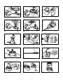
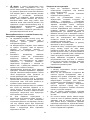
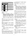
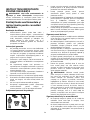
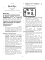
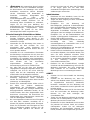
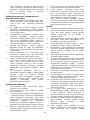
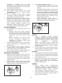
Personal protective equipment
013122
1. Wear safety helmet, protective goggles and
protective gloves to protect yourself from flying
debris or falling objects.
2. Wear ear protection such as ear muffs to prevent
hearing loss.
3. Wear proper clothing and shoes for safe
operation, such as a work overall and sturdy, non-
slip shoes. Do not wear loose clothing or jewelry.
Loose clothes, jewelry or long hair can be caught
in moving parts.
4. When touching the cutting blade, wear protective
gloves. Cutting blades can cut bare hands
severely.
Work area safety
1. Operate the tool under good visibility and daylight
conditions only. Do not operate the tool in
darkness or fog.
2. Do not operate the tool in explosive atmospheres,
such as in the presence of flammable liquids,
gases or dust. The tool creates sparks which may
ignite the dust or fumes.
3. During operation, never stand on an unstable or
slippery surface or a steep slope. During the cold
season, beware of ice and snow and always
ensure secure footing.
4. During operation, keep bystanders or animals at
least 15 m away from the tool. Stop the tool as
soon as someone approaches.
5. Before operation, examine the work area for
stones or other solid objects. They can be thrown
or cause dangerous kickback and result in
serious injury and/or property damage.
6.
WARNING: Use of this product can create
dust containing chemicals which may cause
respiratory or other illnesses. Some examples of
these chemicals are compounds found in
pesticides, insecticides, fertilizers and herbicides.
Your risk from these exposures varies, depending
on how often you do this type of work. To reduce
your exposure to these chemicals: work in a well
ventilated area, and work with approved safety
equipment, such as those dust masks that are
specially designed to filter out microscopic
particles.
Electrical and battery safety
1. Do not expose the tool to rain or wet conditions.
Water entering the tool will increase the risk of
electric shock.
2. Do not use the tool if the switch does not turn it
on and off. Any tool that cannot be controlled with
the switch is dangerous and must be repaired.
3. Prevent unintentional starting. Ensure the switch
is in the off-position before installing a battery
pack, picking up or carrying the tool. Carrying the
tool with your finger on the switch or energising
the tool that have the switch on invites accidents.
4. Recharge only with the charger specified by the
manufacturer. A charger that is suitable for one
type of battery pack may create a risk of fire when
used with another battery pack.
5. Use the tool only with specifically designated
battery packs. Use of any other battery packs
may create a risk of injury and fire.

8
6. When battery pack is not in use, keep it away
from other metal objects, like paper clips, coins,
keys, nails, screws or other small metal objects,
that can make a connection from one terminal to
another. Shorting the battery terminals together
may cause burns or a fire.
7. Under abusive conditions, liquid may be ejected
from the battery; avoid contact. If contact
accidentally occurs, flush with water. If liquid
contacts eyes, seek medical help. Liquid ejected
from the battery may cause irritation or burns.
Putting into operation
1. Before assembling or adjusting the tool, remove
the battery cartridge.
2. Before handling the cutter blade, wear protective
gloves.
3. Before installing the battery cartridge, inspect the
tool for damages, loose screws/nuts or improper
assembly. Sharpen blunt cutter blade. If the cutter
blade is bent or damaged, replace it. Check all
control levers and switches for easy action. Clean
and dry the handles.
4. Never attempt to switch on the tool if it is
damaged or not fully assembled. Otherwise
serious injury may result.
5. Adjust the shoulder harness and hand grip to suit
the operator's body size.
6. When inserting a battery cartridge, keep the
cutting attachment clear of your body and other
object, including the ground. It may rotate when
starting and may cause injury or damage to the
tool and/or property.
7. Remove any adjusting key, wrench or blade cover
before turning the tool on. An accessory left
attached to a rotating part of the tool may result in
personal injury.
OPERATION
1. In the event of an emergency, switch off the tool
immediately.
2. If you feel any unusual condition (e.g. noise,
vibration) during operation, switch off the tool. Do
not use the tool until the cause is recognized and
solved.
3. The cutting attachment continues to rotate for a
short period after turning the tool off. Don't rush to
contact the cutting attachment.
4. During operation, use the shoulder harness. Keep
the tool on your right side firmly.
5. Do not overreach. Keep proper footing and
balance at all times. Watch for hidden obstacles
such as tree stumps, roots and ditches to avoid
stumbling.
6. Never work on a ladder or tree to avoid loss of
control.
7. If the tool gets heavy impact or fall, check the
condition before continuing work. Check the
controls and safety devices for malfunction. If
there is any damage or doubt, ask our authorized
service center for the inspection and repair.
8. Do not touch the gear case. The gear case
becomes hot during operation.
9. Take a rest to prevent loss of control caused by
fatigue. We recommend taking a 10 to 20-minute
rest every hour.
10. When you leave the tool, even if it is a short time,
always remove the battery cartridge. The
unattended tool with the battery cartridge installed
may be used by unauthorized person and cause
serious accident.
11. If grass or branches get caught between the
cutting attachment and guard, always turn the
tool off and remove the battery cartridge before
cleaning. Otherwise the cutting attachment may
rotate unintentionally and cause serious injury.
12. If the cutting attachment hits stones or other hard
objects, immediately turn the tool off. Then
remove the battery cartridge and inspect the
cutting attachment.
13. Check the cutting attachment frequently during
operation for cracks or damages. Before the
inspection, remove the battery cartridge and wait
until the cutting attachment stops completely.
Replace damaged cutting attachment
immediately, even if it has only superficial cracks.
14. Never cut above waist height.
15. Before starting the cutting operation, wait until the
cutting attachment reaches a constant speed
after turning the tool on.
16. When using metal blades, swing the tool evenly
in half-circle from right to left, like using a scythe.
17. Hold the tool by insulated gripping surfaces only,
because the cutter blade may contact hidden
wiring. Cutter blades contacting a "live" wire may
make exposed metal parts of the tool "live" and
could give the operator an electric shock.
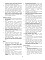
Cutting attachments
1. Use an applicable cutting attachment for the job
in hand.
− Nylon cutting heads (string trimmer heads)
are suitable for trimming lawn grass.
− Metal blades are suitable for cutting weeds,
high grasses, bushes, shrubs, underwood,
thicket, and the like.
− Never use other blades including metal multi-
piece pivoting chains and flail blades. It may
result in serious injury.
2. Always use the cutting attachment guard properly
suited for the cutting attachment used.
3. When using metal blades, avoid "kickback" and
always prepare for an accidental kickback. See
the section "Kickback".
4. When not in use, attach the blade cover onto the
blade. Remove the cover before operation.

9
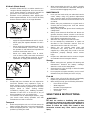
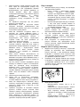
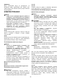
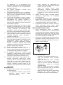
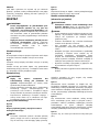
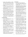
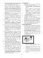
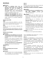
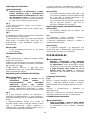
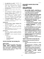
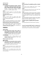
Kickback (Blade thrust)
1. Kickback (blade thrust) is a sudden reaction to a
caught or bound cutting blade. Once it occurs, the
tool is thrown sideway or toward the operator at
great force and it may cause serious injury.
2. Kickback occurs particularly when applying the
blade segment between 12 and 2 o'clock to solids,
bushes and trees with 3 cm or larger diameter.
013863
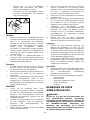
3. To avoid kickback:
− Apply the segment between 8 and 11 o'clock.
− Never apply the segment between 12 and 2
o'clock.
− Never apply the segment between 11 and 12
o'clock and between 2 and 5 o'clock, unless
the operator is well trained and experienced
and does it at his/her own risk.
− Never use cutting blades close to solids,
such as fences, walls, tree trunks and stones.
− Never use cutting blades vertically, for such
operations as edging and trimming hedges.
013864
Vibration
1. People with poor circulation who are exposed to
excessive vibration may experience injury to
blood vessels or the nervous system. Vibration
may cause the following symptoms to occur in the
fingers, hands or wrists: "Falling asleep"
(numbness), tingling, pain, stabbing sensation,
alteration of skin color or of the skin. If any of
these symptoms occur, see a physician!
2. To reduce the risk of "white finger disease", keep
your hands warm during operation and well
maintain the tool and accessories.
Transport
1.
Before transporting the tool, turn it off and remove the
battery cartridge. Attach the cover to the cutting blade.
2. When transporting the tool, carry it in a horizontal
position by holding the shaft.
3. When transporting the tool in a vehicle, properly
secure it to avoid turnover. Otherwise damage to
the tool and other baggage may result.
MAINTENANCE
1. Have your tool serviced by our authorized service
center, always using only genuine replacement
parts. Incorrect repair and poor maintenance can
shorten the life of the tool and increase the risk of
accidents.
2. Before doing any maintenance or repair work or
cleaning the tool, always turn it off and remove
the battery cartridge.
3. Always wear protective gloves when handling the
cutting blade.
4. Always clean dust and dirt off the tool. Never use
gasoline, benzine, thinner, alcohol or the like for
the purpose. Discoloration, deformation or cracks
of the plastic components may result.
5. After each use, tighten all screws and nuts.
6. Do not attempt any maintenance or repair not
described in the instruction manual. Ask our
authorized service center for such work.
7. Always use our genuine spare parts and
accessories only. Using parts or accessories
supplied by a third party may result in the tool
breakdown, property damage and/or serious
injury.
8. Request our authorized service center to inspect
and maintain the tool at regular interval.
Storage
1. Before storing the tool, perform full cleaning and
maintenance. Remove the battery cartridge.
Attach the cover to the cutting blade.
2. Store the tool in a dry and high or locked location
out of reach of children.
3.
Do not prop the tool against something, such as a wall.
Otherwise it may fall suddenly and cause an injury.
First aid
1. Always have a first-aid kit close by. Immediately
replace any item taken from the first aid kit.
2.
When asking for help, give the following information:
− Place of the accident
− What happened
− Number of injured persons
− Nature of the injury
− Your name
SAVE THESE INSTRUCTIONS.
WARNING:
DO NOT let comfort or familiarity with product
(gained from repeated use) replace strict adherence
to safety rules for the subject product. MISUSE or
failure to follow the safety rules stated in this
instruction manual may cause serious personal
injury.

10
ENC007-8
IMPORTANT SAFETY
INSTRUCTIONS
FOR BATTERY CARTRIDGE
1. Before using battery cartridge, read all
instructions and cautionary markings on (1)
battery charger, (2) battery, and (3) product
using battery.
2. Do not disassemble battery cartridge.
3. If operating time has become excessively
shorter, stop operating immediately. It may
result in a risk of overheating, possible burns
and even an explosion.
4. If electrolyte gets into your eyes, rinse them
out with clear water and seek medical
attention right away. It may result in loss of
your eyesight.
5. Do not short the battery cartridge:
(1) Do not touch the terminals with any
conductive material.
(2) Avoid storing battery cartridge in a
container with other metal objects such
as nails, coins, etc.
(3) Do not expose battery cartridge to water
or rain.
A battery short can cause a large current flow,
overheating, possible burns and even a
breakdown.
6. Do not store the tool and battery cartridge in
locations where the temperature may reach or
exceed 50 ゚ C (122 ゚ F).
7. Do not incinerate the battery cartridge even if
it is severely damaged or is completely worn
out. The battery cartridge can explode in a fire.
8. Be careful not to drop or strike battery.
9. Do not use a damaged battery.
10. Follow your local regulations relating to
disposal of battery.
SAVE THESE INSTRUCTIONS.
Tips for maintaining maximum battery life
1. Charge the battery cartridge before
completely discharged.
Always stop tool operation and charge the
battery cartridge when you notice less tool
power.
2.
Never recharge a fully charged battery cartridge.
Overcharging shortens the battery service life.
3. Charge the battery cartridge with room
temperature at 10 ゚ C - 40 ゚ C (50 ゚ F - 104 ゚ F).
Let a hot battery cartridge cool down before
charging it.
4. Charge the battery cartridge once in every six
months if you do not use it for a long period
of time.

11
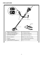
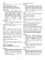
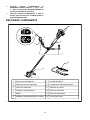
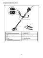
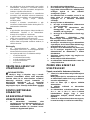
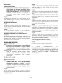
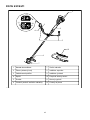
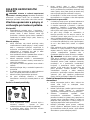
PARTS DESCRIPTION
1
2
3
4
5
6
7
8
9
10
11
12
Battery cartridge
Hanger (suspension point)
Lock-off lever
Switch trigger
Grip
Protector (cutting tool guard)
Cutting tool
Power lamp
Speed indicator
Reverse button
Main power button
Shoulder harness
1
2
3
4
5
6
7
8
9
10
11
12
015572

12
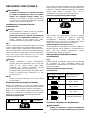
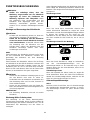
FUNCTIONAL DESCRIPTION
WARNING:
• Always be sure that the tool is switched off
and the battery cartridge is removed before
adjusting or checking function on the tool.
Failure to switch off and remove the battery
cartridge may result in serious personal injury from
accidental start-up.
Installing or removing battery cartridge
CAUTION:
• Always switch off the tool before installing or
removing of the battery cartridge.
• Hold the tool and the battery cartridge firmly
when installing or removing battery cartridge.
Failure to hold the tool and the battery cartridge
firmly may cause them to slip off your hands and
result in damage to the tool and battery cartridge
and a personal injury.
Fig.1
To remove the battery cartridge, slide it from the tool
while sliding the button on the front of the cartridge.
To install the battery cartridge, align the tongue on the
battery cartridge with the groove in the housing and slip
it into place. Insert it all the way until it locks in place
with a little click. If you can see the red indicator on the
upper side of the button, it is not locked completely.
CAUTION:
• Always install the battery cartridge fully until the
red indicator cannot be seen. If not, it may
accidentally fall out of the tool, causing injury to
you or someone around you.
• Do not install the battery cartridge forcibly. If the
cartridge does not slide in easily, it is not being
inserted correctly.
NOTE:
• The tool does not work with only one battery
cartridge.
Tool / battery protection system
The tool is equipped with a tool/battery protection
system. This system automatically cuts off power to the
motor to extend tool and battery life.
The tool will automatically stop during operation if the
tool or battery is placed under one of the following
conditions. In some conditions, the indicators light up.
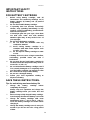
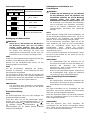
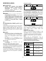
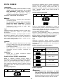
Overload protection
On Off Blinking
015586
If the tool is overloaded by entangled weeds or other
debris, the tool stops automatically, and all of the speed
indicators blink. In this situation, turn the tool off and
stop the application that caused the tool to become
overloaded. Then turn the tool on to restart.
Overheat protection for tool
On Off Blinking
015585
When the tool is overheated, the tool stops
automatically, and all of the speed indicators and the
battery indicator blink about 60 seconds. In this situation,
let the tool cool down before turning the tool on again.
Overdischarge protection
When the battery capacity becomes low, the tool stops
automatically. If the tool does not operate even when
the switches are operated, remove the batteries from
the tool and charge the batteries.
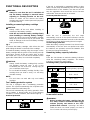
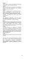
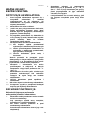
Remaining battery capacity indication
Fig.2
Press the check button to make the battery indicators
show the remaining battery capacities. The battery
indicators correspond to each battery.
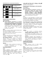
Remaining battery capacity indication
Battery indicator status
Remaining battery capacity
50 % - 100 %
20 % - 50 %
0 % - 20 %
Charge the battery
On Off
Blinking
015452
Power switch action
WARNING:
•
Before inserting the battery cartridge into the
tool, always check to see that the switch trigger
actuates properly and returns to the "OFF"
position when released.
Operating a tool with a
switch that does not actuate properly can lead to
loss of control and serious personal injury.

13
Fig.3
Press and hold the main power button for some
seconds to turn on the tool.
To turn off the tool, press and hold the main power
button again.
Fig.4
To prevent the switch trigger from being accidentally
pulled, a lock-off lever is provided.
To start the tool, grasp the right grip (the lock-off lever is
released by the grasp) and then pull the switch trigger.
To stop the tool, release the switch trigger.
NOTE:
• The tool is automatically turned off after the tool is
left one minute without any operations.
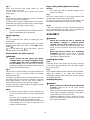
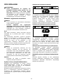
Speed adjusting
Fig.5
You can adjust the tool speed by tapping the main
power button.
Each time you tap the main power button, one of the
speed indicator lights up in order of Turtle(
), middle,
Rabbit(
).
is for low speed and for high speed , and the
middle indicator for middle speed.
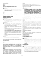
Reverse button for debris removal
WARNING:
• Switch off the tool and remove the battery
cartridge before you remove entangled weeds
or debris which the reverse rotation function
can not remove. Failure to switch off and remove
the battery cartridge may result in serious personal
injury from accidental start-up.
Fig.6
This tool has a reverse button to change the direction of
rotation. It is only for removing weeds and debris
entangled in the tool.
To reverse the rotation, tap the reverse button and pull
the trigger when the tool’s head is stopped. The power
lamp starts blinking, and the tool's head rotates in
reverse direction when you pull the switch trigger.
To return to regular rotation, release the trigger and wait
until the tool's head stops.
NOTE:
• During the reverse rotation, the tool operates only
for a short period of time and then automatically
stops.
• Once the tool is stopped, the rotation returns to
regular direction when you start the tool again.
• If you tap the reverse button while the tool's head
is still rotating, the tool comes to stop and to be
ready for reverse rotation.
Nylon cutting head (optional accessory)
NOTICE:
• The bump feed will not operate properly if the
head is not rotating.
Fig.7
The nylon cutting head is a dual string trimmer head
provided with a bump & feed mechanism.
To cause the nylon cord to feed out, the cutting head
should be bumped against the ground while rotating.
NOTE:
If the nylon cord does not feed out while bumping the
head, rewind/replace the nylon cord by following the
procedures described under “Maintenance.”
ASSEMBLY
WARNING:
• Always be sure that the tool is switched off
and battery cartridge is removed before
carrying out any work on the tool. Failure to
switch off and remove the battery cartridge may
result in serious personal injury from accidental
start-up.
• Never start the tool unless it is completely
assembled. Operation of the tool in a partially
assembled state may result in serious personal
injury from accidental start-up.
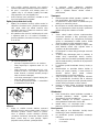
Installing the handle
Fig.8
Insert the shaft of the handle into the grip. Align the
screw hole in the grip with the one in the shaft. Tighten
the screw securely.
Fig.9
Place handle between handle clamp and handle holder.
Adjust the handle to an angle that provides a
comfortable working position and then secure by firmly
hand-tightening knob.
Installing the guard
WARNING:
• Never use the tool without the guard illustrated
in place. Failure to do so can cause serious
personal injury.
• Always use the tool with the approved combination
of the safety equipments. Otherwise contact with a
cutting tool may cause serious injury.
• Permitted combination for the cutting tool and the
guard may differ from country to country. Follow
your region's regulations.

14
For metal blade
Fig.10
Fig.11
For nylon cutting head or plastic blade
CAUTION:
• Take care not to injure yourself on the cutter for
cutting the nylon cord when installing nylon cutting
head or plastic blade.
Fig.12
Fig.13
Align the clamp on the pipe with the protector. And
tighten them with bolts.
Installing the metal blade
(optional accessory)
WARNING:
• The outside diameter of the metal blade must
be 230 mm. Never use any blade exceeding 230
mm in outside diameter.
CAUTION:
• The metal blade must be well polished, free of
cracks or breakage. Polish or replace the metal
blade every three hours of operation.
• Always wear gloves when handling the metal
blade.
• Always attach the blade cover when the tool is not
in use or is being transported.
• The metal blade-fastening nut (with spring washer)
wears out in course of time. If there appears any
wear or deformation on the spring washer, replace
the nut. Ask your local authorized service center to
order it.
• Replace the cup in case of crack or breakage due
to attrition.
NOTICE:
• Be sure to use genuine Dolmar metal blade.
Turn the tool upside down so that you can replace the
metal blade easily.
Fig.14
Mount the metal blade onto the shaft so that the guide
of the receive washer fits in the arbor hole in the metal
blade. Install the clamp washer and secure the metal
blade with the hex nut with 13 to 23 Nm of tightening
torque during holding the receive washer with hex
wrench.
Fig.15
To dismount the metal blade, insert the hex wrench
through the hole on the protector cover and the gear
case. Rotate the receive washer until it is locked with
the hex wrench. Loosen the hex nut (left-hand thread)
with the socket wrench and remove the nut, clamp
washer and hex wrench.
Fig.16
Make sure that the blade is the left way up.
Installing nylon cutting head or plastic blade
(optional accessory)
CAUTION:
• If the nylon cutting head / plastic blade
accidentally impacts a rock or hard object
during operation, stop the tool and inspect for
any damage. If the nylon cutting head / plastic
blade is damaged, replace it immediately. Use
of a damaged cutting tool could result in serious
personal injury.
NOTICE:
• Be sure to use genuine Dolmar nylon cutting head
/ plastic blade.
Turn the tool upside down so that you can replace the
nylon cutting head easily.
Fig.17
Fig.18
Insert the hex wrench through the hole on the motor
housing and rotate the receive washer until it is locked
with the hex wrench. Place the nylon cutting head /
plastic blade onto the threaded spindle directly and
tighten it by turning it counterclockwise. Remove the
hex wrench.
To remove the nylon cutting head / plastic blade, turn it
clockwise while holding the receive washer with the hex
wrench.
Hex wrench storage
Fig.19
When not in use, store the hex wrench as shown in the
figure to keep it from being lost.
OPERATION
Correct handling of tool
WARNING:
• Be extremely careful to maintain control of the
tool at all times. Do not allow the tool to be
deflected toward you or anyone in the work
vicinity. Failure to keep control of the tool could
result in serious injury to the bystander and the
operator.
Correct posture
WARNING:
• Always hold the both grips firmly and position
the tool on your right-hand side so that the
shaft of the left handle is always in front of
your body. Correct positioning of the tool allows
for maximum control and will reduce the risk of
serious personal injury caused by kickback.

15
Fig.20
Fit the shoulder harness and hang the tool firmly on
your right side so that the shaft of the left handle is
always ahead of you.
Attachment of shoulder harness
Fig.21
Wear the shoulder harness on your left shoulder. Make
sure that the buckle cannot be taken off with pulling it off.
Hang the tool as shown.
Fig.22
The buckle is provided with a means of quick release.
Simply squeeze the sides of the buckle to release the
tool.
Adjustment of the hanger position and shoulder
harness
To change the hanger position, loosen the fixing screw
on the hanger with the supplied wrench and then move
the hanger and the cushion. The cushion can be moved
easily by twisting it.
MAINTENANCE
WARNING:
• Always be sure that the tool is switched off
and battery cartridge is removed before
attempting to perform inspection or
maintenance on the tool. Failure to switch off
and remove the battery cartridge may result in
serious personal injury from accidental start-up.
NOTICE:
Never use gasoline, benzine, thinner, alcohol or
the like. Discoloration, deformation or cracks may
result.
Replacing the nylon cord
WARNING:
• Make sure that the cover of the nylon cutting
head is secured to the housing properly as
described below. Failure to properly secure the
cover may cause the nylon cutting head to fly
apart resulting in serious personal injury.
Fig.23
Take off cover from housing, pressing two latches which
are slotted section oppositely on side of housing.
Fig.24
Cut a nylon line in 3-6 m. Fold the cutting line in two
halves, leave one of half longer 80-100 mm than
another.
Fig.25
Hook the middle of the new nylon cord to the notch
located at the center of the spool between the 2
channels provided for the nylon cord.
Wind both ends firmly around the spool in the direction
marked on the head for left hand direction indicated by
LH.
Fig.26
Wind all but about 100 mm of the cords, leaving the
ends temporarily hooked through a notch on the side of
the spool.
Fig.27
Mount the spool on the cover so that the grooves and
protrusions on the spool match up with those on the
cover. Now, unhook the ends of the cord from their
temporary position and feed the cords through the
eyelets to come out of the cover.
Fig.28
Align the protrusion on the underside of the cover with
the slots of the eyelets. Then push the cover firmly onto
the housing to secure it. Make sure the latches fully
spread in the cover.
Replacing the blade for plastic blade
Fig.29
Replace the blade when it is worn out or broken.
To maintain product SAFETY and RELIABILITY, repairs,
any other maintenance or adjustment should be
performed by DOLMAR Authorized Service Centers,
always using DOLMAR replacement parts.

16
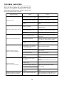
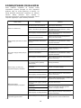
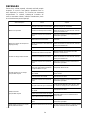
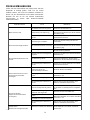
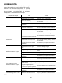
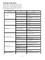
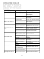
TROUBLE SHOOTING
Before asking for repairs, conduct your own inspection
first. If you find a problem that is not explained in the
manual, do not attempt to dismantle the tool. Instead,
ask Dolmar Authorized Service Centers, always using
Dolmar replacement parts for repairs.
Tighten the nut properly as described
in this manual.
Recharge the battery cartridge. If recharging
is not effective, replace battery cartridge.
Recharge the battery cartridge. If recharging
is not effective, replace battery cartridge.
Cutter blade fastening nut is loose.
Cutter blade is fastened improperly.
The cutter blade is bent,
cracked or worn.
Malfunction status
Motor does not run.
Cause
Battery cartridges are not installed.
Battery problem (under voltage)
Rotation is in reverse.
Overheating.
Battery power is dropping.
Electric or electronic malfunction.
Action
Install the battery cartridges.
Remove the foreign object.
Motor stops running after a little use.
It does not reach maximum RPM.
Cutting tool does not rotate:
stop the machine immediately!
Abnormal vibration:
stop the machine immediately!
Cutting tool and motor cannot stop:
Remove the battery immediately!
Cutter blade fastening nut is loose.
Tighten the nut properly as described
in this manual.
The cutter blade is bent. Replace the cutter blade.
Replace the cutter blade.
The drive system does not work
correctly.
Battery's charge level is low.
Battery is installed improperly.
The drive system does not work
correctly.
Foreign object such as a branch is
jammed between the guard and
the nylon cutting head.
The drive system does not work
correctly.
One end of the nylon cord has
been broken.
The drive system does not work
correctly.
Recharge the battery cartridge. If recharging
is not effective, replace battery cartridge.
Ask your local authorized service center for
repair.
Ask your local authorized service center for
repair.
Change the direction of ratation with the
reversing switch.
Stop using of tool to allow it to cool down.
Install the battery cartridge as described in
this manual.
Ask your local authorized service center for
repair.
Ask your local authorized service center for
repair.
Bump the nylon cutting head against the
ground while it is rotating to cause the cord
to feed.
Remove the battery cartridge and ask your
local authorized service center for repair.
014837

17
OPTIONAL ACCESSORIES
CAUTION:
• These accessories or attachments are
recommended for use with your Dolmar tool
specified in this manual. The use of any other
accessories or attachments might present a risk of
injury to persons. Only use accessory or
attachment for its stated purpose.
If you need any assistance for more details regarding
these accessories, ask your local Dolmar service center.
• Cutter blade
• Nylon cutting head
• Nylon cord (cutting line)
• Plastic blade
• Protector assembly for nylon cutting
• Protector assembly for cutter blade
• Dolmar genuine battery and charger
NOTE:
• Some items in the list may be included in the tool
package as standard accessories. They may differ
from country to country.

18
УКРАЇНСЬКА (Оригінальні інструкції)
Пояснення до загального виду
1-1. Червоний індикатор
1-2. Кнопка
1-3. Касета з акумулятором
2-1. Індикатор акумулятора
2-2. Кнопка ПЕРЕВІРКА
3-1. Головна кнопка живлення
4-1. Розчіпляючий важіль
4-2. Кнопка вимикача
5-1. Головна кнопка живлення
5-2. Індикатор швидкості
6-1. Кнопка зворотного ходу
7-1. Сектор, найбільш ефективний
для різання
8-1. Затиск
8-2. Ручка
8-3. Гвинт
9-1. Затискач ручки
9-2. Гвинт
11-1. Затиск
11-2. Болт
13-1. Різак
13-2. Затиск
13-3. Бо
лт
14-1. Шестигранний ключ
14-2. Гайка
14-3. Ковпачок
14-4. Затискна шайба
14-5. Металева ріжуча пластина
14-6. Опорна шайба
15-1. Шестигранний ключ
15-2. Викрутка з головкою
15-3. Затягнути
17-1. Ріжуча головка з нейлоновим
шнуром
17-2. Металева захисна пластина
17-3. Опорна шайба
17-4. Шестигранний ключ
18-1. Пластикова ріжуча пластина
18-2. Гайка
18-3. Опорна шайба
18-4. Шестигранний ключ
19-1. Шестигранний ключ
21-1. Пряжка
21-2. Ск
оба
22-1. Пряжка
24-1. 80 - 100 мм
ТЕХНІЧНІ ХАРАКТЕРИСТИКИ
Модель AT-3723 U
Тип ручки Велосипедна ручка
Швидкість без навантаження 3500 / 5300 / 6500 хв
-1
Загальна довжина (із ріжучим інструментом) 1754 мм
Застосовний ріжучий інструмент (залежить від країни)
Металева ріжуча
пластина
Ріжуча головка з
нейлоновим шнуром
Пластикова
ріжуча пластина
Діаметр різання 230 мм 350 мм 255 мм
Номінальна напруга 36 В пост. струму
Стандартна касета з акумулятором AP-1815 / AP-1820 AP-183 / AP-1840 / AP-1850
Вага нетто (із металевою ріжучою пластиною) 4,7 кг 5,2 кг
• Через те, що ми не припиняємо програми досліджень і розвитку, наведені тут технічні характеристики можуть бути змінені
без попередження.
• Технічні характеристики приладу та касета з акумулятором можуть відрізнятися в різних країнах.
• Вага разом з касетою з акумулятором відповідно до EPTA-Procedure 01/2003
Шум
Середній рівень
звукового тиску
Середній рівень акустичної потужності
L
PA
(дБ (А)) L
WA
(дБ (A)) Похибка K (дБ (A))
Відповідний
стандарт
Металева ріжуча пластина 75 86 0,4
Пластикова ріжуча пластина 83 92,8 0,6
Ріжуча головка з нейлоновим шнуром
77 90 2,2
2000/14/EC
• Навіть якщо наведений вище рівень звукового тиску менше або дорівнює 80 дБ (A), рівень безпосередньо у місці виконання
роботи може перевищувати 80 дБ (A). Використовуйте засоби захисту органів слуху.
Вібрація Ліва рука Права рука
a
h
(м/с
2
)
Похибка K (м/с
2
)
a
h
(м/с
2
)
Похибка K (м/с
2
)
Відповідний
стандарт
Металева ріжуча пластина 2,5 1,5 2,5 1,5
Пластикова ріжуча пластина 2,5 1,5 2,5 1,5
Ріжуча головка з нейлоновим шнуром
2,5 1,5 2,5 1,5
EN786

19
ENG901-1
•
Заявлене значення вібрації було виміряно у
відповідності до стандартних методів
тестування та може використовуватися для
порівняння одного інструмента з іншим.
• Заявлене значення вібрації може також
використовуватися для попередньої оцінки
впливу.
УВАГА:
• Залежно від умов використання вібрація під час
фактичної роботи інструмента може
відрізнятися від заявленого значення вібрації.
• Забезпечте належні запобіжні заходи для
захисту оператора, що відповідатимуть умовам
використання інструмента (слід брати до уваги
всі складові робочого циклу, такі як час, коли
інструмент вимкнено та коли він починає
працювати на холостому ході під час запуску).
END119-1
Символи
Далі наведені символи, які застосовуються для
позначення обладнання. Перед користуванням
переконайтеся, що Ви розумієте їхнє значення.
・ Будьте особливо уважні та обережні!
・ Читайте інструкцію з експлуатації.
・ Небезпека; пам’ятайте, що предмети
можуть відскочити.
・ Відстань між інструментом і людьми,
що знаходяться поблизу, повинна
становити не менше 15 метрів.
・
Слідкуйте за тим, щоб сторонні особи
знаходилися на небезпечній відстані.
・
Тримайте відстань щонайменше
15 метрів.
・ Уникайте віддачі.
・ Обов'язково надягайте шолом,
захисні окуляри та засоби захисту
органів слуху.
・ Вдягайте захисні рукавиці.
・ Надягайте міцне взуття із підошвами,
що не ковзають. Ми рекомендуємо
захисне взуття зі сталевим носком.
・ Не піддавайте інструмент впливу
вологи.
・ Максимально припустима швидкість
роботи інструмента.
・ Максимально припустима швидкість
робо
ти інструмента.
・ Тільки для країн ЄС
Не викидайте електроприлади або
акумуляторні батареї разом із
побутовим сміттям!
Згідно з Європейськими директивами
про утилізацію електричного та
електронного обладнання та про
утилізацію батарей та акумуляторів і
батарей та акумуляторів, термін
служби яких закінчився, та їх
використанням із дотриманням
національних законів, електричне
обладнання,
батареї та ак
умулятори,
термін служби яких закінчився,
потрібно збирати окремо та
відправляти на екологічно чисті
підприємства з їхньої переробки.
ENH114-1
Тільки для країн Європи
Декларація про відповідність стандартам
ЄС
Компанія Makita наголошує на тому, що
обладнання:
Позначення обладнання:
Акумуляторна газонокосарка
№ моделі / тип: AT-3723 U
Технічні характеристики: див. Таблицю
"ТЕХНІЧНІ ХАРАКТЕРИСТИКИ".
Відповідає таким Європейським Директивам:
2000/14/EC, 2006/42/EC
Обладнання виготовлене відповідно до таких
стандартів або стандартизованих документів:
EN/ISO11806, EN60335
Технічну інформацію відповідно до 2006/42/EC
можна отримати:
Makita, Jan-Baptist Vinkstraat 2, 3070, Бельгія
ENH115-1
Процедура оцінювання відповідності, якої вимагає
Директива 2000/14/EC, відбулася відповідно до
Додатку V.
Із металевою ріжучою пластиною
Заміряний рівень звукової потужності 86 дБ (A)
Гарантований рівень звукової потужності 86 дБ (A)
Пластикова ріжуча пластина
Заміряний рівень звукової потужності 92,8 дБ (A)
Гарантований рівень звукової потужності 93 дБ (A)
ENH115-1
Процедура оцінювання відповідності, якої вимагає
Директива 2000/14/EC, відбулася відповідно до
Додатку VI.
Уповноважений орган:
TÜV Rheinland LGA Products GmbH
Tillystraße 2
90431 Nürnberg, Німеччина
Ідентифікаційний номер: 0197
Із ріжучою головкою з нейлоновим шнуром
Заміряний рівень звукової потужності 90 дБ (A)
Гарантований рівень звукової потужності 92 дБ (A)
15m(50FT)
Cd
Ni-MH
Li-ion

20
16.1.2015
000331
Ясуші Фукайя
Директор
Makita, Jan-Baptist Vinkstraat 2, 3070, Бельгія
GEB068-6
ВАЖЛИВІ ІНСТРУКЦІЇ БЕЗПЕКИ
УВАГА! Прочитайте усі застереження
стосовно техніки безпеки та всі інструкції.
Недотримання цих застережень та інструкцій може
призвести до ураження струмом, виникнення пожежі
та/або може спричинити серйозні травми.
Збережіть усі інструкції з
техніки безпеки та експлуатації
на майбутнє.
Використання за призначенням
1. Акумуляторний тример/кущоріз/кордова
газонокосарка призначені тільки для
стриження трави, бур'яну, кущів та порослі. Не
дозволяється використовувати інструмент за
іншим призначенням, наприклад для
окантовки та стриження живоплоту, оскільки це
може призвести до отримання травм.
Загальні положення
1. Ніколи не дозволяйте особам, які не
ознайомилися з цією інструкцією, а також
людям (у тому числі дітям) з обмеженими
фізичними, сенсорними або розумовими
можливостями та особам із недостатнім
досвідом і знаннями використовувати цей
інструмент. За дітьми слід забезпечити нагляд,
щоб переконатися, що вони не грають з
інструментом.
2. Перш ніж запускати ін
струмент, прочитайте цю
інструкцію з експлуатації, щоб ознайомитися з
правилами користування інструментом.
3. Передавайте інструмент тільки тим особам, які
мають достатній досвід роботи з кущорізами та
кордовими газонокосарками.
4. Разом із інструментом слід також завжди
передавати й цю інструкцію з експлуатації.
5. Інструмент слід завжди використовувати із
максимальною обережністю та увагою.
6.
Ніколи не вик
ористовуйте інструмент після
прийняття ліків чи алкоголю або у разі втоми
чи хворобливого стану.
7. Ніколи не намагайтеся внести зміни до
конструкції інструмента.
8. Дотримуйтеся прийнятих у Вашій країні норм
законодавства щодо належного користування
кущорізами та кордовими газонокосарками.
Засоби індивідуального захисту
013122
1. Надягайте захисний шолом, захисні окуляри та
захисні рукавиці, щоб захистити себе від
уламків, що розлітаються, або від предметів,
що падають.
2. Для запобігання ураженню органів слуху
користуйтеся засобами захисту органів слуху,
наприклад навушниками.
3. Задля безпечної роботи користуйтеся
відповідним одягом та взуттям, наприклад
робочим комбінезоном та міцним взуттям із
підошвами, що
не ко
взають. Не надягайте
прикраси або занадто вільний одяг. Рухомі
деталі можуть захопити вільний одяг, прикраси
або довге волосся.
4. Під час торкання ріжучої пластини надягайте
захисні рукавиці. Ріжуча пластина можете
завдати Вашим рукам серйозної травми.
Безпека робочого місця
1. Використовуйте інструмент тільки вдень за
умов належної видимості. Забороняється
використовувати інструмент у темний час доби
або під час туману.
2. Не використовуйте інструмент у
вибухонебезпечних місцях, наприклад за
наявності легкозаймистих рідин, газів чи пилу.
Інструмент може іскрити, і це може призводити
до займання пилу чи газів.
3. Під час роботи ніколи не стій
те на нестійкій,
слизькій або похилій поверхні. У холодну пору
року будьте обережними, щоб не впасти на
снігу або на льоді, а також подбайте про стійку
опору на ноги.
4. Під час роботи сторонні особи та тварини
повинні знаходитися на відстані не менше ніж
15 м від інструмента. У разі наближення бу
дь-
якої особи або тварини слід негайно зупиняти
інструмент.
5.
Перед тим як почати використовувати
інструмент, слід оглянути робоче місце на
предмет наявності каміння або інших твердих
предметів. Вони можуть відлетіти або
спричинити небезпечну віддачу, що призведе до
серйозних травм та/або пошкодження майна.
Pagina se încarcă...
Pagina se încarcă...
Pagina se încarcă...
Pagina se încarcă...
Pagina se încarcă...
Pagina se încarcă...
Pagina se încarcă...
Pagina se încarcă...
Pagina se încarcă...
Pagina se încarcă...
Pagina se încarcă...
Pagina se încarcă...
Pagina se încarcă...
Pagina se încarcă...
Pagina se încarcă...
Pagina se încarcă...
Pagina se încarcă...
Pagina se încarcă...
Pagina se încarcă...
Pagina se încarcă...
Pagina se încarcă...
Pagina se încarcă...
Pagina se încarcă...
Pagina se încarcă...
Pagina se încarcă...
Pagina se încarcă...
Pagina se încarcă...
Pagina se încarcă...
Pagina se încarcă...
Pagina se încarcă...
Pagina se încarcă...
Pagina se încarcă...
Pagina se încarcă...
Pagina se încarcă...
Pagina se încarcă...
Pagina se încarcă...
Pagina se încarcă...
Pagina se încarcă...
Pagina se încarcă...
Pagina se încarcă...
Pagina se încarcă...
Pagina se încarcă...
Pagina se încarcă...
Pagina se încarcă...
Pagina se încarcă...
Pagina se încarcă...
Pagina se încarcă...
Pagina se încarcă...
Pagina se încarcă...
Pagina se încarcă...
Pagina se încarcă...
Pagina se încarcă...
Pagina se încarcă...
Pagina se încarcă...
Pagina se încarcă...
Pagina se încarcă...
Pagina se încarcă...
Pagina se încarcă...
Pagina se încarcă...
Pagina se încarcă...
Pagina se încarcă...
Pagina se încarcă...
Pagina se încarcă...
Pagina se încarcă...
Pagina se încarcă...
Pagina se încarcă...
Pagina se încarcă...
Pagina se încarcă...
Pagina se încarcă...
Pagina se încarcă...
Pagina se încarcă...
Pagina se încarcă...
Pagina se încarcă...
Pagina se încarcă...
Pagina se încarcă...
Pagina se încarcă...
Pagina se încarcă...
Pagina se încarcă...
Pagina se încarcă...
Pagina se încarcă...
Pagina se încarcă...
Pagina se încarcă...
Pagina se încarcă...
Pagina se încarcă...
Pagina se încarcă...
Pagina se încarcă...
Pagina se încarcă...
Pagina se încarcă...
Pagina se încarcă...
Pagina se încarcă...
Pagina se încarcă...
Pagina se încarcă...
Pagina se încarcă...
Pagina se încarcă...
Pagina se încarcă...
Pagina se încarcă...
-
 1
1
-
 2
2
-
 3
3
-
 4
4
-
 5
5
-
 6
6
-
 7
7
-
 8
8
-
 9
9
-
 10
10
-
 11
11
-
 12
12
-
 13
13
-
 14
14
-
 15
15
-
 16
16
-
 17
17
-
 18
18
-
 19
19
-
 20
20
-
 21
21
-
 22
22
-
 23
23
-
 24
24
-
 25
25
-
 26
26
-
 27
27
-
 28
28
-
 29
29
-
 30
30
-
 31
31
-
 32
32
-
 33
33
-
 34
34
-
 35
35
-
 36
36
-
 37
37
-
 38
38
-
 39
39
-
 40
40
-
 41
41
-
 42
42
-
 43
43
-
 44
44
-
 45
45
-
 46
46
-
 47
47
-
 48
48
-
 49
49
-
 50
50
-
 51
51
-
 52
52
-
 53
53
-
 54
54
-
 55
55
-
 56
56
-
 57
57
-
 58
58
-
 59
59
-
 60
60
-
 61
61
-
 62
62
-
 63
63
-
 64
64
-
 65
65
-
 66
66
-
 67
67
-
 68
68
-
 69
69
-
 70
70
-
 71
71
-
 72
72
-
 73
73
-
 74
74
-
 75
75
-
 76
76
-
 77
77
-
 78
78
-
 79
79
-
 80
80
-
 81
81
-
 82
82
-
 83
83
-
 84
84
-
 85
85
-
 86
86
-
 87
87
-
 88
88
-
 89
89
-
 90
90
-
 91
91
-
 92
92
-
 93
93
-
 94
94
-
 95
95
-
 96
96
-
 97
97
-
 98
98
-
 99
99
-
 100
100
-
 101
101
-
 102
102
-
 103
103
-
 104
104
-
 105
105
-
 106
106
-
 107
107
-
 108
108
-
 109
109
-
 110
110
-
 111
111
-
 112
112
-
 113
113
-
 114
114
-
 115
115
-
 116
116


Dolmar AT3723U Manualul proprietarului
- Categorie
- Unelte electrice
- Tip
- Manualul proprietarului
în alte limbi
- slovenčina: Dolmar AT3723U Návod na obsluhu
- polski: Dolmar AT3723U Instrukcja obsługi
Lucrări înrudite
-
Dolmar ET110C Manualul proprietarului
-
Dolmar ET101C Manualul proprietarului
-
-
-
-
-
-
-
-
Alte documente
-
Makita DUR192L Manual de utilizare
-
-
-
-
-
Husqvarna 215iL Manualul proprietarului
-
Ryobi OBC1820B Original Instructions Manual
-
-
-