Ubiquiti UniFi nanoHD UAP-nanoHD Ghid de inițiere rapidă
- Tip
- Ghid de inițiere rapidă

Compact 802.11ac Wave 2
Enterprise Access Point
Model: UAP-nanoHD

Introduction
Thank you for purchasing the Ubiquiti Networks® UniFi®
802.11ac Wave 2 Enterprise Access Point. This Quick Start
Guide is designed to guide you through installation and
includes warranty terms.
IMPORTANT:
The UAP-nanoHD requires the UniFi
Controller
v5.7 or higher, available at:
www.ubnt.com/download/unifi
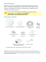
Package Contents
UniFi nanoHD AP Mounting Bracket Ceiling Backing
Plate
Screws
(Qty. 4)
Flat Head Screws
(Qty. 4)
Keps Nuts
(Qty. 4)
Screw Anchors
(Qty. 4)
Gigabit PoE* (48V, 0.5A)
with Mount Bracket
Power Cord*
* Included only in the single-pack of the UAP-nanoHD
TERMS OF USE: All Ethernet cabling runs must use CAT5 (or above). It is the professional
installer’s responsibility to follow local country regulations, including operation within legal
frequency channels, output power, indoor cabling requirements, and Dynamic Frequency
Selection (DFS) requirements.

Installation Requirements
• CAT5 cable
• Phillips screwdriver
• Drill and drill bit (6 mm for wall-mounting or 3 mm for
ceiling-mounting)
• Optional: Drywall or keyhole saw (to cut 18 mm hole for
Ethernet cable feed)
System Requirements
• Microsoft Windows 7/8/10, MacOSX, or Linux
• Java Runtime Environment 1.8 (or above)
• Web Browser: Google Chrome (Other browsers may have
limited functionality.)
• UniFi Controller software v5.7 or higher (available at:
www.ubnt.com/download/unifi)

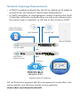
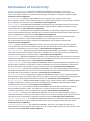
Network Topology Requirements
• A DHCP-enabled network (for the AP to obtain an IP address
as well as for the wireless clients after deployment)
• A UniFi Cloud Key or management station running the UniFi
Controller software, located either on-site and connected to
the same Layer-2 network, or off-site in the cloud or a NOC
US-16-150W
USG-PRO-4
(DHCP Server)
Internet
UAP-nanoHD
UAP-AC-M-PRO
UAP-AC-HD
LAN
WAN
UniFi Cloud Key
(UniFi Controller)
Remote Access to
UniFi Controller
Good
Fair
Poor
Great
Network:
Switches
12
Gateway
Ulizaon
18%
Internet
Capacity
43%
Clients
412
Guests
113
IoT
45
Everything is
great
My Dashboard
Edit Widgets
-24hrs
-24hrs
Max
980
Min
0
Now
Now
Throughput
Latency
ISP Load:
Great
-24hrs
Max
0
Now
Airme
-24hrs
High
Low
Now
Retry Rate
Great
Wi-Fi Load:
225.2 Mbps
125.2 Mbps
1
Wi-Fi Traffic Distribuon
36
6
11
40
44
48
52
56
60
64
100
104
108
112
116
120
124
128
132
136
140
149
153
157
161
165
5 GHz
2.4 GHz
Access Points
20
Last 24 Hrs
Most Acve APs
Office
Back Room
Storage
Roof
Hallway We ...
91 GB
86 GB
53 GB
48 GB
45 GB
Top 5 Applicaons
YouTube
35 Clients
Instagram
19 Clients
Squarespace
17 Clients
Google
12 Clients
Facebook
20 Clients
Top Interference
Hallway We ...
Roof
Storage
51%
45%
44%
Top CPU Usage
Office
Back Room
Home
51%
45%
43%
Most Acve Clients
Wi-Fi Key Metrics
91 Clients
iPhone
87 Clients
Android
45 Clients
MacBook
35 Clients
PC Laptop
12 Clients
iPad
Top Memory Usage
Client Frequency Distribuon
Device Distribuon
HD-Kitchen
HD-Conference
Storage
Roof
Hallway We ...
56.9%
35.6%
34%
28%
24%
Longest Client Upme
Wi-Fi Summary
Roung Ulizaon
Switch Summary
iPad-1
APs Online
Gateway - USG Main
Controller - Office CK
Controller - Office 2 CK
25% CPU Ulizaon
50% CPU Ulizaon
33% CPU Ulizaon
Online
MBP-2
Clients
iPad-2
Ulizaon
Clients
Port Ulizaon
8d 4h 0m
32
24
2d 8h 30m
1,324
2d 5h 15m
64%
1,324
32%
Port Usage
VPN Name
Status
Users
Guests
Purpose
Average Data
Port 1- GB
VPN-LA-PDX
21
2
Corporate
320 GB
Port 2- GB POE+
VPN-LA-PDX2
6
0
VLAN Only
11 GB
Port 3- 10 GB
Remote-Office-1
43
0
VLAN Only
12 GB
120
80
32
HD-Conference
42%
Office - Art Dept
42%
MBP-1
Traffic
Devices
Traffic
2d 3h 10m
248 GB
536
1,248 GB
Port 4- GB POE
Transfer-1
7
12
VLAN Only
0 GB
13
5GHz
50%
13 LAN
03 WLAN
01 WAN
0%
0%
0%
100%
100%
100%
Average Capacity
500 Mbps
Average Airme Ulizaon
8%
Average Spectral Efficiency
2.1 (b/s) Hz
64% 11ac W2
28% 11ac
08% 11n
1300 Mbps
0 Mbps
100%
0%
(b/s) Hz
3.76 (b/s) Hz
Internet Connecon:
30 Mbps
40 Mbps
50 Mbps
20 Mbps
10 Mbps
0 Mbps
-24 hrs
-12 hrs
Now
Download
Theorecal Capacity
Throughput
Portlan
d
SDN
SW-24A
SW-8A
SW-8B
SW-24E
SW-24D
56.9%
35.6%
34%
28%
24%
Most Acve Switches
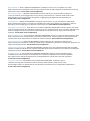
Sample Network Diagram
All UniFi devices support off-site management controllers. For
setup details, see the User Guide on the website:
www.ubnt.com/download/unifi

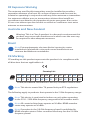
Hardware Overview
LED
LED Color Status
White Factory default, waiting to be adopted.
Flashing White Initializing.
Alternating
White/Blue
Device is busy; do not touch or unplug it.
This usually indicates that a process such
as a firmware upgrade is taking place.
Blue
Indicates the device has been successfully
adopted by a network and is working
properly.
Quickly
Flashing Blue
This is used to locate an AP.
When you click Locate in the UniFi
Controller software, the LED on the AP will
flash. It will also display the location of the
AP on the map.
Steady Blue
with Occasional
Flashing
Indicates the device is in an isolated state
(all WLANs are brought down until an
uplink is found).

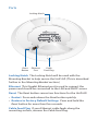
Ports
Ethernet
Port
Reset
Button
Locking Notch
Cable
Feed Plug
Locking Notch The Locking Notch will be used with the
Mounting Bracket to help secure the UniFi AP. (This is described
further in the Mounting Bracket section.)
Ethernet This Gigabit Ethernet port is used to connect the
power and should be connected to the LAN and DHCP server.
Reset The Reset button serves two functions for the UniFi AP:
• Restart Press and release the Reset button quickly.
• Restore to Factory Default Settings Press and hold the
Reset button for more than five seconds.
Cable Feed Plug If your Ethernet cable feeds along the
mounting surface, remove the Cable Feed Plug.

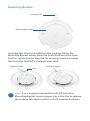
Mounting Bracket
Mounting Bracket
Locking Tab
Locking Tab During installation, the Locking Tab on the
Mounting Bracket moves from the Initial Position to the Final
Position, where the Locking Tab fits securely into the Locking
Notch on the UniFi AP to help prevent theft.
Final Position
Slot
Initial Position
Note:
If you need to remove the UniFi AP from the
Mounting Bracket, insert a paper clip in the Slot to release
the Locking Tab and turn the UniFi AP counterclockwise.

Hardware Installation
The UniFi AP can be mounted on the wall or ceiling. Perform
the steps for the appropriate installation:
Wall Mount
1. Position the Mounting Bracket at the desired location on
the wall with the arrow pointing up.
2. Use a pencil to mark the four mounting holes. Use a 6 mm
drill bit to drill the mounting holes.
Arrow
3. If your Ethernet cable feeds through the wall, then cut or
drill a circle approximately 18 mm in diameter. Then feed
the CAT5 cable through the hole.
25 mm
Note: 25 mm is the distance from the center of the
bottom mounting hole to the center of the cable hole.

4. Insert the Screw Anchors into the 6 mm holes. Secure the
Mounting Bracket to the wall by inserting the Screws into
the anchors.
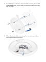
5. If the Ethernet cable runs along the mounting surface,
remove the Cable Feed Plug.

6. Connect the Ethernet cable to the Ethernet port.
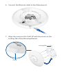
7. Align the arrow on the UniFi AP with the arrow on the
Locking Tab of the Mounting Bracket.
Arrow
Locking Tab

8. Ensure that the UniFi AP is firmly seated on the Mounting
Bracket. Turn the UniFi AP clockwise until it locks into place
and the Locking Tab fits securely into the Locking Notch.

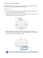
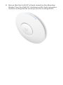
Ceiling Mount
1. Remove the ceiling tile.
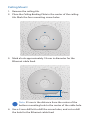
2. Place the Ceiling Backing Plate in the center of the ceiling
tile. Mark the four mounting screw holes.
3. Mark a hole approximately 18 mm in diameter for the
Ethernet cable feed.
25 mm
Note: 25 mm is the distance from the center of the
bottom mounting hole to the center of the cable hole.
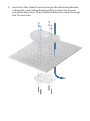
4. Use a 3 mm drill bit to drill the screw holes, and cut or drill
the hole for the Ethernet cable feed.

5. Insert the Flat Head Screws through the Mounting Bracket,
ceiling tile, and Ceiling Backing Plate. Fasten the screws
using the Keps Nuts. Then feed the Ethernet cable through
the 18 mm hole.

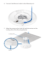
6. Connect the Ethernet cable to the Ethernet port.
7. Align the arrow on the UniFi AP with the arrow on the
Locking Tab of the Mounting Bracket.
Locking Tab
Arrow

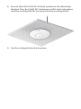
8. Ensure that the UniFi AP is firmly seated on the Mounting
Bracket. Turn the UniFi AP clockwise until it locks into place
and the Locking Tab fits securely into the Locking Notch.
9. Set the ceiling tile back into place.

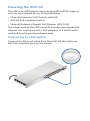
Powering the UniFi AP
The UAP-nanoHD features auto-sensing 802.3af PoE support
and can be powered by any of the following:
• Ubiquiti Networks UniFi Switch with PoE
• 802.3af PoE compliant switch
• Ubiquiti Networks Gigabit PoE Adapter (48V, 0.5A)
The single-pack of the UAP-nanoHD includes one Gigabit PoE
adapter. For multi-pack units, PoE adapters or a UniFi Switch
with PoE may be purchased separately.
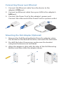
Connecting to a PoE Switch
Connect the Ethernet cable from the UniFi AP directly to an
802.3af-compliant port on the switch.

Connecting Power over Ethernet
1. Connect the Ethernet cable from the device to the
adapter’s POE port.
2. Connect an Ethernet cable from your LAN to the adapter’s
LAN port.
3. Connect the Power Cord to the adapter’s power port.
Connect the other end of the Power Cord to a power outlet.
Mounting the PoE Adapter (Optional)
1. Remove the PoE Mounting Bracket from the adapter, place
the bracket at the desired location, and mark the two holes.
2. Pre-drill the holes if necessary, and secure the bracket
using two fasteners (not included).
3. Align the adapter’s slots with the tabs of the PoE Mounting
Bracket, and then slide the adapterdown.

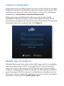
Software Installation
Download and install the latest version of the UniFi Controller
software. Launch it and follow the on-screen instructions. The
software and step-by-step instructions in the User Guide are
available at: www.ubnt.com/download/unifi
After you have installed the software and run the UniFi
Installation Wizard, a login screen will appear for the UniFi
Controller management interface. Enter the Admin Name and
Password that you created and click Sign In.
Mobile App Installation
Ubiquiti Networks also offers the UniFi app, which is available
from the App Store® (iOS) or Google Play
™
Store (Android).
You can use it to provision a UniFi AP for basic functionality
without configuring a UniFi Controller. It also allows seamless
provisioning of APs for remote controllers (controllers not on
the same Layer 2 network) and easy access to local controllers
and those monitored on unifi.ubnt.com

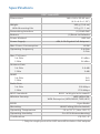
Specifications
UAP-nanoHD
Dimensions 160 x 160 x 32.65 mm
(6.3 x 6.3 x 1.29")
Weight
With Mounting Kits
300 g (10.6 oz)
315 g (11.1 oz)
Networking Interface (1) RJ45 GbE
Buttons (1) Reset to Defaults
Power Method 802.3af
Power Supply 48V, 0.5A Gigabit PoE Adapter*
Max. Power Consumption 10.5W
Operating Frequency 2.4 GHz
5 GHz
Max. TX Power
2.4 GHz
5 GHz
23 dBm
26 dBm
Antenna Gain
2.4 GHz
5 GHz
2.8 dBi
3 dBi
MIMO
2.4 GHz
5 GHz
2x2
4x4
Radio Rate
2.4 GHz
5 GHz
300 Mbps
1733 Mbps
Wi-Fi Standards 802.11 a/b/g/n/ac/ac-wave2
Wireless Security WEP, WPA-PSK,
WPA-Enterprise (WPA/WPA2, TKIP/AES)
BSSID 8 per Radio
Mounting Wall/Ceiling (Kits Included)
Operating Temperature -10 to 70° C (14 to 158° F)
Operating Humidity 5 to 95% Noncondensing
Certications CE, FCC, IC
* Only the single-pack of the UAP-nanoHD includes a PoE adapter.

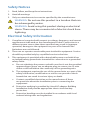
Safety Notices
1. Read, follow, and keep these instructions.
2. Heed all warnings.
3. Only use attachments/accessories specified by the manufacturer.
WARNING: Do not use this product in a location that can
be submerged by water.
WARNING: Avoid using this product during an electrical
storm. There may be a remote risk of electric shock from
lightning.
Electrical Safety Information
1. Compliance is required with respect to voltage, frequency, and current
requirements indicated on the manufacturer’s label. Connection to a
different power source than those specified may result in improper
operation, damage to the equipment or pose a fire hazard if the
limitations are not followed.
2. There are no operator serviceable parts inside this equipment. Service
should be provided only by a qualified service technician.
3. This equipment is provided with a detachable power cord which has
an integral safety ground wire intended for connection to a grounded
safety outlet.
a. Do not substitute the power cord with one that is not the provided
approved type. Never use an adapter plug to connect to a 2-wire
outlet as this will defeat the continuity of the grounding wire.
b. The equipment requires the use of the ground wire as a part of the
safety certification, modification or misuse can provide a shock
hazard that can result in serious injury or death.
c. Contact a qualified electrician or the manufacturer if there
are questions about the installation prior to connecting the
equipment.
d. Protective earthing is provided by Listed AC adapter. Building
installation shall provide appropriate short-circuit backup
protection.
e. Protective bonding must be installed in accordance with local
national wiring rules and regulations.
Pagina se încarcă...
Pagina se încarcă...
Pagina se încarcă...
Pagina se încarcă...
Pagina se încarcă...
Pagina se încarcă...
Pagina se încarcă...
Pagina se încarcă...
-
 1
1
-
 2
2
-
 3
3
-
 4
4
-
 5
5
-
 6
6
-
 7
7
-
 8
8
-
 9
9
-
 10
10
-
 11
11
-
 12
12
-
 13
13
-
 14
14
-
 15
15
-
 16
16
-
 17
17
-
 18
18
-
 19
19
-
 20
20
-
 21
21
-
 22
22
-
 23
23
-
 24
24
-
 25
25
-
 26
26
-
 27
27
-
 28
28


Ubiquiti UniFi nanoHD UAP-nanoHD Ghid de inițiere rapidă
- Tip
- Ghid de inițiere rapidă
în alte limbi
Lucrări înrudite
-
Ubiquiti Networks Réseau de points de UAP-AC-LITE-5 accès Manual de utilizare
-
Ubiquiti UAP-IW-HD Manualul utilizatorului
-
Ubiquiti UAP-AC-PRO Ghid de inițiere rapidă
-
-
-
-
-
-
-
Ubiquiti US-XG-6POE Ghid de inițiere rapidă
Alte documente
-
-
-
Tenda TEF1109TP-8-102W Ghid de instalare
-
Silvercrest SAB 160 A1 Operating Instructions Manual
-
-
IKEA TRADFRI Manual de utilizare
-
Sennheiser CX 400BT True Wireless Instrucțiuni de utilizare
-
Vaisala CA10 Manual de utilizare