
Enterprise WiFi System
Models:
UAP/UAP-LR (Long Range)


1
Introduction
Introduction
Thank you for purchasing the Ubiquiti Networks
™
UniFi
™
Enterprise
WiFi System. The UniFi Enterprise WiFi System includes the UniFi
Controller software that allows you to manage your wireless
network using your web browser.
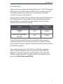
This Quick Start Guide is for use with the following UniFi Enterprise
WiFi System Access Point models. Unless otherwise needed to
specify differences between the two models, this Quick Start
Guide will refer to both as UniFi AP.
Model
Maximum Power
Consumption
Maximum TX
Power
UniFi AP
(UAP)
4 W 20 dBm
UniFi AP Long Range
(UAP-LR)
6 W 27 dBm
The UniFi Enterprise WiFi System also includes the necessary
hardware for mounting the unit on a wall or a ceiling. The UniFi
Enterprise WiFi System supports Passive PoE, which works with the
included PoE adapter.
If you want to power the UniFi AP from an 802.3af compliant
switch, Ubiquiti Networks offers the optional Instant 802.3af
Adapter to instantly transform any PoE device into a fully 48V,
802.3af compliant product. Product details are available on our
website at http://ubnt.com/8023af

2
UniFi
™
AP/AP-LR Quick Start Guide
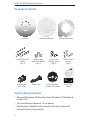
Package Contents
UniFi AP Wall-Mount Bracket Ceiling-Mount Plate
M3x50 Flat Head
Screws
(Qty. 3)
M3 Keps Nuts
with Tooth Washer
(Qty. 3)
M2.9x20 Self
Tapping Screws
(Qty. 3)
M3x20 Screw
Anchors
(Qty. 3)
Enterprise WiFi System
Models:
UAP/UAP-LR (Long Range)
PoE Adapter
(24V, 0.5A)
Power Cord UniFi Controller
CD with User Guide
Quick Start
Guide
System Requirements
• Microsoft Windows XP, Windows Vista, Windows 7, Windows 8,
or Mac OS X
• Java Runtime Environment 1.6 (or above)
• Web Browser: Mozilla Firefox, Google Chrome, or Microsoft
Internet Explorer 8 (or above)

3
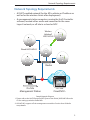
Network Topology Requirements
Network Topology Requirements
• A DHCP-enabled network (for the AP to obtain an IP address as
well as for the wireless clients after deployment)
• A management station computer running the UniFi Controller
software, located either onsite and connected to the same
Layer-2 network, or off-site in a cloud or NOC
or
Router
O-Site
Cloud/NOC
2
On-Site
Management Station
Wired UAP/UAP-LR
Wireless
Uplinked
1
UAP/UAP-LR
Sample Network Diagram
1. Please refer to the UniFi Enterprise WiFi System User Guide | UAP/UAP-LR on the
CD for setting up wireless-linked APs.
2. All UniFi APs support off-site management controllers. See the User Guide for
setup details.

4
UniFi
™
AP/AP-LR Quick Start Guide
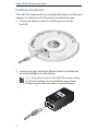
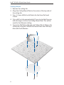
Hardware Installation
The UniFi AP is powered by the included PoE (Power over Ethernet)
adapter. To install the UniFi AP, perform the following steps:
1. Connect an Ethernet cable to the Ethernet port on the
UniFi AP.
2. Connect the other end of the Ethernet cable to the Ethernet
port labeled PoE on the PoE Adapter.
Note: If you plan to mount the UniFi AP on your ceiling,
perform the ceiling mount installation steps before
connecting the Ethernet cable to the PoE Adapter.

5
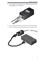
Hardware Installation
3. Connect an Ethernet cable from your LAN to the Ethernet port
labeled LAN on the PoE Adapter.
4. Connect the power cord to the power port on the PoE Adapter.
Connect the other end to of the power cord to a power outlet.

6
UniFi
™
AP/AP-LR Quick Start Guide
Mounting the Access Point
The UniFi AP can be wall-mounted or mounted on a ceiling.
Perform the following steps for the appropriate installation:
Wall-Mount
1. Align the Wall-Mount Bracket with the Wall Mount text facing
up. There are horizontal and vertical lines on the bracket to
help with orientation.
2. Use a pencil to mark the holes on the wall.
3. Use a 6 mm drill bit to drill the holes in the wall.
4. Insert the 3 M3x20 Screw Anchors into the wall.
5. Secure the Wall-Mount Bracket to the wall by inserting the
M2.9x20 Self Tapping Screws into the anchors.

7
Hardware Installation
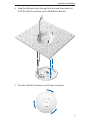
6. Align the notches on the UniFi AP with the notches on the
Wall-Mount Bracket.
7. Turn the UniFi AP clockwise until it locks into place.

8
UniFi
™
AP/AP-LR Quick Start Guide
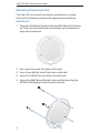
Ceiling-Mount
1. Remove the ceiling tile.
2. Align the Ceiling-Mount Plate to the center of the top side of
the ceiling tile.
3. Use a 3.5 mm drill bit to drill holes for the three flat head
screws.
4. Cut or drill a circle approximately 25 mm in size that lines up
with the larger circle on the Ceiling-Mount Plate. This will be
used for the Ethernet cabling.
5. Secure the Wall-Mount Bracket and Ceiling-Mount Plate to the
ceiling tile using the 3 M3x50 Flat Head Screws and 3 M3 Keps
Nuts with Tooth Washers.

9
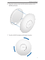
Hardware Installation
6. Feed the Ethernet cable through the hole and then align the
UniFi AP with the notches on the Wall-Mount Bracket.
7. Turn the UniFi AP clockwise until it locks into place.

10
UniFi
™
AP/AP-LR Quick Start Guide
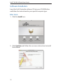
Software Installation
Insert the UniFi Controller software CD into your CD-ROM drive
and follow the instructions for your specific computer type.
Mac Users
1. Click the Install icon.
2. Click Continue and follow the on-screen instructions to install
the software.

11
Software Installation
3. Go to Go > Applications and double-click the UniFi icon.
Proceed to Configuring the UniFi Controller Software on page 13.
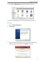
PC Users
1. Launch UniFi-installer.exe.
2. Click Install.
3. If your computer doesn't have Java 1.6 or above installed, you
will be prompted to install it. Click Install to continue.

12
UniFi
™
AP/AP-LR Quick Start Guide
4. Click Next.
5. Ensure that the Start UniFi Controller after installation option is
checked and click Finish.
Note: The UniFi Controller software can also be launched
from Start > All Programs.

13
Software Installation
Configuring the UniFi Controller Software
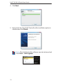
1. The UniFi Controller software startup will begin. When the
option becomes available, click Launch a Browser to Manage
Wireless Network.
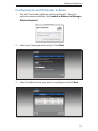
2. Select your language and country. Click Next.
3. Select the devices that you want to configure and click Next.

14
UniFi
™
AP/AP-LR Quick Start Guide
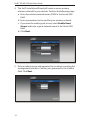
4. The UniFi Installation Wizard will create a secure primary
wireless network for your devices. Perform the following steps:
a. Enter the wireless network name (SSID) in the Secure SSID
field.
b. Enter a passphrase to be used for your primary network.
c. If you want to enable guest access, select Enable Guest
Access and enter a guest network name in the Guest SSID
field.
d. Click Next.
5. Enter an admin name and password to use when accessing the
management interface. Confirm your password in the Confirm
field. Click Next.

15
Software Installation
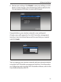
6. Review your settings. Click Finish to save your settings, or click
Back to make changes. Once finished you will be redirected to
the management interface via your web browser.
Congratulations, your wireless network is now configured.
A login screen will appear for the UniFi Controller management
interface. Enter the Admin Name and Password that you created
and click Login.
You can manage your wireless network and view network statistics
using the UniFi Controller management interface. For information
on configuring and using the UniFi Controller software, refer to the
User Guide located on the CD.

16
UniFi
™
AP/AP-LR Quick Start Guide
Installer Compliance Responsibility
Devices must be professionally installed and it is the professional
installer's responsibility to make sure the device is operated within
local country regulatory requirements.
Safety Notices
1. Read, follow, and keep these instructions.
2. Heed all warnings.
3. Only use attachments/accessories specified by the manufacturer.
WARNING: Do not use this product in location that can be
submerged by water.
WARNING: Avoid using this product during an electrical storm.
There may be a remote risk of electric shock from lightning.
Electrical Safety Information
1. Compliance is required with respect to voltage, frequency, and current
requirements indicated on the manufacturer’s label. Connection to a
different power source than those specified may result in improper
operation, damage to the equipment or pose a fire hazard if the
limitations are not followed.
2. There are no operator serviceable parts inside this equipment. Service
should be provided only by a qualified service technician.
3. This equipment is provided with a detachable power cord which has
an integral safety ground wire intended for connection to a grounded
safety outlet.
a. Do not substitute the power cord with one that is not the provided
approved type. Never use an adapter plug to connect to a 2-wire
outlet as this will defeat the continuity of the grounding wire.
b. The equipment requires the use of the ground wire as a part of the
safety certification, modification or misuse can provide a shock
hazard that can result in serious injury or death.
c. Contact a qualified electrician or the manufacturer if there are
questions about the installation prior to connecting the equipment.
d. Protective earthing is provided by Listed AC adapter. Building
installation shall provide appropriate short-circuit backup
protection.
e. Protective bonding must be installed in accordance with local
national wiring rules and regulations.

17
Compliance
Compliance
FCC
Changes or modifications not expressly approved by the party responsible
for compliance could void the user’s authority to operate the equipment.
This device complies with Part 15 of the FCC Rules. Operation is subject to
the following two conditions:
1. This device may not cause harmful interference, and
2. This device must accept any interference received, including
interference that may cause undesired operation.
NOTE: This equipment has been tested and found to comply with the
limits for a Class A digital device, pursuant to part 15 of the FCC Rules.
These limits are designed to provide reasonable protection against
harmful interference when the equipment is operated in a commercial
environment. This equipment generates, uses, and can radiate radio
frequency energy and, if not installed and used in accordance with
the instruction manual, may cause harmful interference to radio
communications. Operations of this equipment in a residential area is likely
to cause harmful interference in which case the user will be required to
correct the interference at his own expense.
For MPE and antenna usage details, please visit our website at
www.ubnt.com/products
Industry Canada
This Class A digital apparatus complies with Canadian ICES-003.
To reduce potential radio interference to other users, the antenna
type and its gain should be so chosen that the equivalent isotropically
radiated power (e.i.r.p.) is not more than that permitted for successful
communication.
This device complies with Industry Canada licence-exempt RSS standard(s).
Operation is subject to the following two conditions:
1. This device may not cause interference, and
2. This device must accept any interference, including interference that
may cause undesired operation of the device.

18
UniFi
™
AP/AP-LR Quick Start Guide
Cet appareil numérique de la classe A est confrome à la norme NMB-003
Canada.
Pour réduire le risque d’interférence aux autres utilisateurs, le type
d’antenne et son gain doivent être choisies de façon que la puissance
isotrope rayonnée équivalente (PIRE) ne dépasse pas ce qui est nécessaire
pour une communication réussie.
Cet appareil est conforme à la norme RSS Industrie Canada exempts de
licence norme(s). Son fonctionnement est soumis aux deux conditions
suivantes:
1. Cet appareil ne peut pas provoquer d’interférences et
2. Cet appareil doit accepter toute interférence, y compris les
interférences qui peuvent causer un mauvais fonctionnement du
dispositif.
RF Exposure Warning
The antennas used for this transmitter must be installed to provide a
separation distance of at least 20 cm from all persons and must not be
located or operating in conjunction with any other antenna or transmitter.
Les antennes utilisées pour ce transmetteur doivent être installé en
considérant une distance de séparation de toute personnes d'au moins
20 cm et ne doivent pas être localisé ou utilisé en conflit avec tout autre
antenne ou transmetteur.
CE Marking
CE marking on this product represents the product is in compliance with
all directives that are applicable to it.
Alert Sign (!) Follows CE Marking
Alert sign must be indicated if a restriction on use applied to the product
and it must follow the CE marking.
Pagina se încarcă...
Pagina se încarcă...
Pagina se încarcă...
Pagina se încarcă...
-
 1
1
-
 2
2
-
 3
3
-
 4
4
-
 5
5
-
 6
6
-
 7
7
-
 8
8
-
 9
9
-
 10
10
-
 11
11
-
 12
12
-
 13
13
-
 14
14
-
 15
15
-
 16
16
-
 17
17
-
 18
18
-
 19
19
-
 20
20
-
 21
21
-
 22
22
-
 23
23
-
 24
24


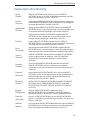
Ubiquiti UniFi AP Long Range Ghid de inițiere rapidă
- Tip
- Ghid de inițiere rapidă
- Acest manual este potrivit și pentru
în alte limbi
Lucrări înrudite
-
Ubiquiti Networks UniFi Manualul utilizatorului
-
Ubiquiti UniFI UAP-AC Ghid de inițiere rapidă
-
Ubiquiti UAP-PRO Ghid de inițiere rapidă
-
-
-
Ubiquiti Networks UAP-AC Manualul utilizatorului
-
-