
Enterprise Gateway Router
with Gigabit Ethernet
Model: USG

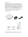
Introduction
Thank you for purchasing the Ubiquiti Networks® UniFi®
Security Gateway, which is part of the UniFi Enterprise System.
The UniFi Enterprise System includes the UniFi Controller
software, which allows you to manage your network using a
web browser. The UniFi Controller software and User Guide are
available for download at downloads.ubnt.com/unifi
This Quick Start Guide includes the warranty terms and is for
use with the UniFi Security Gateway, model USG.
Package Contents
UniFi Security Gateway Power Adapter
(12V, 1A)
Power Cord
Screws
(M2.9x20, Qty. 2)
Screw Anchors
(M2.9, Qty. 2)
Quick Start Guide
TERMS OF USE: All Ethernet cabling runs must use CAT5 (or above). It is the customer’s
responsibility to follow local country regulations and indoor cabling requirements.

UniFi Controller System Requirements
• Microsoft Windows 8, MacOSX, or Linux
• Java Runtime Environment 1.6 (or above)
• Web Browser: Google Chrome, Mozilla Firefox, or Microsoft
Internet Explorer 10 (or above)
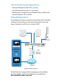
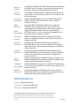
Network Requirements
A management station computer running the UniFi Controller
software, located either on-site and connected to the same
Layer-2 network, or off-site in a cloud or NOC.
or
UniFi Switch
UniFi
Security
Gateway
Internet
O-Site
Cloud/NOC
On-Site
Management
Station
UAP-AC UAP-PRO
UAP-Outdoor
LAN
WAN
Sample Network Diagram
All UniFi devices support off-site management controllers.
For setup details, see the User Guide on our website at:
documentation.ubnt.com/unifi

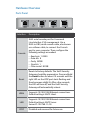
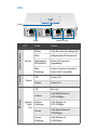
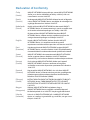
Hardware Overview
Ports Panel
Interface Description
Console
RJ45 serial console port for Command
Line Interface (CLI) management. Use a
RJ45-to-DB9, serial console cable, also known
as a rollover cable, to connect the Console
port to your computer. Then configure the
following settings as needed:
• Baud rate 115200
• Data bits 8
• Parity NONE
• Stop bits 1
• Flow control NONE
Reset
Resets to factory defaults. The UniFi Security
Gateway should be powered on. Press and hold
the Reset button for about 10seconds until the
right LED on the VOIP port starts flashing and
then becomes solidly lit. After a few seconds,
the LED will turn off, and the UniFi Security
Gateway will automatically reboot.
WAN
Supports 10/100/1000 Ethernet connections.
Default setting is DHCP client.
LAN
Supports 10/100/1000 Ethernet connections.
Default setting is DHCP Server.
Server IP: 192.168.1.1/24
VOIP Disabled and reserved for future use.

LEDs
Power Speed/Link/Act
Status
LED State Status
Status Indicator
Status
White Fully Booted; Not Adopted
Blue Adopted and Provisioned
Alternating
White/Blue
Device Firmware is
Upgrading
Blue
Flashing
Device Locator Activated
from UniFi Controller
Console
Power
Off Power Off
Green Power On
Ethernet
Speed/
Link/
Act
Off No Link
Amber
Link Established at
10/100 Mbps
Amber
Flashing
Link Activity at
10/100 Mbps
Green
Link Established at
1000 Mbps
Green
Flashing
Link Activity at
1000 Mbps

Hardware Installation
The UniFi Security Gateway can be used on a level, stable
surface, or mounted to a wall with the included screws
and anchors. If the UniFi Security Gate is not going to be
wall-mounted, skip to the section, Connecting Power.
Note: Keep 20 mm of clearance around the UniFi
Security Gateway for adequate airflow.
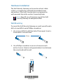
Wall-Mounting
To mount the UniFi Security Gateway on a wall, you will need a
drill, a 6mm drill bit, and a Phillips screwdriver.
1. Use a 6 mm drill bit to drill two holes 90 mm apart. Insert a
Screw Anchor into each hole.
90 mm
2. Use a Phillips screwdriver to secure a Screw into each
anchor. Leave a clearance of approximately 3 mm between
the screw head and the wall.
3 mm
*640-00120-01*
640-00120-01

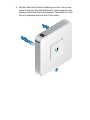
3. Position the UniFi Security Gateway over the Screws, and
insert the Screws into the wall-mount slots located on the
bottom of the UniFi Security Gateway. Then slide the UniFi
Security Gateway down to lock it into place.
12V DC

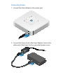
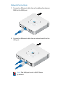
Connecting Power
1. Connect the Power Adapter to the power port.
2. Connect the Power Cord to the Power Adapter. Connect the
other end of the Power Cord to a grounded powersource.

Network Connections
1. Connect an Ethernet cable from a broadband modem or
WAN to the WAN port.
2. Connect an Ethernet cable from a network switch to the
LAN port.
Note: The LAN port is set to DHCP Server
by default.

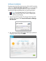
Software Installation
Download and install the latest version of the UniFi Controller
software at: downloads.ubnt.com/unifi From a management
station computer connected to the same Layer 2 network,
launch the installer and follow the on-screen instructions.
Note: If you already have UniFi Controller v4.x or
higher installed, skip to the section, Adopting the
UniFi Security Gateway.
1. Launch the UniFi Controller. The Ubiquiti UniFi Controller
window will appear. Click Launch a Browser to Manage
the Network.
2. The UniFi Setup Wizard will appear. Select your preferred
language and country. Click NEXT.

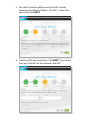
3. The UniFi Controller will discover the UniFi Security
Gateway with default IP Address,192.168.1.1. Select the
device, and click NEXT.
4. Create an SSID and Security Key. Click NEXT. If you do not
have any UniFi APs on the network, click SKIP.

5. Create an Admin Name and Password for UniFi Controller
access. Confirm the Password, and click NEXT.
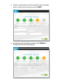
6. Review the UniFi Controller settings. Click FINISH to
complete the UniFi Setup Wizard.

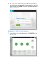
7. The login screen for the UniFi Controller will appear. Enter
the Admin Name and Password that you created in the UniFi
Setup Wizard. Click LOGIN. The UniFi Controller dashboard
window will appear.
Adopting the UniFi Security Gateway
1. From the UniFi Controller dashboard, click DEVICES in the
left menu bar.

2. In the Devices window, locate UniFi Gateway in the list of
devices under the Model column. To adopt and provision
the gateway, click ADOPT.
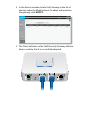
3. The Status Indicator on the UniFi Security Gateway will turn
blue to confirm that it is successfully adopted.

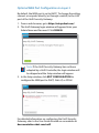
Optional WAN Port Configuration via Layer 3
By default, the WAN port is set to DHCP. To change the setting,
connect a computer directly (or through a switch) to the LAN
port of the UniFi Security Gateway.
1. From a web browser, go to https://setup.ubnt.com/
2. The UniFi Gateway login window will appear. Enter your
Admin Name and Password. Click SIGN IN.
Note: If the UniFi Security Gateway has not been
adopted by a UniFi Controller, the login window will
be skipped and the Setup window will appear.
3. In the Setup window, click EDIT CONFIGURATION to
configure the WAN port to DHCP, Static IP, or PPPoE.
For detailed information on configuring the UniFi Security
Gateway, refer to the User Guide located on our website at:
documentation.ubnt.com/unifi

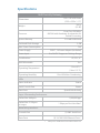
Specifications
UniFi Security Gateway
Dimensions
135 x 135 x 28.3 mm
(5.32 x 5.32 x 1.11")
Weight
366 g
(.81 lb)
Processor
Dual-Core 500 MHz,
MIPS64 with Hardware Acceleration for
Packet Processing
System Memory 512 MB DDR2 RAM
On-Board Flash Storage 2 GB
Max. Power Consumption 7 W
Power Supply 12VDC, 1A Power Adapter (Included)
Power Input 9 to 24VDC Supported Voltage Range
Certications CE, FCC, IC
Wall-Mountable Yes
Operating Temperature
-10 to 45° C
(14 to 113° F)
Operating Humidity 10 to 90% Non-Condensing
LEDs
Status Indicator Status
Serial Console Port Power
Data Ports Speed/Link/Activity
Layer 3 Forwarding Performance
Packet Size: 64 Bytes 1,000,000 pps
Packet Size: 512 Bytes
or Larger
1 Gbps per Port Line Rate*
Networking Interfaces
Console Port (1) RJ45 Serial Port
Data Ports (3) 10/100/1000 Ethernet Ports*
* VoIP port is disabled and reserved for future use.

Safety Notices
1. Read, follow, and keep these instructions.
2. Heed all warnings.
3. Only use attachments/accessories specified by the manufacturer.
WARNING: Do not use this product in location that can
be submerged by water.
WARNING: Avoid using this product during an electrical
storm. There may be a remote risk of electric shock from
lightning.
Electrical Safety Information
1. Compliance is required with respect to voltage, frequency, and current
requirements indicated on the manufacturer’s label. Connection to a
different power source than those specified may result in improper
operation, damage to the equipment or pose a fire hazard if the
limitations are not followed.
2. There are no operator serviceable parts inside this equipment. Service
should be provided only by a qualified service technician.
3. This equipment is provided with a detachable power cord which has
an integral safety ground wire intended for connection to a grounded
safety outlet.
a. Do not substitute the power cord with one that is not the provided
approved type. Never use an adapter plug to connect to a 2-wire
outlet as this will defeat the continuity of the grounding wire.
b. The equipment requires the use of the ground wire as a part of the
safety certification, modification or misuse can provide a shock
hazard that can result in serious injury or death.
c. Contact a qualified electrician or the manufacturer if there
are questions about the installation prior to connecting the
equipment.
d. Protective earthing is provided by Listed AC adapter. Building
installation shall provide appropriate short-circuit backup
protection.
e. Protective bonding must be installed in accordance with local
national wiring rules and regulations.

Limited Warranty
UBIQUITI NETWORKS, Inc (“UBIQUITI NETWORKS”) warrants that the
product(s) furnished hereunder (the “Product(s)”) shall be free from defects
in material and workmanship for a period of one (1) year from the date
of shipment by UBIQUITI NETWORKS under normal use and operation.
UBIQUITI NETWORKS’ sole and exclusive obligation and liability under
the foregoing warranty shall be for UBIQUITI NETWORKS, at its discretion,
to repair or replace any Product that fails to conform to the above
warranty during the above warranty period. The expense of removal and
reinstallation of any Product is not included in this warranty. The warranty
period of any repaired or replaced Product shall not extend beyond its
original term.
Warranty Conditions
The above warranty does not apply if the Product:
(I) has been modified and/or altered, or an addition made thereto,
except by Ubiquiti Networks, or Ubiquiti Networks’ authorized
representatives, or as approved by Ubiquiti Networks in writing;
(II) has been painted, rebranded or physically modified in any way;
(III) has been damaged due to errors or defects in cabling;
(IV) has been subjected to misuse, abuse, negligence, abnormal physical,
electromagnetic or electrical stress, including lightning strikes, or
accident;
(V) has been damaged or impaired as a result of using third party
firmware;
(VI) has no original Ubiquiti MAC label, or is missing any other original
Ubiquiti label(s); or
(VII) has not been received by Ubiquiti within 30 days of issuance of
the RMA.
In addition, the above warranty shall apply only if: the product has been
properly installed and used at all times in accordance, and in all material
respects, with the applicable Product documentation; all Ethernet cabling
runs use CAT5 (or above), and for outdoor installations, shielded Ethernet
cabling is used, and for indoor installations, indoor cabling requirements
are followed.
Returns
No Products will be accepted for replacement or repair without obtaining
a Return Materials Authorization (RMA) number from UBIQUITI NETWORKS
during the warranty period, and the Products being received at UBIQUITI
NETWORKS’ facility freight prepaid in accordance with the RMA process of
UBIQUITI NETWORKS. Products returned without an RMA number will not
be processed and will be returned freight collect or subject to disposal.
Information on the RMA process and obtaining an RMA number can be
found at: www.ubnt.com/support/warranty.

Disclaimer
EXCEPT FOR ANY EXPRESS WARRANTIES PROVIDED HEREIN, UBIQUITI
NETWORKS, ITS AFFILIATES, AND ITS AND THEIR THIRD PARTY DATA,
SERVICE, SOFTWARE AND HARDWARE PROVIDERS HEREBY DISCLAIM
AND MAKE NO OTHER REPRESENTATION OR WARRANTY OF ANY KIND,
EXPRESS, IMPLIED OR STATUTORY, INCLUDING, BUT NOT LIMITED TO,
REPRESENTATIONS, GUARANTEES, OR WARRANTIES OF MERCHANTABILITY,
ACCURACY, QUALITY OF SERVICE OR RESULTS, AVAILABILITY,
SATISFACTORY QUALITY, LACK OF VIRUSES, QUIET ENJOYMENT, FITNESS
FOR A PARTICULAR PURPOSE AND NON-INFRINGEMENT AND ANY
WARRANTIES ARISING FROM ANY COURSE OF DEALING, USAGE OR
TRADE PRACTICE IN CONNECTION WITH SUCH PRODUCTS AND SERVICES.
BUYER ACKNOWLEDGES THAT NEITHER UBIQUITI NETWORKS NOR
ITS THIRD PARTY PROVIDERS CONTROL BUYER’S EQUIPMENT OR THE
TRANSFER OF DATA OVER COMMUNICATIONS FACILITIES, INCLUDING
THE INTERNET, AND THAT THE PRODUCTS AND SERVICES MAY BE
SUBJECT TO LIMITATIONS, INTERRUPTIONS, DELAYS, CANCELLATIONS
AND OTHER PROBLEMS INHERENT IN THE USE OF COMMUNICATIONS
FACILITIES. UBIQUITI NETWORKS, ITS AFFILIATES AND ITS AND THEIR THIRD
PARTY PROVIDERS ARE NOT RESPONSIBLE FOR ANY INTERRUPTIONS,
DELAYS, CANCELLATIONS, DELIVERY FAILURES, DATA LOSS, CONTENT
CORRUPTION, PACKET LOSS, OR OTHER DAMAGE RESULTING FROM ANY
OF THE FOREGOING. In addition, UBIQUITI NETWORKS does not warrant
that the operation of the Products will be error-free or that operation will
be uninterrupted. In no event shall UBIQUITI NETWORKS be responsible
for damages or claims of any nature or description relating to system
performance, including coverage, buyer’s selection of products (including
the Products) for buyer’s application and/or failure of products (including
the Products) to meet government or regulatory requirements.
Limitation of Liability
EXCEPT TO THE EXTENT PROHIBITED BY LOCAL LAW, IN NO EVENT WILL
UBIQUITI OR ITS SUBSIDIARIES, AFFILIATES OR SUPPLIERS BE LIABLE FOR
DIRECT, SPECIAL, INCIDENTAL, CONSEQUENTIAL OR OTHER DAMAGES
(INCLUDING LOST PROFIT, LOST DATA, OR DOWNTIME COSTS), ARISING
OUT OF THE USE, INABILITY TO USE, OR THE RESULTS OF USE OF THE
PRODUCT, WHETHER BASED IN WARRANTY, CONTRACT, TORT OR OTHER
LEGAL THEORY, AND WHETHER OR NOT ADVISED OF THE POSSIBILITY OF
SUCH DAMAGES.

Note
Some countries, states and provinces do not allow exclusions of implied
warranties or conditions, so the above exclusion may not apply to you.
You may have other rights that vary from country to country, state to
state, or province to province. Some countries, states and provinces do not
allow the exclusion or limitation of liability for incidental or consequential
damages, so the above limitation may not apply to you. EXCEPT TO
THE EXTENT ALLOWED BY LOCAL LAW, THESE WARRANTY TERMS DO
NOT EXCLUDE, RESTRICT OR MODIFY, AND ARE IN ADDITION TO, THE
MANDATORY STATUTORY RIGHTS APPLICABLE TO THE LICENSE OF ANY
SOFTWARE (EMBEDDED IN THE PRODUCT) TO YOU. The United Nations
Convention on Contracts for the International Sale of Goods shall not apply
to any transactions regarding the sale of the Products.
Compliance
FCC
Changes or modifications not expressly approved by the party responsible
for compliance could void the user’s authority to operate the equipment.
This device complies with Part 15 of the FCC Rules. Operation is subject to
the following two conditions:
1. This device may not cause harmful interference, and
2. This device must accept any interference received, including
interference that may cause undesired operation.
NOTE: This equipment has been tested and found to comply with the
limits for a Class A digital device, pursuant to part 15 of the FCC Rules.
These limits are designed to provide reasonable protection against
harmful interference when the equipment is operated in a commercial
environment. This equipment generates, uses, and can radiate radio
frequency energy and, if not installed and used in accordance with
the instruction manual, may cause harmful interference to radio
communications. Operations of this equipment in a residential area is likely
to cause harmful interference in which case the user will be required to
correct the interference at his own expense.
Industry Canada
This Class A digital apparatus complies with Canadian ICES-3(B).
Cet appareil numérique de la classe A est conforme à la norme
NMB-(3)B Canada.
Australia and New Zealand
Warning: This is a Class A product. In a domestic environment this
product may cause radio interference in which case the user may
be required to take adequate measures.
Pagina se încarcă...
Pagina se încarcă...
Pagina se încarcă...
Pagina se încarcă...
-
 1
1
-
 2
2
-
 3
3
-
 4
4
-
 5
5
-
 6
6
-
 7
7
-
 8
8
-
 9
9
-
 10
10
-
 11
11
-
 12
12
-
 13
13
-
 14
14
-
 15
15
-
 16
16
-
 17
17
-
 18
18
-
 19
19
-
 20
20
-
 21
21
-
 22
22
-
 23
23
-
 24
24


Ubiquiti UniFi USG Ghid de inițiere rapidă
- Tip
- Ghid de inițiere rapidă
în alte limbi
- English: Ubiquiti UniFi USG Quick start guide
- italiano: Ubiquiti UniFi USG Guida Rapida
Lucrări înrudite
-
Ubiquiti UniFi Switch 48 US-48-750W Ghid de inițiere rapidă
-
-
-
Ubiquiti UAP-PRO Ghid de inițiere rapidă
-
-
-
-
-
-