
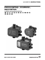
PRESSCONTROL
®
, ECOPRESS
®
,
MASCONTROL
®
GRUNDFOS INSTRUCTIONS
Installation and operating instructions

2
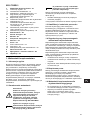
Declaration of Conformity
We, Grundfos, declare under our sole responsibility that the products
PRESSCONTROL
®
, ECOPRESS
®
and MASCONTROL
®
, to which this
declaration relates, are in conformity with these Council directives on
the approximation of the laws of the EC member states:
– Low Voltage Directive (2006/95/EC).
Standards used: EN 60730-1 and EN 60730-2-6.
– EMC Directive (2004/108/EC).
Standards used: EN 55014-1, EN 55014-2, EN 61000-3-2 and
EN 61000-3-3.
Konformitätserklärung
Wir, Grundfos, erklären in alleiniger Verantwortung, dass die Produkte
PRESSCONTROL
®
, ECOPRESS
®
und MASCONTROL
®
, auf die sich
diese Erklärung bezieht, mit den folgenden Richtlinien des Rates zur
Angleichung der Rechtsvorschriften der EU-Mitgliedsstaaten
übereinstimmen:
– Niederspannungsrichtlinie (2006/95/EG).
Normen, die verwendet wurden: EN 60730-1 und EN 60730-2-6.
– EMV-Richtlinie (2004/108/EG).
Normen, die verwendet wurden: EN 55014-1, EN 55014-2,
EN 61000-3-2 und EN 61000-3-3.
Déclaration de Conformité
Nous, Grundfos, déclarons sous notre seule responsabilité, que les
produits PRESSCONTROL
®
, ECOPRESS
®
et MASCONTROL
®
,
auxquels se réfère cette déclaration, sont conformes aux Directives du
Conseil concernant le rapprochement des législations des Etats
membres CE relatives aux normes énoncées ci-dessous :
– Directive Basse Tension (2006/95/CE).
Normes utilisées : EN 60730-1 et EN 60730-2-6.
– Directive Compatibilité Electromagnétique CEM (2004/108/CE).
Normes utilisées : EN 55014-1, EN 55014-2, EN 61000-3-2 et
EN 61000-3-3.
Dichiarazione di Conformità
Grundfos dichiara sotto la sua esclusiva responsabilità che i prodotti
PRESSCONTROL
®
, ECOPRESS
®
e MASCONTROL
®
, ai quali si
riferisce questa dichiarazione, sono conformi alle seguenti direttive del
Consiglio riguardanti il riavvicinamento delle legislazioni degli Stati
membri CE:
– Direttiva Bassa Tensione (2006/95/CE).
Norme applicate: EN 60730-1 e EN 60730-2-6.
– Direttiva EMC (2004/108/CE).
Norme applicate: EN 55014-1, EN 55014-2, EN 61000-3-2 e
EN 61000-3-3.
Declaración de Conformidad
Nosotros, Grundfos, declaramos bajo nuestra entera responsabilidad
que los productos PRESSCONTROL
®
, ECOPRESS
®
y
MASCONTROL
®
, a los cuales se refiere esta declaración, están
conformes con las Directivas del Consejo en la aproximación de las
leyes de las Estados Miembros del EM:
– Directiva de Baja Tensión (2006/95/CE).
Normas aplicadas: EN 60730-1 y EN 60730-2-6.
– Directiva EMC (2004/108/CE).
Normas aplicadas: EN 55014-1, EN 55014-2, EN 61000-3-2 y
EN 61000-3-3.
Declaração de Conformidade
A Grundfos declara sob sua única responsabilidade que os produtos
PRESSCONTROL
®
, ECOPRESS
®
e MASCONTROL
®
, aos quais diz
respeito esta declaração, estão em conformidade com as seguintes
Directivas do Conselho sobre a aproximação das legislações dos
Estados Membros da CE:
– Directiva Baixa Tensão (2006/95/CE).
Normas utilizadas: EN 60730-1 e EN 60730-2-6.
– Directiva EMC (compatibilidade electromagnética) (2004/108/CE).
Normas utilizadas: EN 55014-1, EN 55014-2, EN 61000-3-2 e
EN 61000-3-3.
Δήλωση Συμμόρφωσης
Εμείς, η Grundfos, δηλώνουμε με αποκλειστικά δική μας ευθύνη ότι τα
προϊόντα PRESSCONTROL
®
, ECOPRESS
®
και MASCONTROL
®
στα
οποία αναφέρεται η παρούσα δήλωση, συμμορφώνονται με τις εξής
Οδηγίες του Συμβουλίου περί προσέγγισης των νομοθεσιών των
κρατών μελών της ΕΕ:
– Οδηγία χαμηλής τάσης (2006/95/EC).
Πρότυπα που χρησιμοποιήθηκαν: EN 60730-1 και EN 60730-2-6.
– Οδηγία Ηλεκτρομαγνητικής Συμβατότητας (EMC) (2004/108/EC).
Πρότυπα που χρησιμοποιήθηκαν: EN 55014-1, EN 55014-2,
EN 61000-3-2 και EN 61000-3-3.
Overeenkomstigheidsverklaring
Wij, Grundfos, verklaren geheel onder eigen verantwoordelijkheid dat
de producten PRESSCONTROL
®
, ECOPRESS
®
en MASCONTROL
®
waarop deze verklaring betrekking heeft, in overeenstemming zijn met
de Richtlijnen van de Raad in zake de onderlinge aanpassing van de
wetgeving van de EG Lidstaten betreffende:
– Laagspannings Richtlijn (2006/95/EC).
Gebruikte normen: EN 60730-1 en EN 60730-2-6.
– EMC Richtlijn (2004/108/EC).
Gebruikte normen: EN 55014-1, EN 55014-2, EN 61000-3-2 en
EN 61000-3-3.
Försäkran om överensstämmelse
Vi, Grundfos, försäkrar under ansvar att produkterna PRESS-
CONTROL
®
, ECOPRESS
®
och MASCONTROL
®
, som omfattas av
denna försäkran, är i överensstämmelse med rådets direktiv om
inbördes närmande till EU-medlemsstaternas lagstiftning, avseende:
– Lågspänningsdirektivet (2006/95/EG).
Tillämpade standarder: EN 60730-1 och EN 60730-2-6.
– EMC-direktivet (2004/108/EG).
Tillämpade standarder: EN 55014-1, EN 55014-2, EN 61000-3-2 och
EN 61000-3-3.
Vaatimustenmukaisuusvakuutus
Me, Grundfos, vakuutamme omalla vastuullamme, että tuotteet
PRESSCONTROL
®
, ECOPRESS
®
ja MASCONTROL
®
, joita tämä
vakuutus koskee, ovat EY:n jäsenvaltioiden lainsäädännön
yhdenmukaistamiseen tähtäävien Euroopan neuvoston direktiivien
vaatimusten mukaisia seuraavasti:
– Pienjännitedirektiivi (2006/95/EY).
Sovellettavat standardit: EN 60730-1 ja EN 60730-2-6.
– EMC-direktiivi (2004/108/EY).
Sovellettavat standardit: EN 55014-1, EN 55014-2, EN 61000-3-2 ja
EN 61000-3-3.
Overensstemmelseserklæring
Vi, Grundfos, erklærer under ansvar at produkterne PRESSCONTROL
®
,
ECOPRESS
®
og MASCONTROL
®
som denne erklæring omhandler, er
i overensstemmelse med disse af Rådets direktiver om indbyrdes
tilnærmelse til EF-medlemsstaternes lovgivning:
– Lavspændingsdirektivet (2006/95/EF).
Anvendte standarder: EN 60730-1 og EN 60730-2-6.
– EMC-direktivet (2004/108/EF).
Anvendte standarder: EN 55014-1, EN 55014-2, EN 61000-3-2 og
EN 61000-3-3.
Deklaracja zgodności
My, Grundfos, oświadczamy z pełną odpowiedzialnością, że nasze
wyroby PRESSCONTROL
®
, ECOPRESS
®
oraz MASCONTROL
®
,
których deklaracja niniejsza dotyczy, są zgodne z następującymi
wytycznymi Rady d/s ujednolicenia przepisów prawnych krajów
członkowskich WE:
– Dyrektywa Niskonapięciowa (LVD) (2006/95/WE).
Zastosowane normy: EN 60730-1 oraz EN 60730-2-6.
– Dyrektywa EMC (2004/108/WE).
Zastosowane normy: EN 55014-1, EN 55014-2, EN 61000-3-2 oraz
EN 61000-3-3.

3
Декларация о соответствии
Мы, компания Grundfos, со всей ответственностью заявляем,
что изделия PRESSCONTROL
®
, ECOPRESS
®
и MASCONTROL
®
,
к которым относится настоящая декларация, соответствуют
следующим Директивам Совета Евросоюза об унификации
законодательных предписаний стран-членов ЕС:
– Низковольтное оборудование (2006/95/EC).
Применявшиеся стандарты: EN 60730-1 и EN 60730-2-6.
– Электромагнитная совместимость (2004/108/EC).
Применявшиеся стандарты: EN 55014-1, EN 55014-2,
EN 61000-3-2 и EN 61000-3-3.
Declaraţie de Conformitate
Noi, Grundfos, declarăm pe propria răspundere că produsele
PRESSCONTROL
®
, ECOPRESS
®
şi MASCONTROL
®
, la care se referă
această declaraţie, sunt în conformitate cu aceste Directive de Consiliu
asupra armonizării legilor Statelor Membre CE:
– Directiva Tensiune Joasă (2006/95/CE).
Standarde utilizate: EN 60730-1 şi EN 60730-2-6.
– Directiva EMC (2004/108/CE).
Standarde utilizate: EN 55014-1, EN 55014-2, EN 61000-3-2 şi
EN 61000-3-3.
Prohlášení o shodě
My firma Grundfos prohlašujeme na svou plnou odpovědnost, že
výrobky PRESSCONTROL
®
, ECOPRESS
®
a MASCONTROL
®
, na něž
se toto prohlášení vztahuje, jsou v souladu s ustanoveními směrnice
Rady pro sblížení právních předpisů členských států Evropského
společenství v oblastech:
–Směrnice pro nízkonapět’ové aplikace (2006/95/ES).
Použité normy: EN 60730-1 a EN 60730-2-6.
–Směrnice pro elektromagnetickou kompatibilitu (EMC)
(2004/108/ES).
Použité normy: EN 55014-1, EN 55014-2, EN 61000-3-2 a
EN 61000-3-3.
Prehlásenie o konformite
My firma Grundfos prehlasujeme na svoju plnú zodpovednost’, že
výrobky PRESSCONTROL
®
, ECOPRESS
®
a MASCONTROL
®
, na ktoré
sa toto prehlásenie vzt’ahuje, sú v súlade s ustanovením smernice Rady
pre zblíženie právnych predpisov členských štátov Európskeho
spoločenstva v oblastiach:
– Smernica pre nízkonapät’ové aplikácie (2006/95/EC).
Použité normy: EN 60730-1 a EN 60730-2-6.
– Smernica pre elektromagnetickú kompatibilitu (2004/108/EC).
Použité normy: EN 55014-1, EN 55014-2, EN 61000-3-2 a
EN 61000-3-3.
Bjerringbro, 15th February 2010
Jan Strandgaard
Technical Director

4

5
PRESSCONTROL
®
, ECOPRESS
®
,
MASCONTROL
®
Installation and operating instructions 6
Montage- und Betriebsanleitung 10
Notice d'installation et d'entretien 15
Istruzioni di installazione e funzionamento 19
Instrucciones de instalación y funcionamiento 23
Instruções de instalação e funcionamento 27
Οδηγίες εγκατάστασης και λειτουργίας 31
Installatie- en bedieningsinstructies 35
Monterings- och driftsinstruktion 39
Asennus- ja käyttöohjeet 43
Monterings- og driftsinstruktion 47
Instrukcja montażu i eksploatacji 51
Руководство по монтажу и эксплуатации 56
Instrucţiuni de instalare şi utilizare 63
Montážní a provozní návod 67
Návod na montáž a prevádzku 72

6
Original installation and operating instructions.
CONTENTS
1. Applications - 6
2. Control panels - 6
3. Installation - 6
4. Electrical connection - 7
5. Start-up - 7
6. Operation - 8
6.1 Normal operation - 8
6.2 Dry running - 8
6.3 Frost protection - 8
7. Technical data - 8
8. Fault finding chart - 9
9. Disposal - 9
These instructions apply to the units:
• PRESSCONTROL
®
, types PC 15 and 22
• ECOPRESS
®
, types EC 15 and 22
• MASCONTROL
®
, types MC 15 and 22.
1. Applications
The units, which incorporate dry-running protection,
are intended for mounting on Grundfos pumps.
They are used for automatic operation of pumps in
small water supply systems in single-family houses
and blocks of flats, for garden watering, etc.
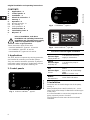
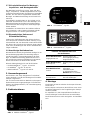
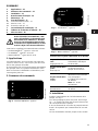
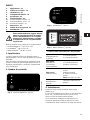
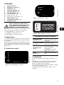
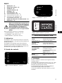
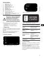
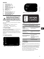
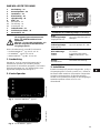
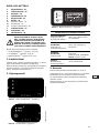
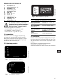
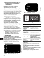
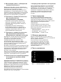
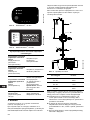
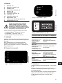
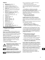
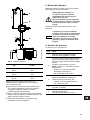
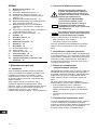
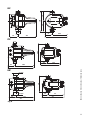
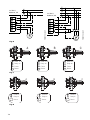
2. Control panels
Fig. 1 PRESSCONTROL
®
, type PC
Fig. 2 ECOPRESS
®
, type EC
Fig. 3 MASCONTROL
®
, type MC
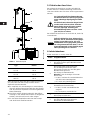
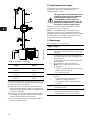
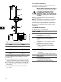
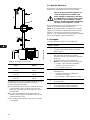
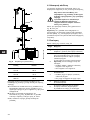
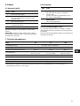
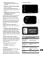
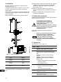
3. Installation
Install the unit on the discharge side of the pump,
see fig. 4.
When pumping from a well, borehole, etc., a non-
return valve must always be fitted to the suction pipe
of the pump.
It is recommended to connect the pump/unit to the
piping system by means of unions.
The installation location must be clean and well
ventilated.
Prior to installation, read these
installation and operating instructions.
Installation and operation must comply
with local regulations and accepted
codes of good practice.
TM03 0156 4304
TM03 0157 4304TM03 0205 4504
Function of indicator lights and button
Green
indicator light:
Supply/Power on
is on when the electricity
supply is switched on.
Yellow
indicator light:
On/Pump on
is on when the pump is
running.
Red
indicator light:
Failure
is on in case of operation
failure.
See section 8. Fault finding
chart.
Note: PC and MC only.
Button:
Reset/Restart
resets fault indications.
Power on
Pump on
Failure
Restart

7
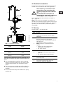
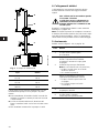
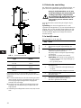
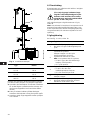
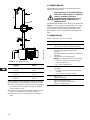
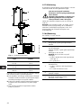
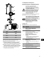
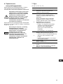
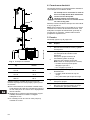
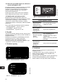
Fig. 4 Installation example
The unit can be fitted directly to the discharge port of
the pump or between the pump and the first draw-off
point.
A It is recommended to install the unit so that the
distance of height between the unit and the high-
est draw-off point does not exceed the values
stated.
B The arrows on the unit indicate the flow direction.
Always install the unit with the arrows pointing
upwards.
C Do not install draw-off points between the pump
and the unit.
4. Electrical connection
The electrical connections and protection must be
carried out in accordance with local regulations.
Carry out the electrical connection as shown in
fig. B, page 78.
Note: If the unit is incorporated in a system con-
nected to an electricity supply system, which is/can
be separated from the public supply, e.g. generator
operation, the unit should be protected against
overvoltage.
5. Start-up
See also figs. C and D, page 78.
TM00 5589 1195
Type H max.
PC 15
PC 22
15 m
22 m
EC 15
EC 22
8 m
10 m
MC 15
MC 22
15 m
22 m
A
B
C
H
Never make any connections in the
terminal box of the unit unless the
electricity supply has been switched
off.
The unit must be connected to an
external mains switch with a minimum
contact gap of 3 mm in all poles.
Step Action
1
Switch on the electricity supply.
The green and yellow indicator lights
illuminate.
2
The pump runs for a few seconds until
there is pressure on the system.
The pump stops and the yellow indicator
light goes out.
The system is ready for operation.
Note: If there is no pressure on the
system,
• PC/MC: the red indicator light
illuminates. Go to point 3.
• EC: go to point 3.
3
Open a tap and press Reset/Restart
• PC/MC: until the red indicator light
goes out.
• EC: until the water starts flowing.
4
Close the tap.
The pump stops.
5
The green indicator light illuminates.
The yellow indicator light goes out.
The unit is ready for operation.

8
6. Operation
6.1 Normal operation
In case of minor system leakages, the pump starts.
Note: In case of a supply failure, the pump restarts
automatically when the supply has been restored.
6.2 Dry running
6.3 Frost protection
If the unit is not being used during periods of frost,
the unit and the pipework must be drained.
The unit has no drain hole and has to be removed for
drainage.
7. Technical data
* The technical data may be limited by the pump data. See installation and operating instructions for
the pump.
Step Action
1 Open a tap.
2
The unit starts the pump.
The pump runs as long as water
is consumed.
3 Close the tap.
4
The unit stops the pump at maximum
pump pressure.
5 The unit is ready for operation.
Step Action
1
Dry running!
The unit stops the pump after approx.
10 seconds.
PC/MC: The red indicator light illuminates.
EC: No indicator light.
2
Water flow!
Press Reset/Restart.
3 The unit is ready for operation.
Data EC PC MC
Supply voltage 1 x 230 V ±10 %, 50/60 Hz
Ambient temperature +65 °C +65 °C +65 °C
Maximum liquid temperature +60 °C +65 °C +65 °C
Cut-in pressure*
EC 15: 1.5 bar
EC 22: 2.2 bar
PC 15: 1.5 bar
PC 22: 2.2 bar
MC 15: 1.5 bar
MC 22: 2.2 bar
Maximum system pressure 1 MPa (10 bar) 1 MPa (10 bar) 1 MPa (10 bar)
Contact load 6 A 8 A 16 A
Enclosure class IP 65 IP 65 IP 65
Dimensions See fig. A, page 77

9
8. Fault finding chart
9. Disposal
This product or parts of it must be disposed of in an
environmentally sound way:
1. Use the public or private waste collection service.
2. If this is not possible, contact the nearest
Grundfos company or service workshop.
Before starting work on the pump/unit, make sure that the electricity supply has been
switched off and that it cannot be accidentally switched on.
Fault Cause Remedy
1. The pump does
not start.
a) The fuses in the electric installation
are blown.
Replace the fuses. If the new ones blow
too, the electric installation should be
checked.
b) The ELCB or the voltage-operated
ELCB has tripped out.
Cut in the circuit breaker.
c) No electricity supply. Contact the electricity supply authorities.
d) The motor protection has cut off the
electricity supply due to overload.
Check whether the motor/pump is
blocked.
e) The pump is defective. Repair or replace the pump.
2. The green
indicator light is
on, but the pump
does not start
when water is
consumed.
a) Too high system pressure. Reduce the pressure.
b) Too big distance of height between
the unit and the draw-off point.
Adapt the installation.
3. Frequent starts
and stops.
a) Leakage in the pipework. Check and repair the pipework.
b) Non-return valve or foot valve
leaking.
Replace the non-return valve or foot
valve.
4. The pump does
not stop.
a) The pump is not capable of
delivering the required discharge
pressure.
Replace the pump.
b) The unit is defective. Replace the unit.
5. The red
indicator light
is on.
a) No water available at the pump
suction port.
Check the pipework.
b) The pump starts to self-prime
(jet pumps only).
See section 5. Start-up.
c) The pump or unit is defective. Replace the pump or unit.
Subject to alterations.

10
INHALTSVERZEICHNIS
1. Sicherheitshinweise - 10
1.1 Allgemeines - 10
1.2 Kennzeichnung von Hinweisen - 10
1.3 Personalqualifikation und -schulung - 10
1.4 Gefahren bei Nichtbeachtung der
Sicherheitshinweise - 10
1.5 Sicherheitsbewusstes Arbeiten - 10
1.6 Sicherheitshinweise für den Betreiber/
Bediener - 10
1.7 Sicherheitshinweise für Wartungs-,
Inspektions- und Montagearbeiten - 11
1.8 Eigenmächtiger Umbau und
Ersatzteilherstellung - 11
1.9 Unzulässige Betriebsweisen - 11
2. Verwendungszweck - 11
3. Bedientastaturen - 11
4. Montage - 11
5. Elektrischer Anschluss - 12
6. Inbetriebnahme - 12
7. Betrieb - 13
7.1 Normalbetrieb - 13
7.2 Trockenlauf - 13
7.3 Frostsicherung - 13
8. Technische Daten - 13
9. Störungsübersicht - 14
10. Entsorgung - 14
1. Sicherheitshinweise
1.1 Allgemeines
Diese Montage- und Betriebsanleitung enthält grund-
legende Hinweise, die bei Installation, Betrieb und
Wartung zu beachten sind. Sie ist daher unbedingt
vor Montage und Inbetriebnahme vom Monteur
sowie dem zuständigen Fachpersonal/Betreiber zu
lesen. Sie muss ständig am Einsatzort der Anlage
verfügbar sein.
Es sind nicht nur die unter diesem Abschnitt "Sicher-
heitshinweise" aufgeführten, allgemeinen Sicher-
heitshinweise zu beachten, sondern auch die unter
den anderen Abschnitten eingefügten, speziellen
Sicherheitshinweise.
1.2 Kennzeichnung von Hinweisen
Direkt an der Anlage angebrachte Hinweise müssen
unbedingt beachtet und in vollständig lesbarem
Zustand gehalten werden.
1.3 Personalqualifikation und -schulung
Das Personal für Bedienung, Wartung, Inspektion
und Montage muss die entsprechende Qualifikation
für diese Arbeiten aufweisen.
Verantwortungsbereich, Zuständigkeit und die Über-
wachung des Personals müssen durch den Betreiber
genau geregelt sein.
1.4 Gefahren bei Nichtbeachtung der
Sicherheitshinweise
Die Nichtbeachtung der Sicherheitshinweise kann
sowohl eine Gefährdung für Personen als auch für
die Umwelt und Anlage zur Folge haben. Die Nicht-
beachtung der Sicherheitshinweise kann zum Ver-
lust jeglicher Schadenersatzansprüche führen.
Im einzelnen kann Nichtbeachtung beispielsweise
folgende Gefährdungen nach sich ziehen:
• Versagen wichtiger Funktionen der Anlage
• Versagen vorgeschriebener Methoden zur
Wartung und Instandhaltung
• Gefährdung von Personen durch elektrische und
mechanische Einwirkungen.
1.5 Sicherheitsbewusstes Arbeiten
Die in dieser Montage- und Betriebsanleitung aufge-
führten Sicherheitshinweise, die bestehenden natio-
nalen Vorschriften zur Unfallverhütung sowie even-
tuelle interne Arbeits-, Betriebs- und Sicherheitsvor-
schriften des Betreibers, sind zu beachten.
1.6 Sicherheitshinweise für den
Betreiber/Bediener
Gefährdungen durch elektrische Energie sind aus-
zuschließen (Einzelheiten hierzu siehe z.B. in den
Vorschriften des VDE und der örtlichen Energiever-
sorgungsunternehmen).
Die in dieser Montage- und Betriebs-
anleitung enthaltenen Sicherheitshin-
weise, die bei Nichtbeachtung Gefähr-
dungen für Personen hervorrufen
können, sind mit allgemeinem
Gefahrensymbol "Sicherheitszeichen
nach DIN 4844-W00" besonders
gekennzeichnet.
Dieses Symbol finden Sie bei Sicher-
heitshinweisen, deren Nichtbeachtung
Gefahren für die Maschine und deren
Funktionen hervorrufen kann.
Hier stehen Ratschläge oder Hinweise,
die das Arbeiten erleichtern und für
einen sicheren Betrieb sorgen.
Achtung
Hinweis

11
1.7 Sicherheitshinweise für Wartungs-,
Inspektions- und Montagearbeiten
Der Betreiber hat dafür zu sorgen, dass alle War-
tungs-, Inspektions- und Montagearbeiten von auto-
risiertem und qualifiziertem Fachpersonal ausgeführt
werden, das sich durch eingehendes Studium der
Montage- und Betriebsanleitung ausreichend infor-
miert hat.
Grundsätzlich sind Arbeiten an der Anlage nur im
Stillstand durchzuführen. Die in der Montage- und
Betriebsanleitung beschriebene Vorgehensweise
zum Stillsetzen der Anlage muss unbedingt einge-
halten werden.
Unmittelbar nach Abschluss der Arbeiten müssen
alle Sicherheits- und Schutzeinrichtungen wieder
angebracht bzw. in Funktion gesetzt werden.
1.8 Eigenmächtiger Umbau und
Ersatzteilherstellung
Umbau oder Veränderungen der Anlage sind nur
nach Absprache mit dem Hersteller zulässig. Origi-
nalersatzteile und vom Hersteller autorisiertes Zube-
hör dienen der Sicherheit. Die Verwen-dung anderer
Teile kann die Haftung für die daraus entstehenden
Folgen aufheben.
1.9 Unzulässige Betriebsweisen
Die Betriebssicherheit der gelieferten Anlage ist nur
bei bestimmungsgemäßer Verwendung entspre-
chend Abschnitt 2. Verwendungszweck der Mon-
tage- und Betriebsanleitung gewährleistet. Die in
den technischen Daten angegebenen Grenzwerte
dürfen auf keinen Fall überschritten werden.
Diese Anleitung bezieht sich auf die Einheiten
• PRESSCONTROL
®
, Typ PC 15 und 22
• ECOPRESS
®
, Typ EC 15 und 22
• MASCONTROL
®
, Typ MC 15 und 22.
2. Verwendungszweck
Die Einheiten, die einen integrierten Trockenlauf-
schutz besitzen, sind für die Montage auf Grundfos
Pumpen vorgesehen.
Sie sind zum automatischen Betrieb von Pumpen in
kleinen Wasserversorgungsanlagen in Einfamilien-
häusern und Etagenhäusern, für Gartenberegnung
usw. geeignet.
3. Bedientastaturen
Abb. 1 PRESSCONTROL
®
, Typ PC
Abb. 2 ECOPRESS
®
, Typ EC
Abb. 3 MASCONTROL
®
, Typ MC
4. Montage
Die Einheit auf der Druckseite der Pumpe einbauen,
siehe Abb. 4.
Beim Pumpen aus Brunnen, Bohrlöchern usw. muss
ein Rückschlagventil in der Saugleitung der Pumpe
montiert werden.
Es empfiehlt sich, die Pumpe/Einheit mit Hilfe von
Verschraubungen an das Rohrnetz anzuschließen.
Der Einbauort muss trocken und gut be- und entlüftet
sein.
TM03 0156 4304
TM03 0157 4304TM03 0205 4504
Funktion der Meldeleuchten und
der Bedientaste
Grüne Meldeleuchte:
Supply/Power on
leuchtet, wenn die
Versorgungsspannung
eingeschaltet ist.
Gelbe Meldeleuchte:
On/Pump on
leuchtet, wenn die Pumpe
läuft.
Rote Meldeleuchte:
Failure
leuchtet bei Betriebs-
störungen.
Siehe Abschnitt
9. Störungsübersicht.
Hinweis: Nur PC und MC.
Taste:
Reset/Restart
Taste zur Quittierung
der Störmeldungen.
Power on
Pump on
Failure
Restart

12
Abb. 4 Einbaubeispiel
Die Einheit kann direkt auf den Pumpen-Druckstut-
zen oder zwischen der Pumpe und der ersten
Zapfstelle montiert werden.
A Es empfiehlt sich, die Montage so vorzunehmen,
dass der Höhenunterschied zwischen der Einheit
und der obersten Zapfstelle nicht die angeführten
Werte übersteigt.
B Die Pfeile auf der Einheit zeigen die Durchfluss-
richtung an. Die Einheit muss immer so eingebaut
werden, dass die Pfeile nach oben zeigen.
C Es darf keine Zapfstellen zwischen der Pumpe
und der Einheit installiert werden.
5. Elektrischer Anschluss
Der elektrische Anschluss und der erforderliche
Schutz müssen in Übereinstimmung mit den örtli-
chen Vorschriften des EVU bzw. VDE vorgenommen
werden.
Der elektrische Anschluss ist nach Abb. B, Seite 78,
vorzunehmen.
6. Inbetriebnahme
Siehe auch Abb. C und D, Seite 78.
TM00 5589 1195
Typ H max.
PC 15
PC 22
15 m
22 m
EC 15
EC 22
8 m
10 m
MC 15
MC 22
15 m
22 m
A
B
C
H
Vor jedem Eingriff im Klemmenkasten
der Einheit muss die Versorgungsspan-
nung unbedingt allpolig abgeschaltet
sein.
Die Einheit muss bauseits abgesichert
werden und sollte an einen externen
Netzschalter angeschlossen werden.
Auf eine allpolige Trennung mit
Kontaktöffnungsweite von min. 3 mm
(pro Pol) ist zu achten.
Falls die Einheit in einer Anlage einge-
baut ist, die an eine Stromversorgungs-
anlage angeschlossen ist, die vom
öffentlichen Versorgungsnetz getrennt
ist oder getrennt werden kann, z.B. bei
Generatorbetrieb, ist die Einheit gegen
Überspannungen zu schützen.
Stufe Vorgehensweise
1
Versorgungsspannung einschalten.
Die grüne und die gelbe Meldeleuchten
leuchten auf.
2
Die Pumpe läuft einige Sekunden,
bis die Anlage unter Druck steht.
Die Pumpe schaltet aus und die gelbe
Meldeleuchte geht aus.
Die Anlage ist betriebsbereit.
Hinweis: Falls die Anlage nicht unter
Druck steht,
• PC/MC: leuchtet die rote Meldeleuchte
auf. Mit Punkt 3 weitergehen.
• EC: mit Punkt 3 weitergehen.
3
Eine Zapfstelle öffnen und die
Reset/Restart-Taste drücken,
• PC/MC: bis die rote Meldeleuchte
ausgeht.
• EC: bis Wasser vorhanden ist.
4
Die Zapfstelle schließen.
Die Pumpe schaltet aus.
5
Die grüne Meldeleuchte leuchtet auf.
Die gelbe Meldeleuchte geht aus.
Die Einheit ist betriebsbereit.
Achtung

13
7. Betrieb
7.1 Normalbetrieb
Bei kleinen Systemlecks schaltet die Pumpe ein.
7.2 Trockenlauf
7.3 Frostsicherung
Falls in längeren Stillstandsperioden Frostgefahr
besteht, muss die Einheit sowie das Rohrsystem vor
der Außerbetriebnahme entleert werden.
Die Einheit hat keine Entleerungsmöglichkeit und
muss daher zur Entleerung demontiert werden.
8. Technische Daten
* Die technischen Daten können durch die Daten der Pumpe eingeschränkt sein. Siehe die Montage- und
Betriebsanleitung der Pumpe.
Stufe Vorgehensweise
1 Eine Zapfstelle öffnen.
2
Die Einheit schaltet die Pumpe ein.
Die Pumpe läuft, solange Wasser
verbraucht wird.
3 Die Zapfstelle schließen.
4
Die Einheit schaltet bei max.
Pumpendruck die Pumpe aus.
5 Die Einheit ist betriebsbereit.
Bei Stromausfall schaltet die Pumpe
automatisch wieder ein, sobald die
Stromversorgung wiederhergestellt ist.
Achtung
Stufe Vorgehensweise
1
Trockenlauf!
Die Einheit schaltet nach ca. 10 Sek.
die Pumpe aus.
PC/MC: Die rote Meldeleuchte
leuchtet auf.
EC: Keine Meldeleuchte.
2
Wasser vorhanden!
Reset/Restart-Taste drücken.
3 Die Einheit ist betriebsbereit.
Daten EC PC MC
Versorgungsspannung 1 x 230 V ±10 %, 50/60 Hz
Umgebungstemperatur +65 °C +65 °C +65 °C
Max. Medientemperatur +60 °C +65 °C +65 °C
Einschaltdruck*
EC 15: 1,5 bar
EC 22: 2,2 bar
PC 15: 1,5 bar
PC 22: 2,2 bar
MC 15: 1,5 bar
MC 22: 2,2 bar
Max. Systemdruck 1 MPa (10 bar) 1 MPa (10 bar) 1 MPa (10 bar)
Kontaktbelastung 6 A 8 A 16 A
Schutzart IP 65 IP 65 IP 65
Maße Siehe Abb. A, Seite 77

14
9. Störungsübersicht
10. Entsorgung
Dieses Produkt sowie Teile davon müssen
umweltgerecht entsorgt werden:
1. Benutzen Sie die öffentlichen oder privaten
Entsorgungsgesellschaften.
2. Ist das nicht möglich, wenden Sie sich bitte an
die nächste Grundfos Gesellschaft oder
Werkstatt.
Vor Beginn der Arbeit an der Pumpe/Einheit muss die Versorgungsspannung unbedingt
abgeschaltet werden. Es muss sichergestellt werden, dass die Versorgungsspannung nicht
versehentlich wieder eingeschaltet werden kann.
Störung Ursache Abhilfe
1. Die Pumpe läuft
nicht an.
a) Die Sicherungen der elektrischen
Installation sind durchgebrannt.
Sicherungen auswechseln. Brennen die
neuen Sicherungen auch durch, muss die
elektrische Installation überprüft werden.
b) Der Fehlerstrom- oder
Fehlerspannungsschutzschalter
hat ausgelöst.
Schutzschalter wieder einschalten.
c) Keine Versorgungsspannung. Mit dem Elektrizitäts-Versorgungsunter-
nehmen Verbindung aufnehmen.
d) Der Motorschutzschalter hat
wegen Überlast ausgelöst.
Prüfen, ob der Motor/die Pumpe
blockiert ist.
e) Pumpe defekt. Pumpe reparieren oder auswechseln.
2. Die grüne Meld-
eleuchte leuchtet,
aber die Pumpe
schaltet bei
Verbrauch nicht
ein.
a) Zu hoher Systemdruck. Druck reduzieren.
b) Zu großer Höhenunterschied
zwischen Einheit und Zapfstelle.
Installation anpassen.
3. Häufiges Ein- bzw.
Ausschalten.
a) Undichtigkeit in den
Rohrleitungen.
Rohrleitungen überprüfen und reparieren.
b) Rückschlagventil oder Fußventil
undicht.
Rückschlagventil oder Fußventil
auswechseln.
4. Die Pumpe
schaltet nicht aus.
a) Die Pumpe leistet nicht den
erforderlichen Förderdruck.
Pumpe auswechseln.
b) Einheit defekt. Einheit auswechseln.
5. Die rote Meld-
eleuchte leuchtet.
a) Kein Wasser am Pumpen-
Saugstutzen.
Rohrleitungen überprüfen.
b) Die Pumpe saugt selbst an
(nur Jetpumpen).
Siehe Abschnitt 6. Inbetriebnah me.
c) Pumpe oder Einheit defekt. Pumpe oder Einheit auswechseln.
Technische Änderungen vorbehalten.

15
SOMMAIRE
1. Applications - 15
2. Panneaux de commande - 15
3. Installation - 15
4. Branchement électrique - 16
5. Démarrage - 16
6. Fonctionnement - 17
6.1 Fonctionnement normal - 17
6.2 Marche à sec - 17
6.3 Protection anti-gel - 17
7. Caractéristiques techniques - 17
8. Tableau de recherche de défauts - 18
9. Mise au rebut - 18
Cette notice s'applique aux automatismes suivants :
• PRESSCONTROL
®
, types PC 15 et 22
• ECOPRESS
®
, types EC 15 et 22
• MASCONTROL
®
, types MC 15 et 22.
1. Applications
Ces automatismes, qui incorporent une protection
contre la marche à sec, sont conçus pour être mon-
tés sur des pompes Grundfos.
Ils sont utilisés pour un fonctionnement automatique
des pompes dans les systèmes d'adduction d'eau
dans les maisons individuelles et immeubles, pour
l'arrosage du jardin etc ...
2. Panneaux de commande
Fig. 1 PRESSCONTROL
®
, type PC
Fig. 2 ECOPRESS
®
, type EC
Fig. 3 MASCONTROL
®
, type MC
3. Installation
Installer l’automatisme du côté refoulement de la
pompe, voir fig. 4.
Lors d'un pompage à partir d'un puits, d'un forage
etc ... un clapet anti-retour doit toujours être monté
du côté aspiration de la pompe.
Il est recommandé de raccorder la pompe/l'automa-
tisme à la tuyauterie par l'intermédiaire de raccord-
unions.
Le site d'installation doit être propre et bien ventilé.
Avant d'installer l'automatisme, cette
notice d'installation et d'entretien doit
être étudiée avec attention. L'installa-
tion et le fonctionnement doivent être
conformes aux réglementations locales
et faire l'objet d'une bonne utilisation.
TM03 0156 4304
TM03 0157 4304TM03 0205 4504
Fonction des voyants d'indication et du bouton
Voyant d'indication
vert :
Supply/Power on
est allumé lorsque
l'alimentation électrique
est branchée.
Voyant d'indication
jaune :
On/Pump on
est allumé lorsque la
pompe est en service.
Voyant d'indication
rouge :
Failure
est allumé en cas de
défaut de fonctionnement.
Voir paragraphe
8. Tableau de recherche
de défauts.
Nota : PC et MC
uniquement.
Bouton:
Reset/Restart
réenclenche les indications
de défaut.
Power on
Pump on
Failure
Restart

16
Fig. 4 Exemple d'installation
L'automatisme peut être directement monté sur l'ori-
fice de refoulement de la pompe ou entre la pompe
et le premier point de soutirage.
A Il est recommandé de placer l’automatisme de
façon telle que la hauteur entre l’automatisme et
le point de soutirage le plus haut ne dépasse pas
les valeurs indiquées.
B Les flèches sur l’automatisme indiquent la direc-
tion du liquide. Toujours installer l’automatisme
avec les flèches pointant vers le haut.
C Ne pas installer les points de soutirage entre la
pompe et l'automatisme.
4. Branchement électrique
La protection et les branchements électriques
doivent être effectués conformément aux
réglementations locales.
Effectuer les branchements électriques comme
indiqué dans la fig. B, page 78.
Nota : Si l’automatisme est incorporé dans un
système connecté à une alimentation électrique
étant/pouvant être séparée du réseau public, comme
un générateur par exemple, l’automatisme devra
être protégé contre les surtensions.
5. Démarrage
Voir aussi figs. C et D, page 78.
TM00 5589 1195
Type H max.
PC 15
PC 22
15 m
22 m
EC 15
EC 22
8 m
10 m
MC 15
MC 22
15 m
22 m
A
B
C
H
Ne jamais faire de branchements dans
la boîte à bornes sans que l'alimenta-
tion électrique n'ait été coupée.
L’automatisme doit être relié à un
interrupteur général externe avec une
distance de séparation des contacts
d'au moins 3 mm sur chaque pôle.
Etape Action
1
Mettre sous tension.
Les voyants d'indication vert et jaune sont
allumés.
2
La pompe fonctionne pendant quelques
secondes jusqu'à ce que le système soit
sous pression.
La pompe s'arrête et le voyant d'indication
jaune s'éteint.
Le système est prêt à fonctionner.
Nota : S'il n'y a pas de pression dans
le système,
• PC/MC: le voyant d'indication rouge est
allumé. Aller au point 3.
• EC: aller au point 3.
3
Ouvrir un robinet et appuyer sur Reset/
Restart
• PC/MC: jusqu'à ce que le voyant
d'indication rouge s'éteigne.
• EC: jusqu'à ce que l'eau commence
à couler.
4
Fermer le robinet.
La pompe s'arrête.
5
Le voyant d'indication vert est allumé.
Le voyant d'indication jaune s'éteint.
L’automatisme est prêt à fonctionner.

17
6. Fonctionnement
6.1 Fonctionnement normal
En cas de petites fuites dans le système, la pompe
démarre.
Nota : En cas de défaut d'alimentation, la pompe
redémarre automatiquement lorsque l'alimentation
a été restaurée.
6.2 Marche à sec
6.3 Protection anti-gel
Si l'automatisme n'est pas utilisé pendant les
périodes de gel, il convient de le vidanger ainsi que
la tuyauterie.
L'automatisme ne dispose pas d'orifice de vidange et
doit être démonté pour une vidange.
7. Caractéristiques techniques
* Les caractéristiques techniques peuvent être limitées par les caractéristiques de la pompe. Voir la notice
d'installation et d'entretien de la pompe.
Etape Action
1 Ouvrir un robinet.
2
L'automatisme démarre la pompe.
La pompe fonctionne tant que l'eau est
consommée.
3 Fermer le robinet.
4
L'automatisme arrête la pompe à sa
pression maxi.
5 L'automatisme est prêt à fonctionner.
Etape Action
1
Marche à sec !
L'automatisme arrête la pompe après
10 secondes environ.
PC/MC: Le voyant d'indication rouge est
allumé.
EC: Pas de voyant d'indication.
2
Débit !
Appuyer sur Reset/Restart.
3 L'automatisme est prêt à fonctionner.
Caractéristiques EC PC MC
Tension d'alimentation 1 x 230 V ±10 %, 50/60 Hz
Température ambiante +65 °C +65 °C +65 °C
Température maxi du liquide +60 °C +65 °C +65 °C
Pression d'enclenchement*
EC 15: 1,5 bar
EC 22: 2,2 bar
PC 15: 1,5 bar
PC 22: 2,2 bar
MC 15: 1,5 bar
MC 22: 2,2 bar
Pression de service maxi 1 MPa (10 bar) 1 MPa (10 bar) 1 MPa (10 bar)
Charge du contact 6 A 8 A 16 A
Indice de protection IP 65 IP 65 IP 65
Dimensions Voir fig. A, page 77

18
8. Tableau de recherche de défauts
9. Mise au rebut
Ce produit ou des parties de celui-ci doit être mis au
rebut tout en préservant l'environnement :
1. Utiliser le service local public ou privé de collecte
des déchets.
2. Si ce n'est pas possible, envoyer ce produit à
Grundfos ou au réparateur agréé Grundfos le
plus proche.
Avant toute intervention sur la pompe et l'automatisme, s'assurer que l'alimentation
électrique a été coupée et qu'elle ne risque pas d'être branchée accidentellement.
Défaut Cause Remède
1. La pompe ne
fonctionne pas.
a) Les fusibles de l'installation
électrique ont sauté.
Remplacer les fusibles. Si les nouveaux
fusibles sautent, vérifier l'installation
électrique.
b) Le disjoncteur différentiel ou
le coupe-circuit sont déclenchés.
Réenclencher le coupe-circuit.
c) Pas d'électricité. Contacter l'EDF.
d) La protection moteur a coupé
l'alimentation électrique à cause
d'une surcharge.
Vérifier si le moteur ou la pompe est
bloqué.
e) La pompe est défectueuse. Réparer ou remplacer la pompe.
2. Le voyant
d'indication vert
est allumé, mais la
pompe ne démarre
pas lorsque l'eau
est consommée.
a) Pression trop élevée dans
le système.
Diminuer la pression.
b) Distance trop grande entre
l'automatisme et le point de
soutirage.
Revoir et adapter l'installation.
3. Nombre de
démarrages/arrêts
trop fréquents.
a) Fuite de la tuyauterie. Contrôler et réparer la tuyauterie.
b) Le clapet de pied/anti-retour fuit. Remplacer le clapet de pied/anti-retour.
4. La pompe ne
s'arrête pas.
a) La pompe n'est pas capable de
fournir la pression de refoulement
requise.
Remplacer la pompe.
b) L'automatisme est défectueux. Remplacer l'automatisme.
5. Le voyant
d'indication rouge
est allumé.
a) Pas d'eau disponible à l'orifice
d'aspiration de la pompe.
Vérifier la tuyauterie.
b) La pompe commence à s'auto-
amorcer (pompes auto-amorçantes
uniquement).
Voir paragraphe 5. Démarrage.
c) La pompe ou l'automatisme est
défectueux.
Remplacer la pompe ou l'automatisme.
Nous nous réservons tout droit de modifications.

19
INDICE
1. Applicazioni - 19
2. Quadro di controllo - 19
3. Installazione - 19
4. Collegamenti elettrici - 20
5. Avviamento - 20
6. Funzionamento - 21
6.1 Funzionamento normale - 21
6.2 Funzionamento a secco - 21
6.3 Protezione antigelo - 21
7. Dati tecnici - 21
8. Tabella di ricerca guasti - 22
9. Smaltimento - 22
Queste istruzioni sono valide per le seguenti unità:
• PRESSCONTROL
®
, tipi PC 15 e 22
• ECOPRESS
®
, tipi EC 15 e 22
• MASCONTROL
®
, tipi MC 15 e 22.
1. Applicazioni
Le unità, dotate di protezione integrata contro il
funzionamento a secco, sono da installare su pompe
Grundfos.
Sono usate per il funzionamento automatico delle
pompe in sistemi di approvvigionamento idrico di
abitazioni monofamiliari, condomini, appartamenti
e per l'irrigazione.
2. Quadro di controllo
Fig. 1 PRESSCONTROL
®
, tipo PC
Fig. 2 ECOPRESS
®
, tipo EC
Fig. 3 MASCONTROL
®
, tipo MC
3. Installazione
Installare l'unità sul lato mandata della pompa,
vedere fig. 4.
In caso di pompaggio da un pozzo, un foro di trivella-
zione, etc., occorre montare una valvola di non
ritorno sul lato aspirazione della pompa.
Si raccomanda di collegare la pompa/l'unità al
sistema di tubazioni tramite gli appositi raccordi.
L'installazione deve avvenire in un luogo ben areato.
Prima dell'installazione leggere attenta-
mente le presenti istruzioni di installa-
zione e funzionamento. Per il corretto
montaggio e funzionamento, rispettare
le disposizioni locali e la pratica della
regola d'arte.
TM03 0156 4304
TM03 0157 4304TM03 0205 4504
Funzione delle spie luminose e del pulsante
Spia verde:
Supply/Power on
(corrente)
si accende quando
la corrente è inserita.
Spia gialla:
On/Pump on
(accensione/
funzionamento)
si accende quando la
pompa è in funzione.
Spia rossa:
Failure (avaria)
si accende in caso di
avaria.
Vedere paragrafo
8. Tabella di ricerca
guasti.
Nota: Solo per PC e MC.
Pulsante:
Reset/Restart
(riavvio)
cancella le indicazioni di
guasto.
Power on
Pump on
Failure
Restart

20
Fig. 4 Esempio di installazione
L'unità deve essere montata direttamente sul lato
mandata della pompa o fra la pompa e la prima
utenza.
A Raccomandiamo di installare l'unità in modo che
l'altezza fra l'unità e l'utenza più alta non ecceda
i valori stabiliti.
B Le frecce sull'unità indicano la direzione del
flusso. Installare l'unità con le frecce rivolte verso
l'alto.
C Non installate le utenze fra la pompa e l'unità.
4. Collegamenti elettrici
I collegamenti e le protezioni elettriche devono
essere realizzati in base alle leggi localmente
vigenti.
Eseguire il collegamento elettrico come mostrato
nella fig. B, a pagina 78.
Nota: Se l'unità fa parte di un complesso connesso
al sistema di fornitura elettrica che può essere sepa-
rato dalla fornitura pubblica, ad es. un generatore,
l'unità deve essere protetta contro il sovravoltaggio.
5. Avviamento
Vedere anche le figure C e D, a pagina 78.
TM00 5589 1195
Tipo H max.
PC 15
PC 22
15 m
22 m
EC 15
EC 22
8 m
10 m
MC 15
MC 22
15 m
22 m
A
B
C
H
Non cablare mai la morsettiera quando
la corrente è inserita.
L'unità deve essere collegata ad un
interruttore di rete esterno con una
distanza minima fra i contatti di 3 mm
su tutti i poli.
Fase Azione
1
Inserire l'alimentazione elettrica.
La spia verde e quella gialla
si accendono.
2
La pompa funziona per pochi secondi
finchè c'è pressione nel sistema.
La pompa si arresta e la spia gialla
si spegne.
Il sistema è pronto per funzionare.
Nota: Se nel sistema non c'è pressione,
• PC/MC: la spia rossa si accende.
Andare al punto 3.
• EC: andare al punto 3.
3
Aprire un rubinetto e schiacciare
il pulsante Reset/Restart (riavvio)
• PC/MC: finchè la spia rossa non
si spegne.
• EC: finchè l'acqua non inizia
a scendere.
4
Chiudere il rubinetto.
La pompa si arresta.
5
La spia verde si accende.
La spia gialla si spegne.
L'unità è pronta per funzionare.
Pagina se încarcă...
Pagina se încarcă...
Pagina se încarcă...
Pagina se încarcă...
Pagina se încarcă...
Pagina se încarcă...
Pagina se încarcă...
Pagina se încarcă...
Pagina se încarcă...
Pagina se încarcă...
Pagina se încarcă...
Pagina se încarcă...
Pagina se încarcă...
Pagina se încarcă...
Pagina se încarcă...
Pagina se încarcă...
Pagina se încarcă...
Pagina se încarcă...
Pagina se încarcă...
Pagina se încarcă...
Pagina se încarcă...
Pagina se încarcă...
Pagina se încarcă...
Pagina se încarcă...
Pagina se încarcă...
Pagina se încarcă...
Pagina se încarcă...
Pagina se încarcă...
Pagina se încarcă...
Pagina se încarcă...
Pagina se încarcă...
Pagina se încarcă...
Pagina se încarcă...
Pagina se încarcă...
Pagina se încarcă...
Pagina se încarcă...
Pagina se încarcă...
Pagina se încarcă...
Pagina se încarcă...
Pagina se încarcă...
Pagina se încarcă...
Pagina se încarcă...
Pagina se încarcă...
Pagina se încarcă...
Pagina se încarcă...
Pagina se încarcă...
Pagina se încarcă...
Pagina se încarcă...
Pagina se încarcă...
Pagina se încarcă...
Pagina se încarcă...
Pagina se încarcă...
Pagina se încarcă...
Pagina se încarcă...
Pagina se încarcă...
Pagina se încarcă...
Pagina se încarcă...
Pagina se încarcă...
Pagina se încarcă...
Pagina se încarcă...
-
 1
1
-
 2
2
-
 3
3
-
 4
4
-
 5
5
-
 6
6
-
 7
7
-
 8
8
-
 9
9
-
 10
10
-
 11
11
-
 12
12
-
 13
13
-
 14
14
-
 15
15
-
 16
16
-
 17
17
-
 18
18
-
 19
19
-
 20
20
-
 21
21
-
 22
22
-
 23
23
-
 24
24
-
 25
25
-
 26
26
-
 27
27
-
 28
28
-
 29
29
-
 30
30
-
 31
31
-
 32
32
-
 33
33
-
 34
34
-
 35
35
-
 36
36
-
 37
37
-
 38
38
-
 39
39
-
 40
40
-
 41
41
-
 42
42
-
 43
43
-
 44
44
-
 45
45
-
 46
46
-
 47
47
-
 48
48
-
 49
49
-
 50
50
-
 51
51
-
 52
52
-
 53
53
-
 54
54
-
 55
55
-
 56
56
-
 57
57
-
 58
58
-
 59
59
-
 60
60
-
 61
61
-
 62
62
-
 63
63
-
 64
64
-
 65
65
-
 66
66
-
 67
67
-
 68
68
-
 69
69
-
 70
70
-
 71
71
-
 72
72
-
 73
73
-
 74
74
-
 75
75
-
 76
76
-
 77
77
-
 78
78
-
 79
79
-
 80
80


Grundfos MC 22 Installation And Operating Instructions Manual
- Tip
- Installation And Operating Instructions Manual
- Acest manual este potrivit și pentru
în alte limbi
- slovenčina: Grundfos MC 22
Lucrări înrudite
-
Grundfos PM 1 Installation And Operating Instructions Manual
-
-
-
-
-
-
Grundfos APG Series Installation And Operating Instructions Manual
-
-
Grundfos CMB-SP Booster PM2 Instructions Manual