Graphite 59G261 Manualul proprietarului
- Categorie
- Accesorii mixer / robot de bucătărie
- Tip
- Manualul proprietarului

SZLIFIERKA DO GIPSU
DRYWALL SANDER
GIPSSCHLEIFER
FALCSISZOLÓ
POLIZOR PENTRU PERETI GHIPSCARTON
BRUSKA NA SÁDRU
BRÚSKA NA SADRU
BRUSILNIK ZA GIPS
ŠLIFUOKLIS GIPSUI
SLĪPMAŠĪNA SIENU UN GRIESTU SLĪPĒŠANAI
KIPSILIHVIJA
BRUSILICA ZA GIPS
BRUSILICA ZA GIPS
ΛΕΙΑΝΤΉΡΑΣ ΓΙΑ ΤΟΊΧΟΥΣ ΚΑΙ ΤΑΒΆΝΙΑ
ES AMOLADORA PARA YESO
LEVIGATRICE PER CARTONGESSO
FR PONCEUSE À PLÂTRE
59G261
G.0122
* Części zamienne do tego produktu kupisz w gtxservice.pl przez min. 10 lat od jego zakupu.
Sklep gtxservice.pl realizuje min. 95% zamówień w skali roku.


3
INSTRUKCJA OBSŁUGI . . . . . . . . . . . . . . . . . . 6
INSTRUCTION MANUAL . . . . . . . . . . . . . . . . 13
BETRIEBSANLEITUNG. . . . . . . . . . . . . . . . . . 18
. . . . . . . 23
. . . . . . . . . . . . 29
HASZNÁLATI UTASÍTÁS. . . . . . . . . . . . . . . . . 34
INSTRUCTIUNI DE DESERVIRE . . . . . . . . . . . . 39
INSTRUKCE K OBSLUZE. . . . . . . . . . . . . . . . . 44
NÁVOD NA OBSLUHU . . . . . . . . . . . . . . . . . . 49
NAVODILA ZA UPORABO . . . . . . . . . . . . . . . 54
APTARNAVIMO INSTRUKCIJA. . . . . . . . . . . . . 59
LIETOŠANAS INSTRUKCIJA . . . . . . . . . . . . . . 64
KASUTUSJUHEND . . . . . . . . . . . . . . . . . . . . 69
. . . . . . . . . . 74
UPUTE ZA UPOTREBU. . . . . . . . . . . . . . . . . . 79
UPUTSTVO ZA UPOTREBU . . . . . . . . . . . . . . 84
ΟΗΓΙΕΣ ΧΡΗΣΗΣ . . . . . . . . . . . . . . . . . . . . 89
INSTRUCCIONES DE USO. . . . . . . . . . . . . . . . 94
MANUALE PER L’USO . . . . . . . . . . . . . . . . . . 99
MANUEL D’INSTRUCTION . . . . . . . . . . . . . . 104
ES
FR

4
1
3
4
9
8
11
10
5
5
7
6
2

5
A
8
7
8
16
GH
8
7
F
3
2
3
C
12
5
D
5
12
E
4
1
511 10
B
2

6
INSTRUKCJA ORYGINALNA OBSŁUGI
SZLIFIERKA DO GIPSU
59G261
UWAGA: PRZED PRZYSTĄPIENIEM DO UŻYTKOWANIA ELEKTRONARZĘDZIA NALEŻY UWAŻNIE PRZECZYTAĆ
NINIEJSZĄ INSTRUKCJĘ I ZACHOWAĆ JĄ DO DALSZEGO WYKORZYSTANIA.
SZCZEGÓŁOWE PRZEPISY BEZPIECZEŃSTWA
●Przed podłączeniem szlierki do sieci zawsze należy upewnić się czy napięcie sieci jest zgodne z
napięciem podanym na tabliczce znamionowej urządzenia.
●Szlierkę do gipsu wolno podłączać tylko do instalacji elektrycznej wyposażonej w zabezpieczenie
różnicowo prądowe, które przerwie zasilanie, jeżeli prąd upływu przekroczy 30mA w czasie krótszym
niż 30ms.
●Do szlierki należy podłączyć instalację odciągającą pył.
●Przed włączeniem szlierki należy upewnić się czy papier ścierny jest umocowany pewnie do tarczy
roboczej i czy nie dotyka do materiału, który ma być obrabiany.
●W czasie pracy należy pewnie trzymać szlierkę.
●Nie wolno dotykać części szlierki, które są w ruchu.
●Należy stosować przeciwpyłową maskę ochronną oraz przylegające do twarzy okulary ochronne. Pył
powstający podczas szlifowania powierzchni gipsowych jest szkodliwy dla zdrowia.
●Osoby postronne nie powinny wchodzić do pomieszczenia, w którym za pomocą szlierki szlifowany jest
gips. Nie powinno się również w takim pomieszczeniu jeść lub pić.
●Szlierką nie wolno pracować na mokro.
●Przewód zasilający urządzenia zawsze należy trzymać z dala od ruchomych części szlierki.
●Jeśli przewód zasilający podczas pracy uszkodzi się, odłącz bezzwłocznie zasilanie. NIE DOTYKAĆ
PRZEWODU PRZED ODŁĄCZENIEM ZASILANIA.
●OSTRZEŻENIE. Po wyłączeniu silnika tarcza robocza jeszcze się obraca.
●Utrzymuj rozciągnięty przewód zasilający z dala od tarczy roboczej.
●Nie pozwalaj obsługiwać szlierki dzieciom oraz osobom nie zapoznanym z instrukcją obsługi.
●PAMIĘTAJ. Operator lub użytkownik jest odpowiedzialny za wypadki lub występujące zagrożenia wobec
innych osób lub otoczenia.
●Wyciągnij wtyczkę z gniazda sieciowego:
- za każdym razem gdy odchodzisz od urządzenia;
- przed sprawdzeniem, czyszczeniem lub naprawą urządzenia;
●Naprawy szlierki powinny dokonywać tylko osoby uprawnione.
●Należy stosować tylko zalecane przez wytwórcę części zamienne.
KONSERWACJA I PRZECHOWYWANIE
●Utrzymywać w należytym stanie wszystkie podzespoły, aby być pewnym, że szlierka będzie bezpiecznie
pracować.
●Wymieniać w celu zachowania bezpieczeństwa zużyte lub uszkodzone części.
●Chronić szlierkę przed wilgocią.
●Przechowywać poza zasięgiem dzieci.
●Stosować papier ścierny właściwego typu.
UWAGA! Urządzenie służy do pracy wewnątrz pomieszczeń.
Mimo zastosowania konstrukcji bezpiecznej z samego założenia, stosowania środków
zabezpieczających i dodatkowych środków ochronnych, zawsze istnieje ryzyko szczątkowe doznania
urazów podczas pracy.

7
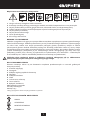
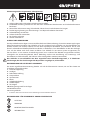
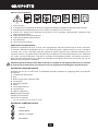
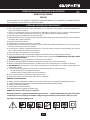
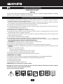
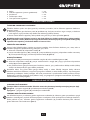
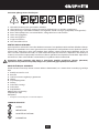
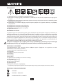
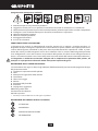
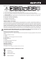
Objaśnienie zastosowanych piktogramów
1. Uwaga zachowaj szczególne środki ostrożności
2. Przeczytaj instrukcję obsługi, przestrzegaj ostrzeżeń i warunków bezpieczeństwa w niej zawartych!
3. Używaj środki ochrony osobistej (gogle ochronne, ochronniki słuchu, maskę przeciwpyłową)
4. Odłącz przewód zasilający przed rozpoczęciem czynności obsługowych lub naprawczych.
5. Używaj odzieży ochronnej
6. Używaj obuwia ochronnego
7. Chroń przed wilgocią
8. Klasa druga ochronności
BUDOWA I ZASTOSOWANIE
Szlierka wysięgnikowa do gipsu jest ręcznym elektronarzędziem napędzanym za pomocą jednofazowego
silnika komutatorowego. Szlierka przeznaczona jest do powierzchniowego szlifowania wykańczającego
na sucho ścian, sutów oraz innych powierzchni pokrytych gładzią szpachlową. Uchylna w dwóch
płaszczyznach głowica szlierki doskonale przylega do dowolnej powierzchni sutu czy ściany. Dzięki
wysięgnikowi można prowadzić pracę bez konieczności stosowania drabiny. Konstrukcja szlierki posiada
system umożliwiający podłączenie jej do zewnętrznego układu odciągającego pył, który musi być
podłączony podczas pracy. Obszary jej użytkowania to wykonawstwo prac remontowo – budowlanych
oraz wszelkich prac z zakresu samodzielnej działalności amatorskiej (majsterkowanie).
Szlierkę należy użytkować jedynie z podłączoną instalacją odciągającą pył np. odkurzaczem
przemysłowym przystosowanym do odciągania pyłu gipsowego.
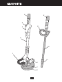
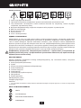
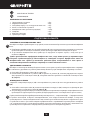
OPIS STRON GRAFICZNYCH
Poniższa numeracja odnosi się do elementów urządzenia przedstawionych na stronach gracznych
niniejszej instrukcji.
1. Przewód odpylający
2. Wysięgnik
3. Pokrętło regulacji prędkości obrotowej
4. Włącznik
5. Nakrętka zaciskowa
6. Silnik
7. Osłona tarczy roboczej
8. Tarcza robocza
9. Rękojeść dodatkowa
10. Przedłużka wysięgnika
11. Tuleja redukcyjna
12. Wąż ssący
* Mogą występować różnice między rysunkiem a wyrobem.
OPIS UŻYTYCH ZNAKÓW GRAFICZNYCH
UWAGA
OSTRZEŻENIE
MONTAŻ/USTAWIENIA
INFORMACJA

8
WYPOSAŻENIE I AKCESORIA
1. Przedłużka wysięgnika - 1 szt.
2. Tuleje redukcyjne - 3 szt.
3. Wąż ssący 1,2 m po rozciągnięciu 4 m - 1 szt.
4. Pas naramienny - 1 szt.
5. Papier ścierny (różna gradacja) - 14 szt.
6. Wkrętak - 1 szt.
7. Klucz sześciokątny - 1 szt.
8. Torba transportowa - 1 szt.
PRZYGOTOWANIE DO PRACY
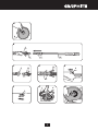
MOCOWANIE PAPIERU ŚCIERNEGO
Szlierka posiada tarczę roboczą z tzw. rzepem, co pozwala na łatwą i szybką wymianę papieru ściernego.
●Zbliżyć papier ścierny do tarczy robocze (8) tak, aby jego otwory pokrywały się z otworami w tarczy
roboczej szlierki i docisnąć, co zapewni skuteczne odprowadzanie pyłu.
●Aby zdjąć papier ścierny należy odchylić go z jednej strony, a następnie pociągnąć (rys. A).
Należy stosować perforowany papier ścierny, aby pył mógł docierać poprzez otwory w tarczy
roboczej do instalacji odprowadzającej pył. Przed każdorazową zmianą papieru ściernego należy
oczyścić tarczę roboczą usuwając z niej kurz i wszelkie zanieczyszczenia za pomocą np. szczotki lub
pędzelka.
PRZEDŁUŻANIE WYSIĘGNIKA
Szlierka do gipsu może być użytkowana z krótkim wysięgnikiem do pracy przy szlifowaniu np. ścian lub z
wykorzystaniem przedłużki wysięgnika zwiększającej zasięg podczas szlifowania np. sutów.
●Poluzować nakrętkę blokującą (5) wysięgnika (2).
●Umieścić przedłużkę wysięgnikową (10) w rurze wysięgnika (2), wsunąć tuleję redukcyjną (11)
w mocowanie nakrętki zaciskowej (5), ustawić pożądaną długość i dokręcić nakrętkę zaciskową (5)
(rys. B).
ODPROWDZANIE PYŁU
Zamocować wąż ssący (12) do końcówki wysięgnika (2) lub przedłużki wysięgnikowej (10).
●Poluzować nakrętkę zaciskową (5), wsunąć końcówkę węża ssącego (12) w otwór i zabezpieczyć
dokręcając nakrętkę zaciskową (5) (rys. C, D).
●Podłączyć drugi koniec węża ssącego do układu odsysającego np. odkurzacza warsztatowego (odkurzacz
musi być przystosowany do odsysania pyłu z gipsu).
Rozpoczynając pracę należy uruchomić odkurzacz a następnie szlierkę. Po zakończeniu pracy należy
postępować w sposób odwrotny najpierw wyłączyć szlierkę a później odkurzacz. Takie postępowanie
pozwoli uniknąć niepotrzebnego zapylenia w miejscu pracy. W niektórych modelach odkurzaczy
warsztatowych lub przemysłowych posiadających gniazdo zasilające dla elektronarzędzi następuje
automatyczne włączenie i wyłączenie odkurzacza sterowane włącznikiem elektronarzędzia.
PRACA / USTAWIENIA
WŁĄCZANIE / WYŁĄCZANIE
Napięcie sieci musi odpowiadać wielkości napięcia podanego na tabliczce znamionowej szlierki.
Włączanie - przełączyć przycisk włącznika (4) w poz I (rys. E).
Wyłączanie - przełączyć przycisk włącznika (4) w poz O.
REGULACJA PRĘDKOŚCI OBROTOWEJ
Na korpusie szlierki znajduje się pokrętło regulacji prędkości obrotowej (3). Prędkość obrotową dobiera się
w zależności od potrzeb (zależnie od zastosowanego papieru ściernego, twardości obrabianego materiału,
rodzaju pracy itp.). Obrót pokrętła regulacji prędkości obrotowej (3) zwiększa lub zmniejsza obroty tarczy
roboczej (rys. F).

9
PRACA SZLIFIERKĄ
Obrabiane powierzchnie powinny być suche bez ciał obcych jak np. śruby, gwoździe, wkręty itp.
Szlierkę należy trzymać pewnie, obiema rękami.
●Włączyć szlierkę i odczekać, aż tarcza robocza osiągnie maksymalną prędkość obrotową.
●Przyłożyć całą powierzchnię tarczy roboczej do powierzchni obrabianej (przegubowo zamocowana
tarcza robocza i jej osłona samoczynnie dopasują się do powierzchni) (rys. G).
●Wywierając umiarkowany nacisk przesuwać szlierkę po powierzchni obrabianej ruchami okrężnymi lub
przemiennie w kierunku poprzecznym i wzdłużnym.
●Nadmierny nacisk nie prowadzi do zwiększenia wydajności szlifowania, lecz może być przyczyną
szybszego zużycia elementów szlierki i papieru ściernego.
●Odsunięcie tarczy roboczej podczas pracy od powierzchni szlifowanej spowoduje wydostanie się pyłu
na zewnątrz urządzenia a tym samym do pomieszczenia, w którym odbywa się praca.
●Wydajność i jakość powierzchni szlifowanej w dużej mierze zależy od rodzaju zastosowanego papieru
ściernego i siły docisku. Rodzaj papieru ściernego najlepiej dobierać drogą prób.
●Kończąc szlifowanie zmniejszyć nacisk na szlierkę, wyłączyć silnik i odkurzacz.
●Wymieniać papier ścierny w momencie zaobserwowania jego zużycia.
●Stosować okresowe przerwy w pracy.
Nie należy uruchamiać szlierki, jeśli jej tarcza robocza jest oparta o powierzchnię obrabianą.
OBSŁUGA I KONSERWACJA
Przed przystąpieniem do jakichkolwiek czynności regulacyjnych, obsługowych lub naprawczych
należy urządzenie odłączyć od sieci zasilającej.
●Szlierkę należy zawsze utrzymywać w czystości.
●Do czyszczenia nie należy stosować wody lub innych cieczy.
●Szlierkę czyści się za pomocą szczotki.
●Regularnie należy czyścić szczeliny wentylacyjne, aby nie dopuścić do przegrzania silnika szlierki.
●W przypadku występowania nadmiernego iskrzenia na komutatorze sprawdzić stan szczotek węglowych
silnika.
●Szlierkę zawsze należy przechowywać w miejscu suchym, niedostępnym dla dzieci.
WYMIANA TARCZY ROBOCZEJ
Zużyta lub uszkodzona tarcza robocza powinna być bezzwłocznie wymieniona.
●Poluzować i odkręcić śrubę mocującą tarczę roboczą (8) (rys. H).
●Wymienić tarczę roboczą na nową, zamocować śrubą.
WYMIANA SZCZOTEK WĘGLOWYCH
Zużyte (krótsze niż 5 mm), spalone lub pęknięte szczotki węglowe silnika należy natychmiast
wymienić. Zawsze dokonuje się jednocześnie wymiany obu szczotek węglowych.
Czynność wymiany szczotek węglowych należy powierzyć wyłącznie osobie wykwalikowanej
wykorzystując części oryginalne.
Wszelkiego rodzaju usterki powinny być usuwane przez autoryzowany serwis producenta.
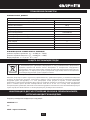
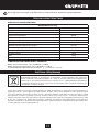
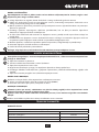
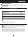
PARAMETRY TECHNICZNE
DANE ZNAMIONOWE
Szlierka do gipsu
Parametr Wartość
Napięcie zasilania 230 V AC
Częstotliwość zasilania 50 Hz
Moc znamionowa 600 W
Zakres prędkości obrotowej bez obciążenia 600-1500 min-1

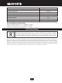
10
Zakres długości szlierki 1100-2000 mm
Średnica tarczy roboczej 225 mm
Średnica papieru ściernego 225 mm
Gwint wrzeciona M6
Klasa ochronności II
Stopień ochrony IP20
Masa 5,5 kg
Rok produkcji 2022
DANE DOTYCZĄCE HAŁASU I DRGAŃ
Poziom ciśnienia akustycznego : LpA = 85 dB(A) K = 3 dB(A)
Poziom mocy akustycznej : LwA = 96 dB(A) K = 3 dB(A)
Wartość ważona przyspieszenia drgań : ah = 3,18 m/s2 K = 1,5 m/s2
OCHRONA ŚRODOWISKA
Produktów zasilanych elektrycznie nie należy wyrzucać wraz z domowymi odpadkami, lecz oddać je
do utylizacji w odpowiednich zakładach. Informacji na temat utylizacji udzieli sprzedawca produktu
lub miejscowe władze. Zużyty sprzęt elektryczny i elektroniczny zawiera substancje nieobojętne
dla środowiska naturalnego. Sprzęt nie poddany recyclingowi stanowi potencjalne zagrożenie dla
środowiska i zdrowia ludzi.
* Zastrzega się prawo dokonywania zmian.
„Grupa Topex Spółka z ograniczoną odpowiedzialnością” Spółka komandytowa z siedzibą w Warszawie, ul. Pograniczna
2/4 (dalej: „Grupa Topex”) informuje, iż wszelkie prawa autorskie do treści niniejszej instrukcji (dalej: „Instrukcja”), w tym
m.in. jej tekstu, zamieszczonych fotograi, schematów, rysunków, a także jej kompozycji, należą wyłącznie do Grupy Topex
i podlegają ochronie prawnej zgodnie z ustawą z dnia 4 lutego 1994 roku, o prawie autorskim i prawach pokrewnych (tj.
Dz. U. 2006 Nr 90 Poz 631 z późn. zm.). Kopiowanie, przetwarzanie, publikowanie, modykowanie w celach komercyjnych
całości Instrukcji jak i poszczególnych jej elementów, bez zgody Grupy Topex wyrażonej na piśmie, jest surowo zabronione
i może spowodować pociągnięcie do odpowiedzialności cywilnej i karnej.

11
GWARANCJA I SERWIS
Warunki gwarancji oraz opis postepowania w przypadku reklamacji zawarte są w załączonej Karcie
Gwarancyjnej.
Serwis Centralny
GTX Service tel. +48 22 573 03 85
Ul. Pograniczna 2/4 fax. +48 22 573 03 83
02-285 Warszawa e-mail [email protected]
Sieć Punktów Serwisowych do napraw gwarancyjnych i pogwarancyjnych dostępna na platformie
internetowej gtxservice.pl
GRAPHITE zapewnia dostępność części zamiennych oraz materiałów eksploatacyjnych dla urządzeń
i elektronarzędzi. Pełna oferta części i usług na gtxservice.pl.
Zeskanuj QR kod i wejdź na gtxservice.pl

12
Deklaracja Zgodności WE
/EC Declaration of Conformity//Megfelelőségi Nyilatkozat EK//ES vyhlásenie o zhode// Prohlášení o shodě
ES//ЕО декларация за съответствие//Declarația de conformitate CE//EG-Konformitätserklärung//
Dichiarazione di conformità CE/
PL EN HU SK CS BG RO DE IT
Producent
/Manufacturer//Gyártó//Výrobca//Výrobce/
/Производител//Producător//Hersteller//Produttore/
Grupa Topex Sp. z o.o. Sp.k.
ul. Pograniczna 2/4, 02-285 Warszawa
Wyrób
/Product//Termék//Produkt//Produkt//Продукт//Produs//Produkt//Prodotto/
Szlierka do gipsu
/Electric sander//Falcsiszoló Zsiráf//Elektrická bruska//Drtič omítky//Гипсова
мелница//Polizor de ipsos//Gipsschleifer//Macinacaè/
Model
/Model//Modell//Model//Model//Модел//Model//Modell//Modello/ 59G261
Nazwa handlowa
/Commercial name//Kereskedelmi név//Obchodný názov//Obchodního názvu//
Търговско наименование//Nume comercial//Handelsname//Nome depositato/
GRAPHITE
Numer seryjny
/Serial number//Sorszám//Poradové číslo//Výrobního čísla//Сериен номер//Număr de
serie//Ordnungsnummer//Numero di serie/
00001 ÷ 99999
Opisany wyżej wyrób jest zgodny z następującymi dokumentami:
/The above listed product is in conformity with the following UE Directives://A fent jelzett termék megfelel az alábbi irányelveknek:/
/Vyššie popísaný výrobok je v zhode s nasledujúcimi dokumentmi://Výše popsaný výrobek splňuje následující dokumenty://Описаният по-горе продукт отговаря на
следните документи://Produsul descris mai sus respectă următoarele documente://Das oben beschriebene Produkt entspricht den folgenden Dokumenten://Il prodotto sopra
descritto è conforme ai seguenti documenti:/
Dyrektywa Maszynowa 2006/42/WE
/Machinery Directive 2006/42/EC//2006/42/EK Gépek//Smernica Európskeho
Parlamentu a Rady 2006/42/ES//Směrnice Evropského Parlamentu a Rady
2006/42/ES//Директива за машините 2006/42/ЕО//Directiva 2006/42 /
CE privind utilajele /Maschinenrichtlinie 2006/42 / EG//Direttiva macchine
2006/42 / CE/
Dyrektywa o Kompatybilności Elektromagnetycznej 2014/30/UE
/EMC Directive 2014/30/EU//2014/30/EU Elektromágneses összeférhetőség//EMC Smernica
Európskeho Parlamentu a Rady 2014/30/EÚ//EMC Směrnice Evropského Parlamentu a Rady
2014/30/EU//Директива за електромагнитната съвместимост 2014/30/ЕС//Directiva
2014/30 / UE privind compatibilitatea electromagnetică//Richtlinie über elektromagnetische
Verträglichkeit 2014/30 / EU//Direttiva sulla compatibilità elettromagnetica 2014/30 / UE/
Dyrektywa RoHS 2011/65/UE zmieniona Dyrektywą 2015/863/UE
/RoHS Directive 2011/65/EU as amended by Directive 2015/863/EU//A 2015/863/EU irányelvvel módosított 2011/65/EU RoHS irányelv//Smernica RoHS 2011/65/EÚ zmenená
a doplnená 2015/863/EÚ//Směrnice RoHS 2011/65/EU pozměněná 2015/863/EU//Директива 2011/65/ЕС на RoHS, изменена с Директива 2015/863/ЕС//Directiva RoHS
2011/65 / UE modicată prin Directiva 2015/863 / UE//RoHS-Richtlinie 2011/65 / EU geändert durch Richtlinie 2015/863 / EU//Direttiva RoHS 2011/65 / UE modicata dalla
direttiva 2015/863 / UE/
oraz spełnia wymagania norm:
/and fulls requirements of the following Standards://valamint megfelel az alábbi szabványoknak://a spĺňa požiadavky://a splňuje požadavky norem:/ /и отговаря на
изискванията на стандартите://și îndeplinește cerințele standardelor://und erfüllt die Anforderungen der Normen:/ e soddisfa i requisiti delle norme:/
EN 60745-1:2009+A11:2010; EN 60745-2-3:2011+A2:2013+A11:2014+A12:2014+A13:2015; EN ISO 12100:2010
EN 55014-1:2017+A11:2020; EN 55014-2:2015; EN IEC 61000-3-2:3019; EN 61000-3-3:2013+A1:2019
IEC 62321-3-1:2013; IEC 62321-4:2013+AMD1:2017; IEC 62321-5:2013; IEC 62321-6:2015; IEC 62321-7-1:2015;
IEC 62321-7-2:2017; IEC 62321-8:2017
Deklaracja ta odnosi się wyłącznie do maszyny w stanie, w jakim została wprowadzona do obrotu i nie obejmuje części składowych dodanych przez użytkownika
końcowego lub przeprowadzonych przez niego późniejszych działań. /This declaration relates exclusively to the machinery in the state in which it was placed on the market,
and excludes components which are added and/or operations carried out subsequently by the nal user.//Ez a nyilatkozat a gépnek kizárólag arra az állapotára vonatkozik,
amelyben forgalomba hozták, és kizár minden olyan alkatrészt, amelyet hozzáadnak, és/vagy olyan műveletet, amit a végső felhasználó ezt követően végez rajta.//Toto
vyhlásenie sa vzťahuje výlučne na strojové zariadenie v stave, v akom sa uvádza na trh, a nezahŕňa pridané komponenty a/alebo činnosti vykonávané následne koncovým
používateľom.//Toto prohlášení se vztahuje výlučně na strojní zařízení ve stavu, v jakém bylo uvedeno na trh, a nevztahuje se na součásti, které byly následně přidány konečným
uživatelem, nebo následně provedené zásahy konečného uživatele.//Тази декларация се отнася изключително за машината в състоянието, в което е пусната на
пазара, и изключва компоненти, които са добавени и / или операции, извършени впоследствие от крайния потребител.//Această declarație se referă doar la mașina
din starea în care a fost introdusă pe piață și nu acoperă componentele adăugate de utilizatorul nal sau acțiunile ulterioare efectuate de utilizatorul nal.//Diese Erklärung
bezieht sich nur auf die Maschine in dem Zustand, in dem sie in Verkehr gebracht wurde, und gilt nicht für vom Endbenutzer hinzugefügte Komponenten oder nachfolgende vom
Endbenutzer durchgeführte Aktionen.//La presente dichiarazione si riferisce solo alla macchina immessa sul mercato e non copre i componenti aggiunti dall’utente nale o le
operazioni successive eseguite dall’utente nale./
Nazwisko i adres osoby mającej miejsce zamieszkania lub siedzibę w UE upoważnionej do przygotowania dokumentacji technicznej:
/Name and address of the person who established in the Community and authorized to compile the technical le://A műszaki dokumentáció összeállítására felhatalmazott, a
közösség területén lakóhellyel vagy székhellyel rendelkező személy neve és címe://Meno a adresa osoby alebo bydliska v EÚ poverená zostavením technickej dokumentácie://
Jméno a adresu osoby pověřené sestavením technické dokumentace, přičemž tato osoba musí být usazena ve Společenství://Име и адрес на лицето, което пребивава или
е установено в ЕС, упълномощено да съставя техническото досие://Numele și adresa persoanei care locuiește sau este stabilită în UE autorizată să întocmească dosarul
tehnic://Name und Anschrift der Person mit Wohnsitz oder Niederlassung in der EU, die zur Erstellung der technischen Akte berechtigt ist://Nome e indirizzo della persona
residente o stabilita nell’UE autorizzata a compilare il fascicolo tecnico:/
Podpisano w imieniu:
/Signed for and on behalf of://A tanúsítványt a következő nevében és megbízásából írták alá//
Podpísané v mene://Podepsáno jménem://Подписано от името на://Semnat în numele://
Unterzeichnet im Namen von://Firmato per conto di:/
Grupa Topex Sp. z o.o. Sp.k.
ul. Pograniczna 2/4
02-285 Warszawa
Paweł Kowalski
Pełnomocnik ds. jakości rmy GRUPA TOPEX
/GRUPA TOPEX Quality Agent//A GRUPA TOPEX Minőségügyi
meghatalmazott képviselője//Splnomocnenec Kvalita TOPEX GROUP/
/Zástupce pro Kvalitu TOPEX GROUP//Качествен представител
на GRUPA TOPEX//Reprezentant de calitate al GRUPA TOPEX//
Qualitätsbeauftragter von GRUPA TOPEX//Rappresentante della qualità
di GRUPA TOPEX/
Warszawa, 2022-01-19

13
TRANSLATION OF THE ORIGINAL INSTRUCTIONS
LONG REACH SANDER
59G261
CAUTION: BEFORE USING THE POWER TOOL READ THIS MANUAL CAREFULLY AND KEEP IT FOR FUTURE
REFERENCE.
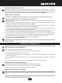
DETAILED SAFETY REGULATIONS
●Before connecting the sander to mains network ensure the supply voltage matches the voltage on the
rating plate of the tool.
●Connect the long reach sander only to electrical system equipped with residual current circuit breaker
that will cut the power o in less than 30 ms after earth leakage current exceeds 30 mA.
●Use dust extraction system with the sander.
●Before switching the sander on ensure the abrasive paper is well installed on the working pad and it does
not have contact with surface to be processed.
●Hold the sander rmly during operation.
●Do not touch moving parts of the sander.
●Wear anti-dust protective mask and protection glasses that adhere to face. Dust arising when sanding
plaster surfaces is harmful to health.
●Bystanders should not enter rooms where plaster is sanded. Do not eat or drink in the room.
●Do not operate the sander wet.
●Keep the power cord away from moving parts of the sander at all times.
●If the power cord is damaged during operation, disconnect the power supply immediately. DO NOT
TOUCH POWER CORD BEFORE DISCONNECTING THE POWER SUPPLY.
●WARNING. Working pad rotates for some time after the motor is switched o.
●Keep unwound power cord away from cutting parts.
●Do not allow children and persons not familiarized with instruction manual to operate the sander.
●REMEMBER. Operator or user is responsible for any accident or emerging hazards to other persons or
surrounding.
●Remove plug from mains socket:
- whenever you go away from the tool;
- before checking, cleaning or repairing the tool.
●Only authorised persons should repair the sander.
●Use only spare parts recommended by the manufacturer.
MAINTENANCE AND STORING
●Keep all components in good condition to ensure the sander works safely.
●To keep the operation safe, replace worn out and damaged parts.
●Protect the sander against moisture.
●Keep the tool beyond reach of children.
●Use appropriate type of sanding paper.
CAUTION! This device is designed to operate indoors.
The design is assumed to be safe, protection measures and additional safety systems are used,
nevertheless there is always a small risk of operational injuries.
Explanation of used symbols
1. Warning, use precaution measures
2. Read instruction manual, observe warnings and safety conditions therein!

14
3. Use individual protection measures (protective goggles, earmu protectors, anti-dust mask)
4. Disconnect the power cord before starting maintenance or operation.
5. Use protective clothes.
6. Use protective shoes.
7. Protect against humidity.
8. Protection class 2
CONSTRUCTION AND USE
Long reach sander is a hand power tool driven by a single-phase commutator motor. The sander is designed
for dry nishing sanding of walls, ceilings and other nishing coat surfaces. Two tilting axes of the sander
head allows to adhere to any surface of a ceiling or wall. Thanks to extension it is possible to operate without
a ladder. The sander is equipped with system that allows connecting external dust extraction system, which
must be operating when working with the sander. Range of use covers repair and building works, and any
work from the range of individual, amateur activities (tinkering).
Use the sander only with dust extraction system connected, e.g. industry or workshop vacuum
cleaner designed for sucking gypsum dust.
DESCRIPTION OF DRAWING PAGES
Below enumeration refers to the device elements depicted on the drawing pages of this manual.
1. Dust extraction hose
2. Arm
3. Wheel for rotational speed control
4. Switch
5. Clamp cap
6. Motor
7. Working pad cover
8. Working pad
9. Additional handle
10. Extension arm
11. Reducer sleeve
12. Suction hose
* Dierences may appear between the product and drawing.
MEANING OF SYMBOLS
CAUTION
WARNING
ASSEMBLY/SETTINGS
INFORMATION
EQUIPMENT AND ACCESSORIES
1. Extension arm - 1 pce
2. Reducer sleeves - 3 pcs
3. 1.2 m suction hose (4 m when stretched) - 1 pce
4. Shoulder strap - 1 pce
5. Sanding paper (various grades) - 14 pcs
6. Screwdriver - 1 pce
7. Hexagonal key - 1 pce
8. Transport bag - 1 pce

15
PREPARATION FOR OPERATION
INSTALLATION OF SANDING PAPER
The sander is equipped with working pad with hook-and-loop attachment, allowing quick and easy
replacement of sanding paper.
●Install sanding paper to working pad (8) so its holes match with holes in the working pad of the sander,
then press to ensure ecient dust extraction.
●To remove sanding paper, lift edge of it on one side and pull (g. A).
Use perforated sanding paper, so the dust can reach dust extraction system through holes in the
working pad. With each replacement of sanding paper clean the working pad, remove dust and all
dirt with e.g. brush.
EXTENDING THE ARM
Long reach sander can be used with short arm to sand walls and with arm extension, which improves range
for sanding e.g. ceilings.
●Loosen locking cap (5) of the extension (2).
●Place extension arm (10) in the arm pipe (2), slide the reducer sleeve (11) into xing of the clamp cap (5),
set desired length and tighten the clamp cap (5) (g. b).
DUST EXTRACTION
Install suction hose (12) to the arm tip (2) or extension arm (10).
●Loosen the clamp cap (5), slide suction hose end (12) into the hole and secure by tightening the clamp
cap (5) (g. C, D).
●Connect the other end of suction hose to a suction system, e.g. workshop vacuum cleaner (the cleaner
must be designed for gypsum dust extraction).
When starting the work, rst switch vacuum cleaner, next the sander. When the work is nished proceed
inversely – switch o the sander rst, then the vacuum cleaner. This procedure allows to avoid unnecessary
dustiness in the workplace. Some types of industrial or workshop vacuum cleaners are equipped with
power supply socket for power tools and switching the vacuum cleaner on and o is automated, controlled
with switching the power tool.
OPERATION / SETTINGS
SWITCHING ON / SWITCHING OFF
The mains voltage must match the voltage on the rating plate of the sander.
Switching on – change over the switch button (4) to position I (g. E).
Switching o – change over the switch button (4) to position O.
ROTATIONAL SPEED CONTROL
Wheel for speed control (3) is located on the sander body. Select the speed depending on your needs
(depending on the sanding paper used, hardness of processed material, type of work etc.). Rotating the
wheel for rotational speed control (3) increases or reduces speed of working pad (g. F).
SANDER OPERATION
Processed surfaces must be dry and must not contain foreign objects, e.g. screws, nails, bolts etc.
hold the sand rmly with both hands.
●Switch the sander on and wait until working pad reaches its full rotational speed.
●Put whole surface of the working pad to processed surface (articulated connection of working pad and
its cover will adjust to the surface automatically) (g. G).
●Apply moderate pressure and move the sander along processed surface with rotary movements, or
crosswise and lengthwise alternately.
●Overpressure will not increase sanding eciency, but may cause faster wear of sander parts and sanding
paper.

16
●Putting the working pad away from processed surface during operation will allow dust to get out of the
tool into the room where the work is carried out.
●Eciency and quality of processed surface depend heavily on type of sanding paper used and applied
pressure. It is best to match the type of sanding paper by trials and errors.
●When nishing sanding reduce pressure on the sander, switch o the motor and vacuum cleaner.
●Replace sanding paper when you observe signs of wear.
●Make periodic breaks in operation.
Do not switch the sander on while its working pad is pressed against processed surface.
OPERATION AND MAINTENANCE
Disconnect the tool from power supply network before starting any adjustment, maintenance or
repair.
●Always keep the sander clean.
●Do not use water or any other liquid for cleaning.
●Use brush to clean the sander.
●Clean ventilation holes of the sander regularly to prevent motor overheating.
●In case of excessive commutator sparking check technical condition of carbon brushes of the motor.
●Store the sander in a dry place, beyond reach of children.
WORKING PAD REPLACEMENT
Replace immediately worn out or damaged working pad.
●Loosen and unscrew the bolt that xes the working pad (8) (g. H).
●Replace the working pad with a new one, x with the bolt.
REPLACEMENT OF CARBON BRUSHES
Replace immediately worn out (shorter than 5 mm), burnt or cracked motor carbon brushes. Always
replace both carbon brushes at a time.
Entrust replacement of carbon brushes only to a qualied person. Only original parts should be
used.
All defects should be repaired by service workshop authorized by the manufacturer.
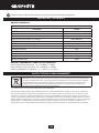
TECHNICAL PARAMETERS
RATED PARAMETERS
Long Reach Sander
Parameter Value
Supply voltage 230 V AC
Current frequency 50 Hz
Rated power 600 W
Range of spindle rotational speed without load 600-1500 min-1
Sander length 1100-2000 mm
Diameter of working pad 225 mm
Diameter of sanding paper 225 mm
Spindle thread M6
Protection class II
Protection level IP20
Weight 5,5 kg
Year of production 2022

17
NOISE LEVEL AND VIBRATION PARAMETERS
Sound pressure : LpA = 85 dB(A) K = 3 dB(A)
Sound power : LwA = 96 dB(A) K = 3 dB(A)
Weighted value of vibration acceleration : ah = 3,18 m/s2 K = 1,5 m/s2
ENVIRONMENT PROTECTION
Do not dispose of electrically powered products with household wastes, they should be utilized
in proper plants. Obtain information on wastes utilization from your seller or local authorities.
Used up electric and electronic equipment contains substances active in natural environment.
Unrecycledequipment constitutes a potential risk for environment and human health.
* Right to introduce changes is reserved.
“Grupa Topex Spółka z ograniczoną odpowiedzialnością” Spółka komandytowa with seat in Warsaw at ul. Pograniczna
2/4 (hereinafter Grupa Topex) informs, that all copyrights to this instruction (hereinafter Instruction), including, but not
limited to, text, photographies, schemes, drawings and layout of the instruction, belong to Grupa Topex exclusively and are
protected by laws accordingly to Copyright and Related Rights Act of 4 February 2004 (ustawa o prawie autorskim i prawach
pokrewnych, Dz. U. 2006 No 90 item 631 with later ammendments). Copying, processing, publishing, modications for
commercial purposes of the entire Instruction or its parts without written permission of Grupa Topex are strictly forbidden
and may cause civil and legal liability.

18
ÜBERSETZUNG DER ORIGINALBETRIEBSANLEITUNG
GIPSSCHLEIFER
59G261
ANMERKUNG: LESEN SIE VOR DER INBETRIEBNAHME DIESES ELEKTROWERKZEUGS GRÜNDLICH DIE
VORLIEGENDE BETRIEBSANLEITUNG DURCH UND BEWAHREN SIE SIE AUF.
DETAILLIERTE SICHERHEITSVORSCHRIFTEN
●Vor dem Anschließen des Schleifers ans Netz prüfen Sie stets, dass die Netzspannung der auf dem
Typenschild angegebenen Nennspannung des Gerätes entspricht.
●Den Gipsschleifer nur an die Elektroinstallation mit dem Dierenzstromschutz anzuschließen, die
Versorgung unterbrechen wird, falls der Leckstrom 30 mA innerhalb von 30 ms überschreiten wird.
●Die Staubabzugsanlage ist an den Schleifer anzuschließen.
●Prüfen Sie vor dem Einschalten des Schleifers, dass das Schleifpapier sicher an die Scheibe angebracht
ist und das Werkstück nicht berührt.
●Der Schleifer ist beim Betrieb fest zu halten.
●Berühren Sie keine beweglichen Teile des Schleifers.
●Die Staubschutzmaske und ans Gesicht anschmiegende Schutzbrille sind zu tragen. Der beim Schleifen
der Gipsoberächen entstehende Staub ist gesundheitsschädlich.
●Dritte dürfen den Raum, in dem Gips mit dem Gipsschleifer geschlien wird, nicht betreten. In einem
solchen Raum darf ebenfalls nicht gegessen oder getrunken werden.
●Der Schleifer darf nicht nass betrieben werden.
●Die Versorgungsleitung des Gerätes halten Sie stets fern von beweglichen Teilen des Schleifers.
●Falls das Netzkabel beim Betrieb beschädigt wird, schalten Sie unverzüglich die Netzversorgung aus.
●DIE LEITUNG VOR DEM AUSSCHALTEN DER NETZVERSORGUNG NICHT BERÜHREN.
●WARNUNG. Nach dem Ausschalten des Motors rotiert die Scheibe immer noch.
●Halten Sie das abgewickelte Netzkabel von der Scheibe fern.
●Lassen Sie keine Kinder und keine Personen, die mit der Betriebsanleitung nicht vertraut sind, mit dem
Gerät arbeiten.
●BEACHTEN Der Bediener oder Benutzer haftet für Unfälle oder vorhandene Gefahren gegenüber
anderen Personen oder der Umgebung.
●Trennen Sie den Stecker von der Steckdose:
- immer, wenn Sie vom Gerät weggehen;
- vor jeder Inspektion, Reinigung oder Reparatur des Gerätes;
●Mit der Reparatur des Schleifers nur qualizierte Fachkraft beauftragen.
●Nur die vom Hersteller empfohlenen Ersatzteile verwenden.
WARTUNG UND AUFBEWAHRUNG
●Alle Baugruppen im technisch einwandfreien Zustand halten, um den sicheren Betrieb des Schleifers zu
gewährleisten.
●Tauschen Sie gebrauchte oder beschädigte Teile aus, um den sicheren Betrieb zu gewährleisten.
●Vor Nässe schützen.
●Außerhalb der Reichweite von Kindern aufbewahren.
●Richtiges Schleifpapier verwenden.
ACHTUNG! Das Gerät ist für den betrieb in Innenräumen bestimmt.
Trotz dem Einsatz einer sicheren Konstruktion, von Sicherheitseinrichtungen und zusätzlichen
Schutzeinrichtungen besteht stets das Restrisiko einer Verletzung beim betrieb des Gerätes.

19
Erläuterung zu den eingesetzten piktogrammen
1. Achtung! Besondere Sicherheitsvorkehrungen beachten
2. Die Betriebsanleitung durchlesen und die darin enthaltenen Warnhinweise und Sicherheitshinweise
beachten!
3. Persönliche Schutzausrüstung (Schutzbrille, Gehörschutz, Staubschutzmaske) tragen.
4. Die Versorgungsleitung vor allen Wartungs- und Reparaturarbeiten abtrennen.
5. Schutzkleidung verwenden
6. Schutzschuhwerk verwenden
7. Vor Feuchte schützen
8. Zweite Schutzklasse
AUFBAU UND ANWENDUNG
Der Gipsschleifer mit Ausleger ist ein manuell bedienbares Elektrowerkzeug, das wird mit einem einphasigen
Kommutatormotor betrieben. Der Schleifer ist für das trockene Finish-Schleifen von Gipsoberächen wie
Wände, Decken und anderen Flächen, die mit dem Gipsfeinputz bearbeitet sind, bestimmt. Der in zwei
Ebenen schwenkbare Schleifkopf haftet wunderbar an die Decken-, bzw. Wandäche an. Mit dem Ausleger
lässt sich die Arbeit auch ohne Leiter ausführen. Der Schleifer ist mit einem System ausgestattet, das
den Anschluss an das externe Staubabsaugsystem (muss während des Betriebs eingeschaltet werden)
ermöglicht. Der Anwendungsbereich dieses Werkzeugs umfasst die Ausführung von Sanierungs- und
Bauarbeiten und aller Arbeiten, die Zuhause selbst durchgeführt werden (Heimwerker).
Der Schleifer ist ausschließlich mit dem angeschlossenen Staubabsaugsystem, z. b. Werkstatt-
Staubsauger, der für das Absaugen des Gipsstaubs ausgelegt ist, zu benutzen.
BESCHREIBUNG DER SEITEN MIT GRAPHIKEN
Die unten angeführte Nummerierung bezieht sich auf die Elemente des Gerätes, die auf den Seiten mit
Graphiken dargestellt werden.
1. Staubabsaugleitung
2. Ausleger
3. Drehzahleinstellring
4. Hauptschalter
5. Spannmutter
6. Motor
7. Scheibenabdeckung
8. Schleifscheibe
9. Zusatzgri
10. Verlängerungsstück für Ausleger
11. Reduktionshülse
12. Ansaugschlauch
* Es können Unterschiede zwischen der Abbildung und dem Produkt auftreten.
BESCHREIBUNG FÜR VERWENDETE GRAPHISCHE ZEICHEN
ACHTUNG
WARNUNG
MONTAGE/EINSTELLUNGEN
INFORMATION

20
AUSSTATTUNG UND ZUBEHÖR
1. Verlängerungsstück für Ausleger - 1 St.
2. Reduktionsbuchse - 3 St.
3. Ansaugschlauch 1,2 m, nach Ausrollen 4 m - 1 St.
4. Schultergürtel - 1 St.
5. Schleifpapier (unterschiedliche Körnung) - 14 St.
6. Schraubendreher - 1 St.
7. Sechskantschlüssel - 1 St.
8. Transporttasche - 1 St.
BETRIEBSVORBEREITUNG
BEFESTIGUNG DES SCHLEIFPAPIERS
Der Schleifer ist mit einer Scheibe mit dem Klettverschluss ausgestattet, der einen einfachen und schnellen
Austausch des Schleifpapiers ermöglicht.
●Das Schleifpapier an die Schleifscheibe (8) so ansetzen, dass seine Önungen mit den Önungen in
●der Schleifscheibe des Schleifers übereinstimmen und andrücken, um die Abführung des Staubes zu
gewährleisten.
●Um das Schleifpapier zu entfernen, soll man es an einer Seite zurückbiegen und anschließend ziehen
(Abb. A).
Setzen Siedasperforierte Schleifpapierein, damitder Staubdurchdie Önungeninder Schleifscheibe
in die Absaugung abgeführt werden kann. Vor jedem Austausch des Schleifpapiers ist die Scheibe
von Staub und allen Verunreinigungen mit einer bürste oder einem Pinsel zu reinigen.
AUSLEGER VERLÄNGERN
Der Gipsschleifer kann mit einem kurzen Ausleger zum Schleifen von Wänden oder mit einem
Verlängerungsstück, das die Reichweite des Werkzeugs vergrößert, zum Schleifen von Deckenächen
eingesetzt werden.
●Die Kontermutter (5) am Ausleger (2) lockern.
●Das Verlängerungsstück (10) in das Rohr des Auslegers (2) stecken, die Reduktionsbuchse (11) in die
Befestigung der Spannmutter (5) schieben, gewünschte Länge einstellen und die Spannmutter (5)
(Abb. b) festziehen.
STAUB ABFÜHREN
Den Ansaugschlauch (12) an das Endstück des Auslegers (2) oder das Verlängerungsstück (10) anbringen.
●Die Spannmutter (5) lockern, das Endstück des Ansaugschlauches (12) in die Önung einschieben und
mit der Spannmutter (5) (Abb. C, D) sichern.
●Das andere Endstück des Ansaugschlauches an das Staubabsaugsystem, z. B. einen Werkstatt-
Staubsauger anschließen (der Staubsauger muss für das Absaugen von Gipsstaub ausgelegt sein).
Beim Anfang der Arbeit zuerst den Staubsauger und dann den Schleifer einschalten. Nach dem Abschluss
der Arbeit umgekehrt vorgehen – zuerst den Schleifer und dann den Staubsauger ausschalten. Dadurch
wird der Arbeitsbereich nicht unnötig mit Staub erfüllt. In manchen Modellen der Werkstatt-Staubsauger,
die über eine Steckdose für Elektrowerkzeuge verfügen, erfolgt das Ein- und Ausschalten des Staubsaugers
automatisch und wird mit dem Hauptschalter des Elektrowerkzeugs gesteuert.
BETRIEB / EINSTELLUNGEN
EIN/AUSSCHALTEN
Die Netzspannung muss dem Spannungswert entsprechen, der im Typenschild des Schleifers
angegeben worden ist.
Einschalten – Die Taste des Hauptschalters (4) in die Pos. I (Abb. E) bringen.
Ausschalten – Die Taste des Hauptschalters (4) in die Pos. O bringen.
Pagina se încarcă...
Pagina se încarcă...
Pagina se încarcă...
Pagina se încarcă...
Pagina se încarcă...
Pagina se încarcă...
Pagina se încarcă...
Pagina se încarcă...
Pagina se încarcă...
Pagina se încarcă...
Pagina se încarcă...
Pagina se încarcă...
Pagina se încarcă...
Pagina se încarcă...
Pagina se încarcă...
Pagina se încarcă...
Pagina se încarcă...
Pagina se încarcă...
Pagina se încarcă...
Pagina se încarcă...
Pagina se încarcă...
Pagina se încarcă...
Pagina se încarcă...
Pagina se încarcă...
Pagina se încarcă...
Pagina se încarcă...
Pagina se încarcă...
Pagina se încarcă...
Pagina se încarcă...
Pagina se încarcă...
Pagina se încarcă...
Pagina se încarcă...
Pagina se încarcă...
Pagina se încarcă...
Pagina se încarcă...
Pagina se încarcă...
Pagina se încarcă...
Pagina se încarcă...
Pagina se încarcă...
Pagina se încarcă...
Pagina se încarcă...
Pagina se încarcă...
Pagina se încarcă...
Pagina se încarcă...
Pagina se încarcă...
Pagina se încarcă...
Pagina se încarcă...
Pagina se încarcă...
Pagina se încarcă...
Pagina se încarcă...
Pagina se încarcă...
Pagina se încarcă...
Pagina se încarcă...
Pagina se încarcă...
Pagina se încarcă...
Pagina se încarcă...
Pagina se încarcă...
Pagina se încarcă...
Pagina se încarcă...
Pagina se încarcă...
Pagina se încarcă...
Pagina se încarcă...
Pagina se încarcă...
Pagina se încarcă...
Pagina se încarcă...
Pagina se încarcă...
Pagina se încarcă...
Pagina se încarcă...
Pagina se încarcă...
Pagina se încarcă...
Pagina se încarcă...
Pagina se încarcă...
Pagina se încarcă...
Pagina se încarcă...
Pagina se încarcă...
Pagina se încarcă...
Pagina se încarcă...
Pagina se încarcă...
Pagina se încarcă...
Pagina se încarcă...
Pagina se încarcă...
Pagina se încarcă...
Pagina se încarcă...
Pagina se încarcă...
Pagina se încarcă...
Pagina se încarcă...
Pagina se încarcă...
Pagina se încarcă...
Pagina se încarcă...
Pagina se încarcă...
Pagina se încarcă...
Pagina se încarcă...
-
 1
1
-
 2
2
-
 3
3
-
 4
4
-
 5
5
-
 6
6
-
 7
7
-
 8
8
-
 9
9
-
 10
10
-
 11
11
-
 12
12
-
 13
13
-
 14
14
-
 15
15
-
 16
16
-
 17
17
-
 18
18
-
 19
19
-
 20
20
-
 21
21
-
 22
22
-
 23
23
-
 24
24
-
 25
25
-
 26
26
-
 27
27
-
 28
28
-
 29
29
-
 30
30
-
 31
31
-
 32
32
-
 33
33
-
 34
34
-
 35
35
-
 36
36
-
 37
37
-
 38
38
-
 39
39
-
 40
40
-
 41
41
-
 42
42
-
 43
43
-
 44
44
-
 45
45
-
 46
46
-
 47
47
-
 48
48
-
 49
49
-
 50
50
-
 51
51
-
 52
52
-
 53
53
-
 54
54
-
 55
55
-
 56
56
-
 57
57
-
 58
58
-
 59
59
-
 60
60
-
 61
61
-
 62
62
-
 63
63
-
 64
64
-
 65
65
-
 66
66
-
 67
67
-
 68
68
-
 69
69
-
 70
70
-
 71
71
-
 72
72
-
 73
73
-
 74
74
-
 75
75
-
 76
76
-
 77
77
-
 78
78
-
 79
79
-
 80
80
-
 81
81
-
 82
82
-
 83
83
-
 84
84
-
 85
85
-
 86
86
-
 87
87
-
 88
88
-
 89
89
-
 90
90
-
 91
91
-
 92
92
-
 93
93
-
 94
94
-
 95
95
-
 96
96
-
 97
97
-
 98
98
-
 99
99
-
 100
100
-
 101
101
-
 102
102
-
 103
103
-
 104
104
-
 105
105
-
 106
106
-
 107
107
-
 108
108
-
 109
109
-
 110
110
-
 111
111
-
 112
112


Graphite 59G261 Manualul proprietarului
- Categorie
- Accesorii mixer / robot de bucătărie
- Tip
- Manualul proprietarului
în alte limbi
- slovenčina: Graphite 59G261 Návod na obsluhu
Lucrări înrudite
-
Graphite 59G264 Manualul proprietarului
-
-
-
-
-
-
-
-
-


