Pagina se încarcă...

Operating Instructions
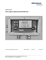
Minebea Intec EC1XS.-......-L Series
Electronic Stainless Steel Scales for
Use in Hazardous Areas
98648-013-47
98648-013-47

2 EC1XS... EC1XS... 3
Contents
2 Keypad
3 Operating Design
4 Operation
4 Weighing
5 Calibration/Adjustment
6 Application Programs
6 Toggling between Weight Units
7 Gross/Net Toggling
8 Data Output Functions
9 Interface Port
11 Synchronization
12 Configuration
14 Operating Menu Overview
16 Troubleshooting Guide
17 Specifications
17 Dimensions
19 Accessories (Options)
20 Installing a Column
21 Certificates
The following symbols are used in
these instructions:
§ indicates required steps
$ indicates steps required only under
certain conditions
> describes what happens after you have
performed a particular step
– indicates an item in a list
! indicates a hazard
Make sure you observe the warning
and safety information (see enclosed
separate manual) in its entirety dur-
ing installation and operation, as well
as while performing maintenance and
repair work on the equipment. It is
important that all personnel using the
equipment understand this information,
and have access to it at all times.
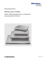
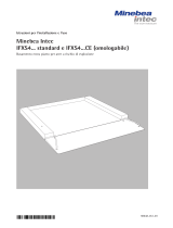
Keypad
1 p [Print] key: data output
2 k [Function] key: toggle weight unit
3 ) [Tare] key: tare the scale
4 ( [Zero] key: zero the scale
5 e [On/Off/Standby] key: switch the scale on or off, or put it in standby mode
1
2
3
4
5

2 EC1XS... EC1XS... 3
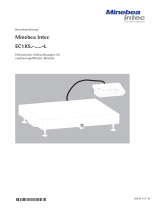
Display
1) Busy symbol, plus/minus sign, stability
symbol
Indicates a routine in progress (internal
processing).
2) Plus or minus sign (+ or -)
Applies to the displayed weight value.
3) Measured value
Weight readout; when the operating
menu is active, menu codes are shown
here. Application parameters are also
displayed here.
4) Unit
Weight units
5) Print symbol
Indicates printing in progress.
6) Net value
Indicates a net value on the readout.
– When gross/net toggling is active “NET”
Input
In Setup mode (operating menu active),
input consists in selecting parameters
from a list, accessible in the form of
a 3-level menu.
To activate the Setup mode, switch
on the scale and, while all segments are
displayed during power-up, press the
) [Tare] key briefly. To scroll through
the items on one menu level, press )
[Tare] briefly (repeatedly as needed);
if you press [Tare] again after the last
item is reached, the first item is dis-
played again.
To change menu levels, press the p
[Print] key briefly.
To select a parameter on the 3rd menu
level, press and hold the p [Print] key
(2 sec).
“*” indicates the active setting.
See “Configuration” for the entire list
of parameter options.
To save changes and exit the menu,
press and hold the ) [Tare] key
(2 sec).
12
5
34
6
4
4
Operating Design
The EC1XS-......-L series complete scale
is designed for mass determination in
zone 1, 2, 21 and 22 hazardous areas.
The scale consists of a weighing plat-
form and a display and control unit
(evaluation unit). In addition to the
basic weighing function, the complete
scale is equipped with programs for
toggling weight units and gross/net
weighing. Weight values can be trans-
ferred through a Zener barrier (e.g.,
option YDI05-Z) over an RS-232 port
(built-in) or an RS-422 port (optional)
to a printer or computer outside the
hazardous area. A foot switch can also
be connected to the scale.
An external power supply is required for
operation of the scale (option YPS05-X..
for installation in the hazardous area, or
YPS05-Z.. for the non-hazardous area).
Operation of the complete scale
follows a uniform philosophy, which is
described below.
Keys
You can operate the scale either using
the keys on the display and control
unit or from a connected computer.
Some keys have a second function,
activated by holding the key for
2 seconds rather than pressing briefly
(less than 2 seconds).
Operating menu settings are stored in
battery-backed memory. When you turn
on the scale, the most recent configura-
tion settings are active.
To exit the menu without saving
changes, press the e [On/Off/Stand-
by] key.
Data Output
The following interfaces are available
for data transfer:
- RS-232 (standard feature)
- RS-422 (optional accessory)
You can also connect a universal remote
control switch (foot switch) to the scale.
Please refer to “Documents for
Hazardous Areas” in the enclosed
“Installation Instructions and Safety
Information” manual.
Printer
Data output to the printer can be
adapted to certain requirements by
selected the corresponding settings in
the operating menu.
Printouts can be generated at the press
of a key (p [Print]) or automatically,
either dependent on or independent
of stability. You can also define whether
ID codes are included on the printout.
For details, see “Data Output Functions”
in the chapter entitled “Operation.”
Interface Port
You can connect a printer or other
peripheral device (such as a computer)
to the interface port. With a computer,
you can transmit commands over scale
interface to trigger and control certain
functions in the compact scale.
See “Data Output Functions” in the
chapter entitled “Operation” for a
detailed description of data output
options.
Error Messages
Error messages are displayed as follows
for 2 seconds:
- Operational error: “E” + 2 digits
- Hardware error: “E” + 3 digits
3- digit error messages are not cleared
after 2 seconds. If a 3-digit error
message appears, notify your nearest
Minebea Intec Service Center.
See the chapter entitled “Troubleshoot-
ing Guide” for detailed explanations
of error codes and messages.

4 EC1XS... EC1XS... 5
Operation
Weighing
Purpose
The basic weighing function is available
in the compact scale at all times.
You can use this function alone, or in
combination with the application
programs (Toggling between weight
units, Gross/net toggling).
Features
– Zero the scale
Sometimes the scale does not show
a zero readout even though there is no
load on the weighing pan. This is gen-
erally due to unfavorable ambient con-
ditions. If the difference to zero does
not exceed 2% of the scale’s maximum
capacity, it can be corrected by zeroing
the scale.
– Tare the scale
To obtain a readout of the net weight
of a sample in a container, place the
empty container on the scale and press
the ) [Tare] key before adding the
sample.
– Print the results (optional connec-
tion) or transfer data over the interface
(optional connection) to a computer.
Example
Simple weighing
Settings: factory settings
Step Key (or instruction) Display/Data output
1. Switch on the scale e [On/Off/Standby] key 0.0 kg
2. If necessary, zero the scale ( [Zero] key 0.0 kg
(S symbol: scale zeroed)
3. Place container on the scale +15.0 kg
(in this example: 15.0 kg)
4. Tare the scale ) [Tare] key 0.0 kg
5. Place sample in container +125. 0 kg
(in this example: 125.0 kg)
6. Print result* p [Print] key ACE HARDWARE
GOETTINGEN
N + 125.0 kg
T + 15.0 kg
G# + 140.0 kg
* Two customer-specific lines can be
configured by the Minebea Intec customer
service center or your supplier.
A software program is available
for this purpose.
Factory Settings
Weight unit 1: kilograms (1 7 3)
Manual/auto print mode: manual after
stability (6 1 2)
Printout format: gross, tare and net
value with ID codes (7 1 3)
Preparation
§ Press e to switch on the scale
> Self-test runs
§ Set parameters as needed: see the chap-
ter entitled “Configuration” for details
§ Load factory settings if desired: see
parameter 9 – 1 in the chapter entitled
“Configuration”
Additional functions of the compact
scale:
– Activate an application
– Toggle the display between the weight
value and the value calculated in the
selected application

4 EC1XS... EC1XS... 5
Calibration/Adjustment
Purpose
Calibration means to determine the
difference between the scale readout
and the actual weight on the scale,
to determine the scale’s accuracy.
Adjustment means to bring the scale
to the level of accuracy required for
its use.
Features
Calibration/adjustment can be
performed only when
– there is no load on the scale,
– the scale has been zeroed, and
– the internal signal is stable.
If these conditions are not met, an error
message is displayed (E 02).
The weight displayed for the sample
on the scale must not differ from the
nominal weight by more than 2%.
External adjustment can be performed
using any of the following weight units:
g, kg, lb (1 4 1 )
External calibration/adjustment can be
blocked (1 5 2 )
Factory Settings
Weight unit for external calibration/
adjustment: kg (1 4 2)
External adjustment function:
accessible (1 5 1)
Example
Calibration and adjustment
Settings: factory settings
Step Key (or instruction) Display/Data output
1. Switch on the scale e [On/Off/Standby] key 0.0 kg
2. If necessary, zero the scale ( [Zero] key 0.0 kg
3. Start calibration ) [Tare] key + 50.0
Calibration weight is displayed (press and hold >2 sec)
without weight unit
4. Apply the prompted calibration 50.0
weight (in this example: 50.00 kg)
After adjustment, the calibration + 50.0 kg
weight is displayed with weight unit
5. Remove the calibration weight 0.0 kg
1. Switch on the scale e [On/Off/Standby] key 0.0 kg
2. If necessary, zero the scale ([Zero] key 0.0 kg
3. Start calibration )[Tare] key + 50.0
Calibration weight is displayed (press and hold >2 sec)
without weight unit
4. Apply the prompted calibration 50.0
weight (in this example: 50.00 kg)
After adjustment, the calibration + 50.0 kg
weight is displayed with weight unit
5. Calibration weight /CAL
is displayed
50.0 / CAL
) [Tara]-key +50.0 kg
(press and Hold >2sek
After adjustment, the calibration
weight is displayed with weight unit
6.
5. Remove the calibration weight 0.0 kg
7.

6 EC1XS... EC1XS... 7
Application Programs
Toggling between Weight Units
Purpose
With this application program you can
switch the display of a weight value
back and forth between two weight
units.
Features
– Toggle the weight unit
– Other features as with basic weighing
function
Factory Settings
Weight unit 1: kg (1 7 3)
Weight unit 2: kg (3 1 3)
Toggling between Weight Units
Select “Toggle weight units” in the
operating menu as follows:
$ To activate the operating menu, switch
off the scale by pressing e [On/Off/
Standby]; switch the scale back on (e
[On/Off/Standby]) and while all seg-
ments are lit, press the ) [Tare] key
briefly.
§ Select the “Toggling between weight
units” menu item:
Press ) [Tare], p [Print], p
[Print], ) [Tare], repeatedly as needed
> Toggling between weight units menu
code: 2 1 2
§ Confirm selection: press and hold p
[Print] key (2 sec)
> “o” indicates the active setting
§ Set other parameters: press the p
[Print] key
§ Select and confirm the following:
– Weight unit 1: see next page for details
(1 7 x)
– Display accuracy 1:
1 8 1 Standard
1 8 3 Increased resolution
– Weight unit 2: see next page for details
(3 1 x)
– Display accuracy 2:
3 2 1 Standard
3 2 3 Increased resolution
For details, see “Operating Menu
Navigation” in the chapter entitled
“Configuration.”
§ Save settings and close the menu: press
and hold the ) [Tare] key (2 sec)
Additional Functions
In addition to:
– switching off the scale (e [On/Off/Standby] key),
– zeroing the scale(( [Zero] key),
– taring the scale () [Tare] key) and
– printing (p [Print] key), the following functions can also be used with this
application program:
– Switch from weight unit 1 to weight unit 2 (k [Function] key)
– Calibrate/adjust the scale () [Tare] key 2 sec)
Menu code Unit Conversion Printout
(1 7 2) (3 1 2) Grams 1.00000000000 g
(1 7 3) (3 1 3) Kilograms 0.00100000000 kg
(1 7 4) (3 1 4) Carats 5.00000000000 ct
(1 7 5) (3 1 5) Pounds 0.00220462260 lb
(1 7 6) (3 1 6) Ounces 0.03527396200 oz
(1 7 7) (3 1 7) Troy ounces 0.03215074700 ozt
(1 7 8) (3 1 8) Hong Kong taels 0.02671725000 tlh
(1 7 9) (3 1 9) Singapore taels 0.02645544638 tls
(1 7 10) (3 1 10) Taiwanese taels 0.02666666000 tlt
(1 7 11) (3 1 11) Grains 15.43235835000 GN
(1 7 12) (3 1 12) Pennyweights 0.64301493100 dwt
(1 7 13) (3 1 13) Milligrams 1000.00000000000 mg
(1 7 14) (3 1 14) Parts per pound 1.12876677120 /lb
(1 7 15) (3 1 15) Chinese taels 0.02645547175 tlc
(1 7 16) (3 1 16) Mommes 0.26670000000 mom
(1 7 17) (3 1 17) Austrian carats 5.00000000000 K
(1 7 18) (3 1 18) Tola 0.08573333810 tol
(1 7 19) (3 1 19) Baht 0.06578947437 bat
(1 7 20) (3 1 20) Mesghal 0.21700000000 MS
(1 7 21) (3 1 21) Tons 0.00000100000 T
(1 7 22) (3 1 22) lb/oz 0.03527396200 o

6 EC1XS... EC1XS... 7
Example
Toggle weight units from kilograms [kg] (1st weight unit) to Troy ounces [ozt] (2nd weight unit)
Settings (changes in the factory settings required for this example):
Application program: Toggling between weight units (2 1 2)
Weight unit 2: pounds (3 1 7)
Step Key (or instruction) Display/Data output
1. Switch on scale e [On/Off/Standby] key
2. Place load on scale
(in this example: 22.95 kg) + 229.5 kg
3. View weight in pounds [lb] k [Function] key + 506.0 lb
4. Print result p [Print] key ACE HARDWARE
GOETTINGEN
G + 506.0 lb
5. View weight in kilograms [kg] k [Function] key + 229.5 kg
Purpose
Use this program to toggle the scale
between net and gross values.
Features
- Toggle between display of net value
and of gross value (when tare value is
in memory)
- Menu code 2 1 9
Preparation
Select “Gross/net toggling” in the oper-
ating menu as follows:
$ To activate the operating menu, switch
off the scale by pressing e [On/Off/
Standby]; switch the scale back on (e
[On/Off/Standby]) and while all seg-
ments are lit, press the ) [Tare] key
briefly.
§ Select the “Gross/net toggling” menu
item:
Press ) [Tare], p [Print], p
[Print], ) [Tare], repeatedly as needed
> Gross/net toggling menu code: 2 1 9
§ Confirm selection: press and hold p
[Print] key (2 sec)
> “o” indicates the active setting
§ Set other parameters: Press the p
[Print] key
§ Save settings and close the menu: press
and hold the ) [Tare] key (2 sec)
Example of a printout
Net value (p [Print] key):
N + 1250.0 kg
T + 150.0 kg
G# + 1400.0 kg
Gross value (p [Print] key):
G + 1400.0 kg
Gross/Net Toggling

8 EC1XS... EC1XS... 9
Data Output Functions
There are three options for data output:
- Output to the scale display
- Printout
- Output over the interface port to a
peripheral device (e.g., a computer)
Generating a Printout
Purpose
You can generate printouts that include
weights, other measured values and
identification codes for documentation
purposes. You can format the printout
to meet individual requirements.
Features
You can include two customer-specific
header lines of up to 14 characters
each on the printout (configured by
Minebea Intec at the factory or using a
special software program available from
Minebea Intec).
You can print individual values, or net,
tare and gross values.
Line format: you can have the values
printed with up to 6 preceding charac-
ters for identification.
Generating the printout: have printouts
generated automatically or by pressing
p; dependent on or independent of
stability
Factory Settings
Headers:
When default settings are active, there
are no header lines.
Manual/auto print mode:
individual printouts, or automatic and
dependent on scale stability:
Manual after stability (7 1 2)
Line Format:
Up to 6 characters at the beginning
of each line to identify the weight or
calculated value:
Print net, tare and gross values with ID
codes (7 1 3)
§ Setting the parameters:
see “Configuration”
Example of Headers:
Each printout can be have up to 2 header lines at the top.
Software for configuring headers is available from Minebea Intec.
ACE HARDWARE Customer-specific
GOETTINGEN The value currently
The value currently + 1530.0 g Weight in grams
displayed is printed + 58.562 ozt Weight in Troy ounces
(weight value or weight unit) + 105.8 Calculated value
Printout with Data ID Codes:
The current value on the N + 1530.0 kg Current net value
display is printed with an ID T + 234.0 kg Value in tare memory
code. The code is printed at G + 1553.0 kg Current gross value
the beginning of the line
(far left) and includes up
to 6 characters.
Automatic Printing:
You can have the result N +1530.0 kg Net weight
printed automatically. Stat Display blank
The interval is depend- Stat L Display underload
ent on the scale oper- Stat H Display overload
ating status and model.

8 EC1XS... EC1XS... 9
Interface Port
Purpose
An optional RS-422 interface can be
installed in the compact scale for con-
necting a computer or other peripheral
device (over an interface converter) in
the non-hazardous area.
You can use a connected computer to
change, start and/or monitor the func-
tions of the scale and the application
programs.
Features
Type of interface: serial interface
Operating mode: full duplex
Standard: RS-232
Transmission rate: 150, 300, 600, 1200,
2400, 4800 or 9600 baud
Parity: mark, space, odd, even
Character format: 1 start bit, 7-bit
ASCII, parity, 1 or 2 stop bits
Handshake:
For 2-wire interface: software (XON/
XOFF)
For 4-wire interface: hardware (CTS/
DTR)
Operating mode: SBI
Scale data output format:
16 or 22 characters
Factory Settings
Transmission rate: 1200 baud (5 1 4)
Parity: odd (5 2 3)
Stop bits: 1 stop bit (5 3 1)
Handshake: hardware handshake,
1 character after CTS (5 4 3)
Operating mode: standard SBI (5 5 1)
Manual/automatic printing: manual
after stability (6 1 2)
Preparation
§ For pin assignments and charts, please
refer to “Documents for Hazardous
Areas” in the “Installation Instructions
and Safety Information” manual
supplied with the scale.
Data Output Format
Whether or not the data ID code is included in the output depends on your settings in the
operating menu (Printing: Format: 7 1 1, 7 1 2 or 7 1 3).
When data ID codes are included, each line has 22 characters. Otherwise, the lines have
16 characters.
Data Output Format with 16 Characters
Display segments that are not activated are output as spaces. Values with no decimal point
are output without a decimal point. The type of character that can be output depends on
the character’s position:
Normal Operation
Position 1 2 3 4 5 6 7 8 9 10 11 12 13 14 15 16
+ * D D D D D D D D * U U U CR LF
or - . . . . . . . . * * *
or * * * * * * * * *
or 0 0 0 0 0 0
*: Space CR: Carriage return
D: Digit or letter LF: Line feed
U: Unit symbol
Special Codes
Position 1 2 3 4 5 6 7 8 9 10 11 12 13 14 15 16
* * * * * * - - * * * * * * CR LF
or H *
or L *
or C *
*: Space H: Overload
- -: Final readout mode L: Underload
C: Calibration/adjustment
Error Codes
Position 1 2 3 4 5 6 7 8 9 10 11 12 13 14 15 16
* * * E r r * # # # ** * * CR LF
*: Space
# # #: Error code number
Example: output of the weight value +1255.7 g
Position 1 2 3 4 5 6 7 8 9 10 11 12 13 14 15 16
+ * * * 1 2 5 5 . 7 * g * * CR LF
Position 1: Plus or minus sign or space
Position 2: Space
Positions 3 – 10: Weight with a decimal point; leading zeros = space
Position 11: Space
Positions 12 – 14: Unit symbol or space
Position 15: Carriage return
Position 16: Line feed

10 EC1XS... EC1XS... 11
Data Output Format with 22 Characters
When data is output with an ID code, the 6-character code precedes the 16-character string
described above. The code identifies the subsequent value.
1 2 3 4 5 6 7 8 9 10 11 12 13 14 15 16 17 18 19 20 21 22
I I I I I I + * D D D D D D D D * U U U CR LF
* * * * * - . . . . . . . . * * *
* * * * * * * * * 0 0 0 0 0 0
I: ID code character1) U: Unit symbol
*: Space
CR: Carriage return
D: Digit or letter LF: Line feed
Special Codes
1 2 3 4 5 6 7 8 9 10 11 12 13 14 15 16 17 18 19 20 21 22
S t a t * * * * * * * * - - * * * * * * CR LF
H *
L *
*: Space H: Overload
- -: Final readout mode L: Underload
Error Codes
1 2 3 4 5 6 7 8 9 10 11 12 13 14 15 16 17 18 19 20 21 22
S t a t * * * * * E R R * # # # * * * * CR LF
*: Space # # #: Error code number
Characters for ID
code I Meaning
Stat Status
G Gross
G# Gross G calculated
T Tare T
T1 Tare T1
N Net N
N1 Net N1
Data Input Format
The computer connected to the inter-
face can be used to send commands to
control scale functions and application
programs. These are control commands
and may have different formats. Control
commands consist of up to 4 characters.
Each character must be transmitted
according to the settings configured in
the operating menu for data transmis-
sion.
Format for Control Commands
Format 1: Esc ! CR LF
Esc: Escape
CR: Carriage return (optional)
!: Command character
LF: Line feed (optional)
Command
character ! Meaning
K Weighing mode 1
L Weighing mode 2
M Weighing mode 3
N Weighing mode 4
O Block keys
P Print
R Unblock keys
S Restart
U Tare the scale (tare only)
V Zero the scale
W External calibration

10 EC1XS... EC1XS... 11
Synchronization
During data communication between
the scale and a connected device (com-
puter), messages consisting of ASCII
characters are transmitted via the inter-
face. For error-free data communica-
tion, the parameters for baud rate,
parity, handshake mode and character
format must be the same for both units.
You can set these parameters in the
Setup menu so that they match those
of the connected device. If you do not
connect a peripheral device to the
interface port, this will not generate
an error message.
Female Interface Connector:
For pin assignments, see the “Installa-
tion Instructions and Safety Informa-
tion” manual supplied with the scale.
Handshake
The scale interface (Minebea Intec
Balance Interface = SBI) has transmit
and receive buffers. You can define
the handshake parameter in the Setup
menu:
– Hardware handshake (CTS/DTR)
– Software handshake (XON, XOFF)
Hardware Handshake
With a 4-wire interface, 1 more
character can be transmitted after CTS
(Clear to Send).
Software Handshake
The software handshake is controlled
via XON and XOFF. When a device is
switched on, XON must be transmitted
to enable any connected device to com-
municate.
Data Output by Print Command
The print command can be transmitted
by pressing the p [Print] key or via
software command (Esc P).
Automatic Data Output
Activate the “auto print” operating
mode to have data output to the inter-
face port without a print command.
You can have data output automatically
at defined display update intervals,
with or without the stability parameter.
The length of a print interval depends
on the operating menu settings for
Ambient conditions (menu code 1 1 x).
If you activate the auto print setting,
data will be transmitted immediately
the moment you turn on the scale.

12 EC1XS... EC1XS... 13
Operating Menu Navigation
Purpose
You can configure the scale by choos-
ing from parameters options in the
Setup menu to adapt the scale to indi-
vidual requirements.
Features
The parameters are combined in the
following groups (highest menu level):
1 Scale functions
2 Application programs
3 Application parameters
5 Interface
6 Printout in weighing mode
7 Printouts from application programs
8 Extra functions
9 Reset (restore factory settings)
Factory Settings
Factory-set parameters are identified by
an “o” in the list on the following pages
(“Operating Menu Overview”).
Preparation
§ Switch off the scale: press the e [On/
Off/Standby] key
§ Switch the scale back on: press e
[On/Off/Standby]; while all segments
are lit: press the ) [Tare] key briefly
> Measured value/result line: 1 (1st menu
level)
$ To scroll through the items on one
menu level, press: ) [Tare]; after
the last item is reached, the first is dis-
played again
$ To confirm the highlighted item and
open the submenu (2nd menu level),
press p [Print]
$ To return to the next higher menu level,
press p [Print]
§ To confirm a new setting, press and
hold p [Print] (2 sec)
> “o” indicates the active setting
§ To save changes and exit the menu,
press and hold the ) [Tare] key (2
sec)
§ To exit without saving changes, press
e [On/Off/Standby]
> Restart the application
Configuration

12 EC1XS... EC1XS... 13
Example
Adapting the scale to “very unstable” ambient conditions (menu code 1 1 4)
Step Key (or instruction) Display/Data output
1. Switch off the scale e [On/Off/Standby]
2. Switch the scale back on; e [On/Off/Standby]
while all segments are lit Press briefly:
) [Tare] ) [Tare]
3. Confirm the “Bal./scale functions”
menu item (1st level) p [Print]
4. Confirm the “Adapt filter”
menu item (2nd level) p [Print]
5. 3rd menu level:
Select a setting Repeatedly:
) [Tare]
6. Confirm setting Press and hold 2 sec:
p [Print]
7. Set other parameters as
desired p [Print]
) [Tare]
8. Store settings and Press and hold 2 sec:
exit menu ) [Tare]

14 EC1XS... EC1XS... 15
o Factory setting
√ User-defined setting
Menu 1 Weighing 1.1 Adapt filter 1.1.1 Very stable conditions
(ambient conditions) 1.1.2 o Stable conditions
1.1.3 Unstable conditions
1.1.4 Very unstable conditions
1.2 Application filter 1.2.1 o Weighing
1.2.2 Filling mode
1.3 Stability range 1.3.1 1/4 digit
1.3.2 1/2 digit
1.3.3 1 digit
1.3.4 o 2 digits
1.3.5 4 digits
1.4 Weight unit 1.4.1 Grams
for calibration weight 1.4.2 o Kilograms
1.4.3 Pounds
1.5. Adjustment 1.5.1 o Accessible
1.5.2 Blocked
1.6 Auto zero 1 6 1 o On
1.6.2 Off
1.7 Weight unit 1 1.7.2 Grams
1.7.3 o Kilograms
1.7.4 Carats
1.7.5 Pounds
1.7.6 Ounces
1.7.7 Troy ounces
1.7.8 Hong Kong taels
1.7.9 Singapore taels
1.7.10 Taiwanese taels
1.7.11 Grains
1.7.12 Pennyweights
1.7.13 Milligrams
1.7.14 Parts per pound
1.7.15 Chinese taels
1.7.16 Mommes
1.7.17 Austrian carats
1.7.18 Tola
1.7.19 Baht
1.7.20 Mesghal
1.7.21 Tons
1.7.22 Pounds/ounces (no decimal places)
1.8 Display accuracy 1.8.1 o Standard
1.8.3 Higher resolution
Menu 2 Application 2.1 Program selection 2.1.1 o Basic weighing function
programs 2.1.2 Toggle weight units
2.1.9 Gross/net toggling
Menu 3 Application 3.1 Weight unit 2 3.1.2 Grams
parameters 3.1.3 o Kilograms
3.1.4 Carats
3.1.5 Pounds
3.1.6 Ounces
3.1.7 Troy ounces
3.1.8 Hong Kong taels
3.1.9 Singapore taels
3.1.10 Taiwanese taels
Operating Menu Overview
Menu level 1
Menu level 2
Menu level 3
Factory setting
Menu item

14 EC1XS... EC1XS... 15
3.1.11 Grains
3.1.12 Pennyweights
3.1.13 Milligrams
3.1.14 Parts per pound
3.1.15 Chinese taels
3.1.16 Mommes
3.1.17 Austrian carats
3.1.18 Tola
3.1.19 Baht
3.1.20 Mesghal
3.1.21 Tons
3.1.22 Pounds/ounces (no decimal places)
3.2. Display 3.2.1 o Standard
accuracy 2 3.2.3 Higher resolution
Menu 5 Interface 5.1 Baud rate 5.1.1 150 baud
5.1.2 300 baud
5.1.3 600 baud
5.1.4 o 1200 baud
5.1.5 2400 baud
5.1.6 4800 baud
5.1.7 9600 baud
5.2 Parity 5.2.1 Mark
5.2.2 Space
5.2.3 o Odd
5.2.4 Even
5.3 Number of stop bits 5 3 1 o 1 stop bit
5.3.2 2 stop bits
5.4. Handshake 5 4 1 Software
mode 5.4.2 Hardware, 1 character after CTS
5.4.3 o Hardware, 2 character after CTS
5.5 Communication 5.5.1 o Computer or YDP03 printer (SBI)
mode 5.5.2 YDP04IS printer*
Menu 6 Printout in 6.1 Manual/automatic 6.1.1 Manual without stability
weighing mode printing 6.1.2 o Manual after stability
6.1.3 Autom. w/o stability
6.1.4 Automatic at stability
Menu 7 Printouts from 7.1 Line format of 7.1.1 W/o data ID codes
application printout programs 7.1.2 With data ID (22 characters)
7.1.3 o with data ID., N/T/G values
and 2 header lines
Menu 8 Additional 8.1. Menu 8.1.1 o Settings can be changed
functions
8.1.2 Read only
8.2 Universal switch 8.2.3 ) [Tare] key
8.3 Switching on 8.3.1 Off/on
the scale 8.3.2 o Standby/on
Menu 9 Reset 9.– Factory settings 9.– 1 Restore factory settings
9.– 2 o Do not restore factory settings
* = When using the YDP04IS printer, select menu codes 5.1.7, “9600 baud,” and 5.3.2, “2 stop bits”
Menu level 1
Menu level 2
Menu level 3
Factory setting
Menu item

16 EC1XS... EC1XS... 17
Troubleshooting Guide
Error codes are shown on the main display for approx. 2 seconds. The program then returns automatically to the previous mode.
Display Cause Solution
No segments appear on the display No AC power is available Check the AC power supply
Power supply not plugged in Connect power supply to the
wall outlet (mains)
Automatic shutoff Switch on the scale
h The load exceeds the scale capacity Unload the scale
l No load plate on the scale Place the load plate on the scale
Something is touching the load plate Move the object that is touching the load plate
e 01 Data output not compatible with output Change the configuration in the operating menu
format
e 02 Calibration parameters not met; Calibrate only when zero is displayed
for example:
– Scale not zeroed Press ( [Zero] key
– Load on load plate Unload the scale
e 08 Readout not in range for zero-setting Zeroing only possible when
value is ±2% of max capacity
e 09 No tare possible when gross ≤ 0 Press ( [Zero] to zero
e 10 ) [Tare] key blocked when there Press the k [Function]
is data in 2nd tare memory key to clear the tare memory
(net-total app.); only one tare
function can be used at a time
e 11 Tare memory not allowed Press the ( [Zero] key
e 22 Load is too light or no Increase weight on load plate
sample on the load plate
e 30 Interface port for printer Restore factory menu settings
output is blocked or
Contact your local Minebea Intec Service Center
Max. weighing capacity less than Scale was switched on without Switch the scale off and then
listed in “Specifications” load plate in place on again: press e [On/Off/Standby] key
The weight readoutchanges constantly Unstable ambient conditions excessive Set up the scale in another area or
(vibration or draft) adjust menu settings
A foreign object is caught between Remove the foreign object
the load plate and scale housing
The weight readout is obviously wrong The scale was not calibrated/adjusted Calibrate/adjust the scale
Scale not zeroed before weighing Zero the scale
If any other errors occur, contact your local Minebea Intec Service Center.

16 EC1XS... EC1XS... 17
Specifications
Model EC1XS.-......-L
Weighing capacity 3 kg to 3 t
Sensitivity 15,000 digits (internal)
ATEX approval: II 2 GD EEx ib IIB T4 T155° C
Data interface Bidirectional RS-232 COM1 interface
Format: 7 bit ASCII, 1 start bit, 1 or 2 stop bits
Parity: Mark, odd, even or space
Transmission rates: 150 to 9600 baud
Handshake mode: Software or hardware
Additional data interface: RS-422 (optional)
Display 20-mm LCD, 7 segments plus status indicators, backlit
Housing:
– Material AISI 304 stainless steel
– Protection class acc. to EN 60529 IP65
Operating temperature range –10°C to +40°C (+14°F to +104°F)
Power supply/AC adapter
For installation in the hazardous
area: YPS05-X..
For installation outside the
hazardous area: YPS05-Z..
Limitation of emissions Acc. to EN 61326 Class B
Immunity to interference Acc. to EN 61326, Industrial areas, continuously non-monitored operation (see “Installation
Instructions and Safety Information”)
Electrical safety Acc. to EN 61010-1 (EC 60950-1), EN 60950
Type of explosion protection See EC type-examination certificate (EX-approvals)
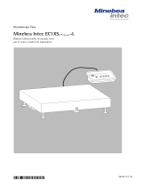
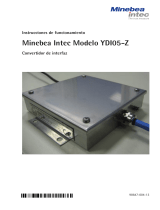
Dimensions
(in mm)
a b c d e
(mm) (mm) (mm) (mm) (mm) Design
320 240 72…90 264 184 ...DC -
400 300 94…109 344 244 ...ED -
500 400 96...111 443 343 ...FE -
650 500 90±2 550 400 ...GF -
800 600 90±2 700 500 ...IG -
800 800 90 604 604 ...II -
1000 800 90 804 604 ...LI -
1000 1000 90 804 804 ...LL -
1250 1000 90 1054 804 ...NL -
1250 1250 90 1054 1054 ...NN -
1500 1250 90 1304 1054 ...RN -
1500 1500 90 1304 1304 ...RR -
2000 1500 100 1804 1304 ...WR -
Design: ..DC, ..ED, ..FE, ..GF, ..IG Design: ..II, ..LI, ..LL, ..NL, ..NN, ..RN, ..RR, ..WR

18 EC1XS... EC1XS... 19
Installing a Column
Product Order No.
Column YBH01CWS
§ Install the column as shown.
Floor-mounted column YDH03CIS
§ Run cables down the back of the column as shown.
§ Affix clips at evenly-spaced intervals.
Base for installing the YDH03CIS floor-mounted column YBP03CIS

18 EC1XS... EC1XS... 19
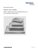
Economy-Ex Full Range Scale
EC1X S 1 – 300 FE – L
Display Finish: Number of Selection of the weighing capacity in kg Resolution:
unit S = Stainless load cells 15,000 d = L
steel
600 150060 150 300
15
6
33000
30
DC
320 + 240
ED
400 + 300
FE
500 + 400
RR
1500 + 1500
RN
1500 + 1250
NN
1250 + 1250
NL
1250 + 1000
LL
1000 + 1000
LI
1000 + 800
II
800 + 800
IG
800 + 600
GF
650 + 500
WR
2000 + 1500
600 150060 150 300
15
6
33000
30
DC
320 + 240
ED
400 + 300
FE
500 + 400
RR
1500 + 1500
RN
1500 + 1250
NN
1250 + 1250
NL
1250 + 1000
LL
1000 + 1000
LI
1000 + 800
II
800 + 800
IG
800 + 600
GF
650 + 500
WR
2000 + 1500
4 Wägezellen
1 Wägezelle
Code for platform
dimensions for EC1XS
C = 240
D = 300|320
E = 400
F = 500
G = 600|650
I = 800
L = 1000
N = 1250
R = 1500
W = 2000
Number of
load cells
4 Wägezellen
1 Wägezelle
EC1X S 4
Example of an order number for EC1XS with 4 load cells: EC1XS4-1500 LL-L
0.2 0.5 1 2 5 10 20 50 100 200
Readability in g

20 EC1XS... EC1XS... 21
Product Order No.
Verifiable strip and label printer with thermal print head, paper width 60 mm,
with adapter cable (12-pin round male connector) and external power supply. YDP04IS-0CE
Printer paper (3 rolls) for YDP04/12IS, 60 mm + 75 mm, thermo paper 69Y03090
– Labels for YDP04/12IS, small, 58 + 30 mm; 1000 labels 69Y03092
– Labels for YDP04/12IS, medium, 58 mm + 76 mm; 500 labels 69Y03093
– Labels for YDP04/12IS, large, 58 + 100 mm; 350 labels 69Y03094
– Adapter cable 69Y03142
Required for direct connection of the YDP04/12IS printer.
For connection over the YDI02-Z.. Zener barrier.
Verifiable printer with functions for date, time and statistical evaluations and LCD. YDP03-0CE
– Printer paper (5 rolls; length per roll: 50 m) 6906937
– Replacement ink ribbon cartridge for printer 6906918
– Adapter cable (3 m, 12-pin round to 9-pin D-SUB) for connecting YCC01-0016M3
a printer over the a Zener barrier to the display and control unit
For use with the data cable supplied: direct connection to the data cable YCC01-0019M3
(3 m, 12-pin round to 9-pin D-SUB)
– Adapter cable (5 m, 12-pin round to 25-contact D-SUB) for connecting YCC01-3ISM5
a computer over a Zener barrier to the display and control unit
Alternatively, (5 m, 12-pin round to 9-pin D-SUB) for connecting a computer YCC01-09ISM5
over a Zener barrier to the display and control unit
– Cable for RS-422 connection to the YDI05-Z YCC422-X
– Cable gland for cable with a d 4.9 mm to 9 mm YAS04CIS
Power supplies/AC adapters:
For installation in the hazardous area YPS05-XD
(see “Certificates” for EX-approvals)
For installation outside the hazardous area YPS05-ZD
(with country-specific power cord and plug, IEC 320/7)
Calibration weights Available on request.
Extensive assortment,
optionally with DKD* certificate
Bracket for wall mounting for the display and control unit YDH01CIS
Bracket for wall mounting (tiltable) for the display and control unit YDH02CIS
Retainer plate for the display and control unit YDH12CWS
Data output: RS-422 YDO05-X
Interface converter, available with various options YDI05-Z
(see service specifications for the YDI05-Z or Drawing 65710-740-50-A4 under “Certificates”)
Options: A24, M51, M55 RS-232 ——- RS-232
Options: A25, M53, M55 (EC1XS equipped with optional YDO05-X data output) RS-422 ——- RS-232 for YDO05-X
Foot switch YPE05-X
* DKD = German Calibration Service, recognized throughout Europe
Accessories
/